CORNING ECL-C4U User manual

009-221, Issue 8
STANDARD RECOMMENDED PROCEDURE 009-221 | ISSUE 8 | AUGUST 2015 | PAGE 1 OF 10
ECL-C4U Connector Housing
related literature | Search www.corning.com/opcomm. Click on “Resources.”
1. General
This instruction describes the installation of the Eclipse® Connector Housing (ECL-C4U) (Figure 1)
manufactured by Corning Optical Communications.
The C4U housing is a rack-mounted ber optic connector housing designed for use in CATV
applications in headend and hub locations. It accepts up to twelve (12) connector panels or
modules. Direct connectorization of loose tube cables can be performed in the unit using the Buffer
Tube Fan-out Kit (ordered separately). Connectorized pigtails may also be used when the C4U
housing is used in conjunction with a splice housing (p/n ECL-S4U).
Figure 1
2. Carton Contents
Figure 2 shows the major components of an ECL-C4U housing. Also included with the housing are
the following:
• Cable ties (12)
• Universal Cable Clamp Kit (1)
• Spiral wrap
• 10-32 rack-mount screws (4)
• 12-24 rack-mount screws (4)
• 6-32 bracket screws (6)
• 19-inch mounting brackets (2)
• 23-inch mounting brackets (2)
• Jumper trough kit (1)
• Buffer tube fan-out bracket (1)
• Hardware kit for securing the cable
strength members
KPA-2187

STANDARD RECOMMENDED PROCEDURE 009-221 | ISSUE 8 | AUGUST 2015 | PAGE 2 OF 10
Figure 2
3. Tools and Materials Required
In addition to the usual complement of tools, you will need 5/16-inch and 3/8-inch nut drivers.
4. Planning
Before you begin your installation, make sure you understand how the unit is to be installed,
where it will be placed in the equipment rack, where the cables will enter the unit, and how the
jumpers will be routed.
If you plan to route pigtails through one or more of the feed-through ports at the rear of the unit
(for example: to splice into splice trays in another unit), remove the plates covering those ports
at this time. Notice that removing the rear door will simplify lower port plate removal. Slide rear
door to the left to remove it.
5. Mounting/Grounding the Housing
5.1 Unstubbed Housing
The housing is equipped to mount into a 19- or 23-inch equipment rack with EIA-310 universal
hole spacing.
KPA-2189
Pass-through port
Connector panels Strain-relief bracket
Strain-relief bracket
mounting holes
Entry grommet
Mounting ear
Jumper routing guides
Fiber retaining clip
Jumper trough
Door stop
Door
latch

STANDARD RECOMMENDED PROCEDURE 009-221 | ISSUE 8 | AUGUST 2015 | PAGE 3 OF 10
Step 1: To install the housing from the front of the equipment rack, attach the appropriate
mounting brackets (Figure 3) to the supporting ange on the housing using the 6-32
screws provided.
Step 2: Remove paint from the mounting bracket with sandpaper at one of the mounting hole
locations to provide metal-to-metal contact for grounding the housing.
Step 3: Mount the housing to the equipment rack using thread-cutting screws.
NOTE: The mounting bracket must have metal-to-metal contact providing an electrical path to properly
ground the housing.
19-inch rack-mount bracket 23-inch rack-mount bracket
Figure 3
5.2 Stubbed Housing
Factory-stubbed units are available with a specic length of preconnectorized cable installed
and strain-relieved in the unit. Install stubbed
housings from the rear of the equipment rack.
Step 1: Slide the housing into the equipment
rack from the rear before attaching
the mounting brackets.
Step 2: While supporting the unit, install the
appropriate mounting brackets using
the 6-32 screws provided as shown in
Figure 3.
Step 3: Fasten the brackets to the equipment
rack using the screws provided. (If
mounting to an Eclipse frame, use the
12-24 screws provided.)
IMPORTANT: Align the top mounting hole of the housing so that the next hole above is 1/2 inch higher
(Figure 4). Doing otherwise will result in the misalignment of the lower mounting holes.
KPA-2190 KPA-2191
KPA-2192
Figure 4

STANDARD RECOMMENDED PROCEDURE 009-221 | ISSUE 8 | AUGUST 2015 | PAGE 4 OF 10
6. Install Connector Panels or Modules
The ECL-C4U housing will accommodate up to
twelve connector panels or modules. They are
secured to the front of the housing with plastic
push-pull plunger fasteners. Secure the panels or
modules to the housing as shown in Figure 5.
7. Install Cable
7.1 Removing Doors
The front and rear doors may be removed to ease
installation. To remove rear door, slide it to the left
to release the hinges. To remove the front door,
lift the lever arm on the left side of the trough and
slide the door to the left (Figure 6). Reverse these
procedures to replace the doors.
7.2 Preparing Cable
WARNING: Never look directly into the end of a ber that may be carrying laser light.
Laser light can be invisible and can damage your eyes. Viewing it directly does not cause pain.
The iris of the eye will not close involuntarily as when viewing a bright light. Consequently,
serious damage to the retina of the eye is possible. Should accidental eye exposure to laser
light be suspected, arrange for an eye examination immediately.
WARNING: DO NOT use magniers in the presence of laser radiation. Diffused laser light
can cause eye damage if focused with optical instruments. Should accidental eye exposure to
laser light be suspected, arrange for an eye examination immediately.
CAUTION: Cleaved or broken glass bers are very sharp and can pierce the skin easily. Do
not let these pieces of ber stick to your clothing or drop in the work area where they can
cause injury later. Use tweezers to pick up cleaved or broken pieces of glass bers and place
them on a loop of tape kept for that purpose alone. Good housekeeping is very important.
Plunger
Plunger
Housing
Expanded
Fingers
KPA-2193
• Pull both plungers out
all the way.
• Position the two nylon
fasteners into the
mounting holes
• Press the plungers on
the fasteners.
To remove, pull the
plunger out.
Figure 5
Door Stop
KPA-2194
Figure 6

STANDARD RECOMMENDED PROCEDURE 009-221 | ISSUE 8 | AUGUST 2015 | PAGE 5 OF 10
CAUTION: Corning recommends the use of safety glasses (spectacles) conforming to ANSI
Z87 for eye protection from accidental injury when handling chemicals, cables, or working with
ber. Pieces of glass ber are very sharp and have the potential to damage the eye.
CAUTION: Fiber optic cable is sensitive to excessive pulling, bending, and crushing forces.
Consult the cable specication sheet for the cable you are installing. Do not bend the cable
more sharply than the minimum recommended bend radius. Do not apply more pulling force
to the cable than specied. Do not crush the cable or allow it to kink. Doing so may cause
damage that can alter the transmission characteristics of the cable; the cable may have to be
replaced.
Fiber optic cable is generally routed to the
housing, strain-relieved on the side, and routed
to the back of connector panels inside the
housing.
Step 1: Determine the opening where the
cable will enter the housing.
Step 2: Puncture the grommet or peel away
the center section of the grommet,
leaving an edge grommet (Figure 7).
Step 3: Prepare the cable as outlined in
sheath removal instructions for the
cable you are installing. See Figure
8 for suggested component lengths. If you plan to use the Universal Cable Clamp
(UCC) kit for strain-relief, remove the central member and yarn, if present.
Figure 8
KPA-2195
Entry
grommet
Figure 7
Fiber for buffer tube fan-out
installation (see connector
instructions) Central member
10 cm (4 in)
Buffer tubes
76 cm (30 in) Yarn
10 cm (4 in)
Loose-Tube Cable
Tight-Buffered Cable
10 cm
(4 in)
200 cm
(79 in)
10 cm
(4 in)
16 cm
(10 in)
KPA-2196

STANDARD RECOMMENDED PROCEDURE 009-221 | ISSUE 8 | AUGUST 2015 | PAGE 6 OF 10
7.2.1 Strain-relieving Cable in a Controlled Environment
If the last 10 m (33 ft) of the cable you are terminating is
located in a controlled environment where temperatures
uctuate very little, it is not necessary to secure the cable
strength members (yarn and/or central member). The cable
can be strain-relieved by using the UCC (Figure 9).
When using the UCC, the clampshell must be attached to
the strain-relief bracket before the bracket is attached to the
housing (Figure 9). Refer to the instructions supplied with
the UCC kit.
7.2.2 Strain-relieving Cable in an
Uncontrolled Environment
If terminating a cable where temperatures uctuate widely
along the last 10m (33 ft) of the cable, the strength members
must be secured (see Figures 10 and 11). Failing to do so
may result in damage to the cable as temperatures vary.
On the Outside of the Housing
Figure 10
KPA-2197
Figure 9
KPA-2198
Attach the cable to the strain-relief
bracket with cable ties and components
in the strain-relief kit. To attach the
bracket to the outside of the unit,
insert the studs into the mounting holes
on the side of the housing. Make sure
to select the correct mounting holes to
ensure proper bend radius upon entering
the unit. Use the wing nuts provided in the
kit to fasten the bracket to the housing.
Both the aramid or fiberglass yarn and
the central member are secured with a
U-shaped washer and bolt. Insert the
metallic central member between the
U-shaped washer and the M6 flat washer.
Wrap yarn between the U-shaped washer
and the side of the bracket. Tighten the nut.

STANDARD RECOMMENDED PROCEDURE 009-221 | ISSUE 8 | AUGUST 2015 | PAGE 7 OF 10
Inside the Housing
Figure 11
7.3 Installing Loose Tube Cable
Step 1: Prepare loose tube cable for
installation of Buffer Tube Fan-out
(BTF) kits (purchased separately).
Step 2: Follow the directions provided with
the BTF kit to install the fan-out
bodies.
Step 3: Secure the fan-out bodies to the
bracket with a cable tie (Figure 12).
Step 4: Attach the bracket in the rear of the
housing at the top using 6-32 screws
(Figure 13).
Figure 13
KPA-2188
Cable Tie
KPA-2199
Figure 12
Attachment point for
buffer tube fan-out bracket
KPA-2201

STANDARD RECOMMENDED PROCEDURE 009-221 | ISSUE 8 | AUGUST 2015 | PAGE 8 OF 10
7.3.1 Routing Cable
Step 1: Install connectors on the bers per instructions provided with the connectors.
Step 2: Route the ber slack inside the housing in the pattern shown in Figure 13.
Step 3: Clean the adapters and connector end-faces per standard company practices or as
described in Section 9; then plug the connectors into the adapters at the rear of the
connector panels.
Step 4: If routing pigtails to the housing, attach an identication tag to the end of each
bundle, indicating the number of the panel to which it is attached. Pigtail bers can
be routed through the pass-through ports in the top and bottom of the housing to
splice hardware in splice shelves.
Step 5: Attach a numerical identication tag to each tight-buffered ber, indicating the
connector location on the panel.
NOTE: If it is necessary to remove any excess length of spiral-wrapped ber, make sure to place new
identication tags on the new working length prior to removing the excess.
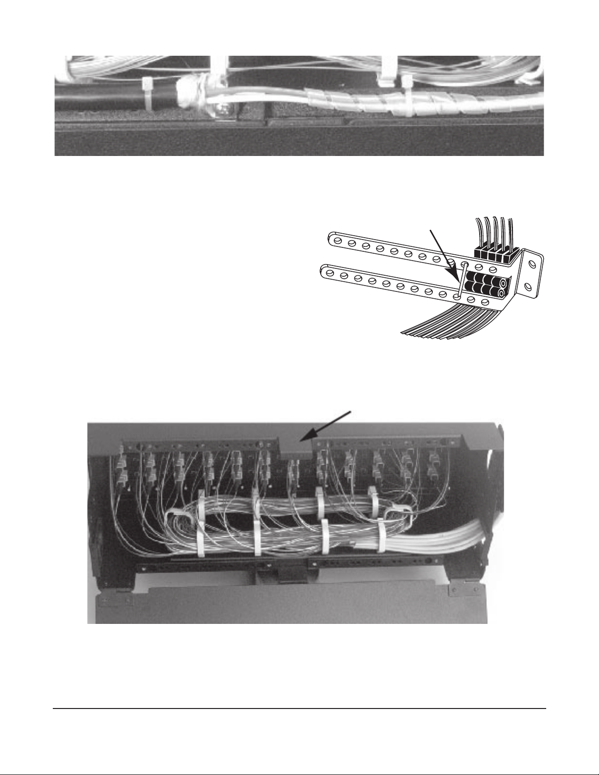
7.3.2 Install Jumpers
In the CATV environment where moves,
adds, and changes are frequent, good
jumper management and record keeping
are imperative. To help maintain a neat and
organized installation, Corning strongly
recommends the use of the Jumper
Management Panel and the Inter-Bay Storage
Unit (Figure 14) (contact your Corning
Optical Communications customer care
representative for assistance).
If using the jumper management panel, route
jumpers through the management panel and down into the C4U housing (Figure 14). Otherwise,
route jumpers into the housing from either side over the jumper trough (Figure 15), or in through
the ports in the oor of the housing (Figure 16).
NOTE: Allow the minimum bend radius when inserting the jumpers into the routing clip and routing the
jumpers out of the housing. Do not apply more pulling force to the cable than specied. Do not
use the clip when routing to a jumper management panel above the C4U housing.
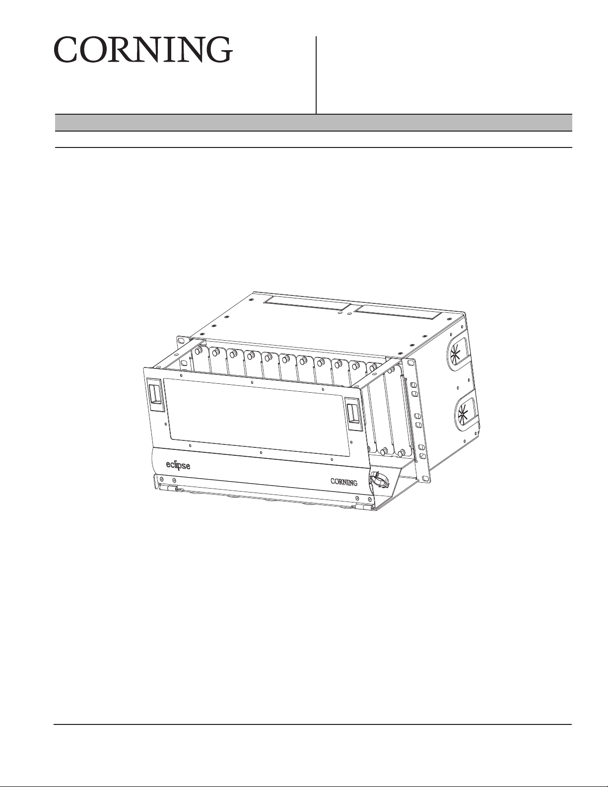
7.3.3 Jumper Management Using
Jumper Trough
Step 1: Install jumper trough in the front of the housing
using the two screws provided (Figure 15).
Step 2: Route jumpers through the routing clip
below the applicable adapter panel. Or route
jumpers through the jumper management
panel as shown in Figure 14.
Step 3: Clean the adapters and connector end-faces.
Mate the connectors in the adapters.
KPA-2204
Figure 14
KPA-2202
Figure 15

STANDARD RECOMMENDED PROCEDURE 009-221 | ISSUE 8 | AUGUST 2015 | PAGE 9 OF 10
Step 4: Record an identier for each connection on the ip cards located on the front door,
either by writing directly on the card or by using computer printed labels.
7.3.4 Jumper Management Without
Jumper Trough
Step 1: Route jumpers through the port openings
in the oor of the housing and through the
routing clip below the applicable adapter
panel (Figure 16). Or route jumpers
through the jumper management panel
into the C4U housing as shown in
Figure 14.
Step 2: Clean the adapters and connector
end-faces. Mate the connectors in the
adapters.
Figure 16
Step 3: Record an identier for each connection on the ip cards located on the front door,
either by writing directly on the card or by using computer printed labels.
8. Connector Care and Cleaning
WARNING: Isopropyl alcohol is ammable with a ashpoint at 54ºF. It can cause irritation to
eyes on contact. In case of contact, ush eyes with water for at least 15 minutes. Inhalation
of vapors irritates the respiratory tract. Exposure to high concentrations has a narcotic effect,
producing symptoms of dizziness, drowsiness, headache, staggering, unconsciousness and
possibly death.
• Always keep dust caps on connectors and adapters when not in use.
• Ensure dust caps are clean before reuse.
• Use optical cleaning materials as standardized by your company.
• Clean the connector before every mating, especially for test equipment patch cords
(jumpers).
• A minimum level of cleaning is listed below. Local procedures may require more rigorous
cleaning methods.
Step 1: Remove plugs from the connector adapter.
Step 2: Wipe the connector ferrule twice with a lint-free wiping material moistened with
isopropyl alcohol. Then wipe across the end of the ferrule.
Step 3: Repeat previous step with a dry wipe.
KPA-2203
Waterfall
Removed

STANDARD RECOMMENDED PROCEDURE 009-221 | ISSUE 8 | AUGUST 2015 | PAGE 10 OF 10
Corning Optical Communications LLC • PO Box 489 • Hickory, NC 28603-0489 USA
800-743-2675 • FAX: 828-325-5060 • International: +1-828-901-5000 • www.corning.com/opcomm
Corning Optical Communications reserves the right to improve, enhance, and modify the features and specications of Corning Optical Communications products
without prior notication. A complete listing of the trademarks of Corning Optical Communications is available at www.corning.com/opcomm/trademarks. All other
trademarks are the properties of their respective owners. Corning Optical Communications is ISO 9001 certied. © 1997-2000, 2003, 2009, 2015 Corning Optical
Communications. All rights reserved.
9. Maintenance
The unit requires very little maintenance to ensure bers and parts remain in good condition.
• External components may be cleaned occasionally with a damp, nonabrasive cloth.
• Check nuts, bolts, and screws; tighten as needed.
• Check ber optic cable to make sure bends do not exceed the minimum bend radius.
• Check cables for unnecessary strain, for crimping or crushing at entries and exits, and for
damage.
• Check unit record labels to make sure all are clear and accurate.
10. Dimensions
Figure 17
44 cm
(17 in)
17.8 cm
(7 in)
21.3 cm
(8 in)
51.6 cm
(20 in)
12.4 cm
(5 in)
KPA-2205
Table of contents
Other CORNING Cables And Connectors manuals

CORNING
CORNING EDGE Splice Cassette User manual

CORNING
CORNING EDGE-01U-SP User manual

CORNING
CORNING Evolant TKT-OPTISNAP-Cx User manual

CORNING
CORNING SRP-004-067 User manual

CORNING
CORNING X75 8000 Series User manual

CORNING
CORNING UCNCP 5 MFT Flip HS Series User manual

CORNING
CORNING PCH-02U User manual

CORNING
CORNING UniCam SRP-006-150 User manual

CORNING
CORNING SST-Drop User manual

CORNING
CORNING UCNCP 5 MFT Flip HS Series User manual