stud welding products StudPro 2500i User manual

OPERATION MANUAL
MODELS
TWE-250
TWE-321
TWE-375
TRU‐WELDEQUIPMENTCOMPANY
6400N.HONEYTOWNROAD
SMITHVILLE,OHIO44677
(330)669‐2773
Downey, CA
9459 Washburn Rd.
Downey, CA 90242
Phone- 800.252.1919
Fax- 562.862.3022
Hayward, CA
2391 American Ave.
Hayward, CA 94545
Phone- 510.782.7883
Fax- 510.782.7918
Renton, WA
927 Thomas Ave. SW
Renton, WA 98057
Phone- 425.656.9787
Fax- 425.656.9786
Phoenix, AZ
3535 East Wier Ave., Ste. #4
Phoenix, AZ 85040
Phone- 602.305.9350
Fax- 602.305.4890
Toll free customer support: 1.800.252.1919
MODEL
StudPro 2500i

2
22
CONTENTS
SectionDescriptionPages
1Introduction3
2ExternalFeatures4‐5
3Safety6‐8
4SetupandWelding9‐15
5TestingWeldSettings16
6InspectingTheWeld17
7CDStudGunViews18
8CDStudGunExplodedView19
9CDStudGunPartsList20
10CDControllerExplodedView21
11CDControllerPartsList22
1 Introducon 3
2 External Features 4-5
3 Safety 6-8
4 SetupandWelding 9-15
5 TesngWeldSengs 16-19
6 TypesofFractures 20
7 ArcBlowEect 21
8 CDStudGunExplodedView 22
9 InternalComponents 23-25
10 CDAccessoreis 26-30
11 TorqueBendingTest 31-32
12 CDGunSetUp’s 33-34
1 Introducon 3
2 External Features 4-5
3 Safety 6-8
4 SetupandWelding 9-15
5 CupHeadWelding 16-17
6 TesngWeldSengs 18-21
7 TypesofFractures 22
8 ArcBlowEect 23
9 CDStudGunExplodedView 24
10 InternalComponents 25-27
11 CDAccessoreis 28-32
12 TorqueBendingTest 33-34
13 CDGunSetUp’s 35-36

3
33
Thecompleterangeofthecapacitordischargeequipmentiscompact,portablestud
weldingequipment.Theunitsarespecificallydesignedtoenableasmalldiameter
rangeofferrousandnonferrousweldstudstobeweldedtolightgaugemetalmateri‐
alswithlittleornoreverse‐sidemarking.
Theequipmentconsistsofacontrolunit,aweldinghandgun,andallnecessaryinter‐
connectingcables.
THEPROCESS
CapacitorDischarge(CD)studweldingisaformofweldinginwhichtheenergyre‐
quiredfortheweldingprocessisderivedfromabankofchargedcapacitors.This
storedenergyisdischargedatthebaseofthespeciallydesignedCDstudanditfuses
thestudtothebasematerial.Thetimeoftheweldisdeterminedinsuchashortdu‐
rationthatnoburnthroughmarkingismadeonthefinishsideofthematerial.
CONTACT
IncontactCDwelding,thestudisplacedunderspringpressureonthematerialtobe
welded.Whenthecapacitorsaredischarged,thespecialtipoftheCDstudmeltsand
thespringpressureforcesthestudtofusewiththebasematerial.
GAP
IngapCDwelding,thestudisplacedontothematerialtobewelded.Asthestudgun
isengaged,thestudliftsfromthebasematerialandthenreturnstothepointofcon‐
tactatthetimeofthedischargeofthecapacitors.Asthecapacitorsdischarge,melt‐
ingthetipoftheweldstud,thepressurecreatedbythemovementofthestudtothe
basematerialbythestudgunfusesthestudtothebasematerial.
INTRODUCTION

4
4
4
FRONTPANEL
1.WeldVoltageSelector‐rotatetochangetorequiredvoltage.
2.WeldingVoltageDigitalDisplay‐displaysselectedvoltage.
3.LEDLights‐Charging(capacitorsarebeingchargingtodesiredvoltage),Ready
(unitisreadytoweld),Reset(indicatesanerrorandunitshouldbeturnedoff).
4.WeldingGroundCableConnector(+)
5.StudGunControlConnector
6.WeldingStudGunCableConnector(‐)
EXTERNAL FEATURES
1
4
2
56
3
1
2
3
654
7. GroundCupHead
7

5
55
REARPANEL
1.On/OffSwitch
2.FuseHolder(10amp)
3.ACPowerCord
4.ManufacturerModelNumberandSerialNumberPlate
WARNING!
Thisunitoperatesfroma110VAC60Hertz@10ampcircuit.
Donotobstructtheventilationfan,asthismaycauseunittooverheat.
Donotremoveanyportionoftheunithousingwithoutfirstdisconnectingtheunit
fromthepowersupply.
EXTERNAL FEATURES
ON/OFFSwitch
15AmpFuse
PowerSupplyFan
ACCord
ON/OFF Switch
15Amp Fuse
Power Supply Fan
AC Cord

6
6
6
PROTECTYOURSELFANDOTHERS!
Readthesafetynoticesbeforeusingwelder.
ELECTRICAL
Noportionoftheoutercoveroftheweldingcontrollershouldberemovedbyany‐
oneotherthanqualifiedpersonnel.Alwaysdisconnecttheunitfromthemainpower
priortoremovingcover.
• Thisequipmentcontainsatransformerpowersupplysystem,whichisenergized
byACcurrentandtransformstheACtoDCcurrent.Duetopotentialdangerous
electricalinputandoutputtheequipmentmustbedisconnectedfromallincom‐
ingpowerwhenservicing.
• Capacitorsstoreelectricalenergy.Checkforresidualchargebeforeperforming
anymaintenance.
• Donotusefluidstocleanelectricalcomponentsasthesemaypenetratetheelec‐
tricalsystemandcauseshorts.
Connectionoftheunitintoservicemustbeinaccordancewiththesetupprocedures
asdetailedinthismanual.Operationofthisequipmentmustbeinaccordancewith
alllocal,regional,andnationalsafetycodes.
SAFETY

7
77
FIRE
Duringwelding,smallparticlesofhotmetalcanbeexpelled.Ensurethatnocombus‐
tiblematerialsareneartheweldingarea.
PERSONALSAFETY
Arcrayscanburnyoureyesandskin.Wearprotectiveclothingandeyeprotection
whenwelding.
Loudnoisesfromweldingcandamagehearing.Wearearplugsorotherprotective
gear,ifapplicable.
Fumesandgasesexpelledduringweldingcanbehazardoustoyourhealth.Make
sureweldingisdoneinawell‐ventilatedarea.
Hotmetalsplattercancausefiresandburns.Wearprotectiveclothing,freeofcom‐
bustiblematerials.Haveafireextinguishernearbyandknowhowtouseit.
MAINTENANCE
Allcablesmustbeinspectedregularlytoensurethatnodangerexistsfromwornor
damagedinsulationorunsafeelectricalconnections.Takespecialnotetothecables
nearthestudgun‐thisiswheremaximumwearoccurs.
Worncablesnotonlyproduceinconsistentwelds,butcanoverheatorspark.
SAFETY
FIRE HAZARD
FROM SPARKS

8
8
8
TRAINING
Useofthisequipmentmustbelimitedtoauthorizedpersonnelonly.Theymustbe
adequatelytrained,andhavereadandunderstoodeverythinginthismanual.The
manualmustbeavailabletooperatorsatalltimes.
INSTALLATION
Selectasitefortheequipmentwhichiscapableofsupportingtheweightofthe
equipment,whichisclearfromtrafficrouteswherepeoplemaytripovercables,or
theymaybedamagedbyotherequipmentorvehicles.
Donothangconnectingcablesoversharpedgesorhavenearheatsources.
DISPOSAL
Theequipment,initsentiretyorascomponents/partsmaybedisposedofasgeneral
industrialwasteorscrap.Noneofthecomponentsusedinthemanufacturingofthe
CDWeldersaretoxic,carcinogenic,orotherwiseharmfultoyourhealth.
SAFETY
AUTHORIZED
PERSONNEL ONLY

9
99
POWERINGUPTHEEQUIPMENT
Setuptheequipmentpowersupply(ControlUnit)andconnecttothemainpower,
makingcertainofthepropervoltagerequirementoftheparticularunit.
CapacitorDischarge(CD)unitsgenerallyrequire110VAC@60Hzincomingpower.
Refertothesafetyrecommendationsbeforepluggingthisunitin.
ON/OFFSwitch
Fuse
PowerCord(110VAC)
CONNECTINGTHEWELDINGLEADS
Connecttheweldinggroundcableintothe(+)terminalmountsocketonthefrontof
theweldingunit.
***NOTE‐thecableendplughasaflatwhichalignswithadotonthepanelmount
socket.Securetheconnectorintothepanelmountsocket,andthenturnitclockwise
untilitlocksintoproperposition.Failuretodosocouldresultindamagetothecon‐
nector.
GroundCableSocket
SET-UP AND WELDING
ON/OFF Switch
Fuse
Power Cord (110 VAC)
For Cup Head to
Ground Cable Socket

10
10
10
CONNECTINGTHEWELDINGLEADS
Connecttheweldingstudgunpowercableintothe(‐)terminalpanelmountsocket
(designatedbythegunsymbol)onthefrontoftheweldingunit.
***NOTE‐thecableendplughasaflatwhichalignswithadotonthepanelmount
socket.Securetheconnectorintothepanelmountsocket,andthenturnitclockwise
untilitlocksintoproperposition.Failuretodosocouldresultindamagetothecon‐
nector.
WeldingGunPowerConnector
WeldingGunControlCableConnector
Connecttheweldguncontrolcableintothecenterpanel2‐pinsocket.
**NOTE‐theplughasalargepinandasmallpinthatmatchthesocketontheunit.
Thisistopreventincorrectconnections.Pushtheplugfirmlyintothesocketand
twistclockwisetosecuretheplugintothecorrectposition.
SET-UP AND WELDING
Welding Gun Control Cable Connector
Welding Gun Power Connector

11
1111
CONNECTINGTHEGROUNDCLAMP
Attachtheclampoftheweldinggroundleadtotheworkpiece.Priortosecuringthe
clamp,makecertainthatthecontactareaisfreeofrust,paint,grease,oranyother
impuritiestoensureagoodgroundconnection.
NOTE***Mostapplicationswillrequireonlyonegroundclamp,butcertainapplica‐
tionswillrequireanadditionaldualclamp.
SET-UP AND WELDING
13
CONNECTINGTHEGROUNDCLAMP
Attachtheclampoftheweldinggroundleadtotheworkpiece.Priortosecuringthe
clamp,makecertainthatthecontactareaisfreeofrust,paint,grease,oranyother
impuritiestoensureagoodgroundconnection.
NOTE***Mostapplicationswillrequireonlyonegroundclamp,butcertainapplica‐
tionswillrequireanadditionaldualclamp.
SET-UP AND WELDING
12
12
14
SELECTINGTHEPROPERSTUDCOLLET(STUDHOLDER)
Thecolletisselectedtotheproperdiameterthatyouarewelding.
Therearethreestylesofcollets;
• The“B”colletwhichisatwo‐pieceassembly(colletandinsert).Theinsertdeter‐
mineshowmuchofthestudisengagedinthecollet.
• TheCI(ColletInsert)whichisasinglepartandtheamountofthestudthatisen‐
gagedispredetermined.
• EuroColletshaveanadjustableinternalscrewtomanuallyadjust
fortheengagementofthestud.
Thechoicebetweenthesesystemsisusuallyamatterofpersonalpreference.
Insertingtheselectedcolletintothestudgunisasimpletask.Placethecolletinto
thefrontholderofthestudgunandsetthelockingscrewstoholditinplace.
Afterinsertingthecollet,mountthetwolegsandfootpieceontothestudgun.The
colletshouldbecenteredthroughtheopeningofthefootpiece.
Whenthelegsandfootpieceareinplace,insertthestudtobeweldedintothecol‐
let.Adjustthelegandfootpiecebyslidingitintopositionuntilapproximately1/8”
ofthestudprotrudesfrombeyondthefootpiece.Locklegsinplacewiththeset
screws.
SET-UP AND WELDING
FootPiece
Collet
LegPiece
12
SELECTINGTHEPROPERSTUDCOLLET(STUDHOLDER)
Thecolletisselectedtotheproperdiameterthatyouarewelding.
Therearethreestylesofcollets;
• The“B”colletwhichisatwo‐pieceassembly(colletandinsert).Theinsertdeter‐
mineshowmuchofthestudisengagedinthecollet.
• TheCI(ColletInsert)whichisasinglepartandtheamountofthestudthatisen‐
gagedispredetermined.
• StandardAdjustableChuckshaveanadjustableinternalscrewtomanuallyadjust
fortheengagementofthestud.
Thechoicebetweenthesesystemsisusuallyamatterofpersonalpreference.
Insertingtheselectedcolletintothestudgunisasimpletask.Placethecolletinto
thefrontholderofthestudgunandsetthelockingscrewstoholditinplace.
Afterinsertingthecollet,mountthetwolegsandfootpieceontothestudgun.The
colletshouldbecenteredthroughtheopeningofthefootpiece.
Whenthelegsandfootpieceareinplace,insertthestudtobeweldedintothecol‐
let.Adjustthelegandfootpiecebyslidingitintopositionuntilapproximately1/8”
ofthestudprotrudesfrombeyondthefootpiece.Locklegsinplacewiththeset
screws.
SET-UP AND WELDING
FootPiece
Collet
LegPiece
Adapterisrequired.
Adapterisrequired.
Nofootpieceorlegsrequiredwhenweldingcupheadpins.
Forcupheadpinsusecupheadpincollet
Thechoicebetweenthesesystemsisusuallyamaerofpersonalpreference.
12
14
SELECTINGTHEPROPERSTUDCOLLET(STUDHOLDER)
Thecolletisselectedtotheproperdiameterthatyouarewelding.
Therearethreestylesofcollets;
• The“B”colletwhichisatwo‐pieceassembly(colletandinsert).Theinsertdeter‐
mineshowmuchofthestudisengagedinthecollet.
• TheCI(ColletInsert)whichisasinglepartandtheamountofthestudthatisen‐
gagedispredetermined.
• EuroColletshaveanadjustableinternalscrewtomanuallyadjust
fortheengagementofthestud.
Thechoicebetweenthesesystemsisusuallyamatterofpersonalpreference.
Insertingtheselectedcolletintothestudgunisasimpletask.Placethecolletinto
thefrontholderofthestudgunandsetthelockingscrewstoholditinplace.
Afterinsertingthecollet,mountthetwolegsandfootpieceontothestudgun.The
colletshouldbecenteredthroughtheopeningofthefootpiece.
Whenthelegsandfootpieceareinplace,insertthestudtobeweldedintothecol‐
let.Adjustthelegandfootpiecebyslidingitintopositionuntilapproximately1/8”
ofthestudprotrudesfrombeyondthefootpiece.Locklegsinplacewiththeset
screws.
SET-UP AND WELDING
FootPiece
Collet
LegPiece
12
SELECTINGTHEPROPERSTUDCOLLET(STUDHOLDER)
Thecolletisselectedtotheproperdiameterthatyouarewelding.
Therearethreestylesofcollets;
• The“B”colletwhichisatwo‐pieceassembly(colletandinsert).Theinsertdeter‐
mineshowmuchofthestudisengagedinthecollet.
• TheCI(ColletInsert)whichisasinglepartandtheamountofthestudthatisen‐
gagedispredetermined.
• StandardAdjustableChuckshaveanadjustableinternalscrewtomanuallyadjust
fortheengagementofthestud.
Thechoicebetweenthesesystemsisusuallyamatterofpersonalpreference.
Insertingtheselectedcolletintothestudgunisasimpletask.Placethecolletinto
thefrontholderofthestudgunandsetthelockingscrewstoholditinplace.
Afterinsertingthecollet,mountthetwolegsandfootpieceontothestudgun.The
colletshouldbecenteredthroughtheopeningofthefootpiece.
Whenthelegsandfootpieceareinplace,insertthestudtobeweldedintothecol‐
let.Adjustthelegandfootpiecebyslidingitintopositionuntilapproximately1/8”
ofthestudprotrudesfrombeyondthefootpiece.Locklegsinplacewiththeset
screws.
SET-UP AND WELDING
FootPiece
Collet
LegPiece
12
14
SELECTINGTHEPROPERSTUDCOLLET(STUDHOLDER)
Thecolletisselectedtotheproperdiameterthatyouarewelding.
Therearethreestylesofcollets;
• The“B”colletwhichisatwo‐pieceassembly(colletandinsert).Theinsertdeter‐
mineshowmuchofthestudisengagedinthecollet.
• TheCI(ColletInsert)whichisasinglepartandtheamountofthestudthatisen‐
gagedispredetermined.
• EuroColletshaveanadjustableinternalscrewtomanuallyadjust
fortheengagementofthestud.
Thechoicebetweenthesesystemsisusuallyamatterofpersonalpreference.
Insertingtheselectedcolletintothestudgunisasimpletask.Placethecolletinto
thefrontholderofthestudgunandsetthelockingscrewstoholditinplace.
Afterinsertingthecollet,mountthetwolegsandfootpieceontothestudgun.The
colletshouldbecenteredthroughtheopeningofthefootpiece.
Whenthelegsandfootpieceareinplace,insertthestudtobeweldedintothecol‐
let.Adjustthelegandfootpiecebyslidingitintopositionuntilapproximately1/8”
ofthestudprotrudesfrombeyondthefootpiece.Locklegsinplacewiththeset
screws.
SET-UP AND WELDING
FootPiece
Collet
LegPiece
12
SELECTINGTHEPROPERSTUDCOLLET(STUDHOLDER)
Thecolletisselectedtotheproperdiameterthatyouarewelding.
Therearethreestylesofcollets;
• The“B”colletwhichisatwo‐pieceassembly(colletandinsert).Theinsertdeter‐
mineshowmuchofthestudisengagedinthecollet.
• TheCI(ColletInsert)whichisasinglepartandtheamountofthestudthatisen‐
gagedispredetermined.
• StandardAdjustableChuckshaveanadjustableinternalscrewtomanuallyadjust
fortheengagementofthestud.
Thechoicebetweenthesesystemsisusuallyamatterofpersonalpreference.
Insertingtheselectedcolletintothestudgunisasimpletask.Placethecolletinto
thefrontholderofthestudgunandsetthelockingscrewstoholditinplace.
Afterinsertingthecollet,mountthetwolegsandfootpieceontothestudgun.The
colletshouldbecenteredthroughtheopeningofthefootpiece.
Whenthelegsandfootpieceareinplace,insertthestudtobeweldedintothecol‐
let.Adjustthelegandfootpiecebyslidingitintopositionuntilapproximately1/8”
ofthestudprotrudesfrombeyondthefootpiece.Locklegsinplacewiththeset
screws.
SET-UP AND WELDING
FootPiece
Collet
LegPiece
MagnecChuck
CupheadPins

13
13
13
SELECTINGTHESPRINGLOAD
Theproperspringpre‐loadsettingonthestudgunwillvarydependingonthese‐
lectedapplication.Generalsrulesofapplicationwouldbe;mildsteelorstainless
steelusuallyinthe1to2range,dependingonthestuddiameterandthethicknessof
thebasematerial.Aluminumandothernonferrousmetalswouldrequiresettings
from3to5dependingonthediameterofthestudandbasematerialthickness.
Thisspringpre‐loadadjustmentismadebyturningthescrewinsertinthebackofthe
studgunwithascrewdriver.Onthebottomofthebackcapofthestudgunisthe
indicatornumbered1thru5,whichwillshowyouthetensionsettingduringthead‐
justment.
SET-UP AND WELDING
AdjustmentScrew
TensionIndicator
15
SELECTINGTHESPRINGLOAD
Theproperspringpre‐loadsettingonthestudgunwillvarydependingonthese‐
lectedapplication.Generalsrulesofapplicationwouldbe;mildsteelorstainless
steelusuallyinthe1to2range,dependingonthestuddiameterandthethicknessof
thebasematerial.Aluminumandothernonferrousmetalswouldrequiresettings
from3to5dependingonthediameterofthestudandbasematerialthickness.
Thisspringpre‐loadadjustmentismadebyturningthebackcapofthestudgun.On
thesideofthestudgunistheindicatornumbered1thru5,whichwillshowyouthe
tensionsettingduringtheadjustment.
SET-UP AND WELDING
AdjustmentCap
TensionIndicator
Locationofadjustment
onbackofthegun.

14
1414
READYFORWELDING
Whenyouhavecompletedallofthepreviousstepstoprepareforwelding,including
connectingthestudgunandgroundcablestotheunit,attachingthegroundcable(s)
totheworkarea,settingupandadjustingthestudgunfortheselectedstuddiame‐
terandmaterial,youcannowpoweronthewelder.
ThecontrollerON/OFFswitchislocatedontherearoftheunitintheupperright
handcorner.Belowthisswitchisthe15ampfuseholderforthesystem.
SET-UP AND WELDING
ON/OFFSWITCH
FUSE
ON/OFF Switch
FUSE

15
1515
VOLTAGESELECTION
Selectingtherequiredweldvoltageisachievedbyturningtheselectorknob.The
voltagerangeisfrom35VDCto200VDC.
Thevoltageisdeterminedbythediameterofthestudandthebasematerial.
Approximatevoltagestaringpointsarelistedbelow.Finetuningthevoltagetomeet
yourrequirementforyourspecificapplicationisrecommended.
NOTE***whenweldingcupped‐headinsulationpins,settheDCVoltageto35voltsto
beginandincreaseasnecessary.AdjustthespringpressureontheCDgunbetween
#1and#3asnecessary.
SET-UP AND WELDING
DiameterVoltage(DC)
14ga.50‐75
12ga.75‐110
#8110‐130
#10125‐160
1/4”160‐190
DiameterVoltage(DC)
14ga.35‐50
12ga.50‐75
#875‐100
#10100‐120
1/4”120‐140
MODELTWE‐321&375
3/8”(TWE‐375)160‐200
5/16”140‐160
VoltageAdjustmentKnob
MODEL 3125 & 3750
(3750)
Voltage Adjustment Knob
MODEL STUDPRO 2500i
1515
VOLTAGESELECTION
Selectingtherequiredweldvoltageisachievedbyturningtheselectorknob.The
voltagerangeisfrom35VDCto200VDC.
Thevoltageisdeterminedbythediameterofthestudandthebasematerial.
Approximatevoltagestaringpointsarelistedbelow.Finetuningthevoltagetomeet
yourrequirementforyourspecificapplicationisrecommended.
NOTE***whenweldingcupped‐headinsulationpins,settheDCVoltageto35voltsto
beginandincreaseasnecessary.AdjustthespringpressureontheCDgunbetween
#1and#3asnecessary.
SET-UP AND WELDING
DiameterVoltage(DC)
14ga.50‐75
12ga.75‐110
#8110‐130
#10125‐160
1/4”160‐190
DiameterVoltage(DC)
14ga.35‐50
12ga.50‐75
#875‐100
#10100‐120
1/4”120‐140
MODELTWE‐321&375
3/8”(TWE‐375)160‐200
5/16”140‐160
VoltageAdjustmentKnob
VOLTAGESELECTION
Selectingtherequiredweldvoltageisachievedbyturningtheselectorknob.The
voltagerangeisfrom35VDCto200VDC.
Thevoltageisdeterminedbythediameterofthestudandthebasematerial.
Approximatevoltagestaringpointsarelistedbelow.Finetuningthevoltagetomeet
yourrequirementforyourspecificapplicationisrecommended.
NOTE***whenweldingcupped‐headinsulationpins,settheDCVoltageto35voltsto
beginandincreaseasnecessary.AdjustthespringpressureontheCDgunbetween
#1and#3asnecessary.
SET-UP AND WELDING
DiameterVoltage(DC)
14ga.50‐75
12ga.75‐110
#8110‐130
#10125‐160
1/4”160‐190
DiameterVoltage(DC)
14ga.35‐50
12ga.50‐75
#875‐100
#10100‐120
1/4”120‐140
MODELTWE‐321&375
3/8”(TWE‐375)160‐200
5/16”140‐160
VoltageAdjustmentKnob
MODEL 3125 & 3750
(3750)
Voltage Adjustment Knob
CupheadPin 70-100
1515
VOLTAGESELECTION
Selectingtherequiredweldvoltageisachievedbyturningtheselectorknob.The
voltagerangeisfrom35VDCto200VDC.
Thevoltageisdeterminedbythediameterofthestudandthebasematerial.
Approximatevoltagestaringpointsarelistedbelow.Finetuningthevoltagetomeet
yourrequirementforyourspecificapplicationisrecommended.
NOTE***whenweldingcupped‐headinsulationpins,settheDCVoltageto35voltsto
beginandincreaseasnecessary.AdjustthespringpressureontheCDgunbetween
#1and#3asnecessary.
SET-UP AND WELDING
DiameterVoltage(DC)
14ga.50‐75
12ga.75‐110
#8110‐130
#10125‐160
1/4”160‐190
DiameterVoltage(DC)
14ga.35‐50
12ga.50‐75
#875‐100
#10100‐120
1/4”120‐140
MODELTWE‐321&375
3/8”(TWE‐375)160‐200
5/16”140‐160
VoltageAdjustmentKnob
VOLTAGESELECTION
Selectingtherequiredweldvoltageisachievedbyturningtheselectorknob.The
voltagerangeisfrom35VDCto200VDC.
Thevoltageisdeterminedbythediameterofthestudandthebasematerial.
Approximatevoltagestaringpointsarelistedbelow.Finetuningthevoltagetomeet
yourrequirementforyourspecificapplicationisrecommended.
NOTE***whenweldingcupped‐headinsulationpins,settheDCVoltageto35voltsto
beginandincreaseasnecessary.AdjustthespringpressureontheCDgunbetween
#1and#3asnecessary.
SET-UP AND WELDING
DiameterVoltage(DC)
14ga.50‐75
12ga.75‐110
#8110‐130
#10125‐160
1/4”160‐190
DiameterVoltage(DC)
14ga.35‐50
12ga.50‐75
#875‐100
#10100‐120
1/4”120‐140
MODELTWE‐321&375
3/8”(TWE‐375)160‐200
5/16”140‐160
VoltageAdjustmentKnob
MODEL 3125 & 3750
(3750)
Voltage Adjustment Knob

16
Cup Head Welding
(A) (B) (C)
Connect Male Ground Camlok To Cup Head Ground
Camlok Receptacle On Unit (See Location A)
Connect Male Gun Control To The Female Gun Control
Receptacle On Unit. (See Location B)
Connect Male Gun Camlok To The Female Gun Camlok
Receptacle On Unit. (See Location C)

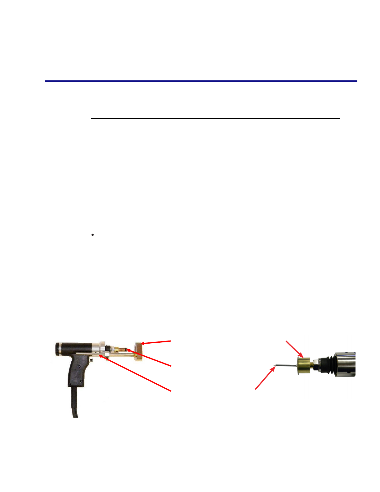
17
Cup Head Welding
Insert Magnetic Chuck Into The Supplied “B” Adapter
And Tighten The Set Screws. (See Figure Above)
Set Spring Pressure Between #1 And #2 By Turning The
Back Cap. (See Figure Above)
Set The Voltage. Recommended Voltage Setting For
Cup Head Pins Is Between 70 And 100 Volts.

18
16
18
TESTINGYOURSETTINGS
Whenyouhaveperformedallofthepresetsasdiscussedinthismanual,itisrecom‐
mendedthatyouperformseveraltestweldswiththesamediameterstudandbase
materialthatyouwillbeusing.Thiswillverifythatallofthesettingsarecorrectto
theresultsyoudesire.Weldingisdonebyplacingthestudintothecollet,andpress‐
ingthestudguntotheworkpiece,compressingthespring.Thisiswhythestudmust
protrudebeyondthefootpieceatleast1/8”.
Holdingthegunperpendiculartotheworkpiece,andaligningthestudtothedesired
positionontheworkpiece,pressdownsothatthefootpieceisflushwiththework
piece(springcompressed),anddepressthetrigger.
Whenremovingthestudgunfromtheweldedstud,alwaysliftthestudgunvertically
fromtheweldedstudinordertomaintainthepropertensionofthecollet.Spreading
thecolletwhenliftingthestudgunfromtheweldedstudwillshortenthelifeofthe
colletandwilleventuallycreateanundesirableweld.
TESTING WELD SETTINGS
Cupheadpinwelding–Whenweldingcupheadpinstherewillnotbeafootpiece
toholdthegunperpendicularthismustbedonemanually.Pressdownonthework
piecesothegunshaisatapprox.½”ofit’smaxtravel(springswillbecompressed
properly)anddepressthetrigger.
16
18
TESTINGYOURSETTINGS
Whenyouhaveperformedallofthepresetsasdiscussedinthismanual,itisrecom‐
mendedthatyouperformseveraltestweldswiththesamediameterstudandbase
materialthatyouwillbeusing.Thiswillverifythatallofthesettingsarecorrectto
theresultsyoudesire.Weldingisdonebyplacingthestudintothecollet,andpress‐
ingthestudguntotheworkpiece,compressingthespring.Thisiswhythestudmust
protrudebeyondthefootpieceatleast1/8”.
Holdingthegunperpendiculartotheworkpiece,andaligningthestudtothedesired
positionontheworkpiece,pressdownsothatthefootpieceisflushwiththework
piece(springcompressed),anddepressthetrigger.
Whenremovingthestudgunfromtheweldedstud,alwaysliftthestudgunvertically
fromtheweldedstudinordertomaintainthepropertensionofthecollet.Spreading
thecolletwhenliftingthestudgunfromtheweldedstudwillshortenthelifeofthe
colletandwilleventuallycreateanundesirableweld.
TESTING WELD SETTINGS

19
17
17
INSPECTINGTHEWELD
Visuallyinspecttheweld.Agoodweldwillresultinanall‐aroundweld,withasmall
visibleamountofweldsurroundingtheflangeofthestud.Toomuchsplatterandthe
weldistoohot,lowerthevoltage.Nosplatterandtheweldistoocold,increasethe
voltage.
Ifyougetweldflashtoonesideofthestudasopposedtoanevenamountaround
thebaseoftheflange,thisiscalled“arcblow”,andcanbesolvedbyrepositioning
thegroundclamporusingadualgroundclamp.
Properweldedstudscanbetestedbyeithertorquingorbendingthestud.The
weldedflangeofthestudshouldstayinplaceusingeithermethod,eventhoughthe
threadedportionofthestudbreaks.Ifthebasematerialisverythin,thenafullslug,
thediameteroftheflangewillpullfromthebasemetalforaproperlyweldedstud.
CDStudWeldingSteps
SET-UP AND WELDING
TESTINGYOURSETTINGS
Whenyouhaveperformedallofthepresetsasdiscussedinthismanual,itisrecom‐
mendedthatyouperformseveraltestweldswiththesamediameterstudandbase
materialthatyouwillbeusing.Thiswillverifythatallofthesettingsarecorrectto
theresultsyoudesire.Weldingisdonebyplacingthestudintothecollet,andpress‐
ingthestudguntotheworkpiece,compressingthespring.Thisiswhythestudmust
protrudebeyondthefootpieceatleast1/8”.
Holdingthegunperpendiculartotheworkpiece,andaligningthestudtothedesired
positionontheworkpiece,pressdownsothatthefootpieceisflushwiththework
piece(springcompressed),anddepressthetrigger.
Whenremovingthestudgunfromtheweldedstud,alwaysliftthestudgunvertically
fromtheweldedstudinordertomaintainthepropertensionofthecollet.Spreading
thecolletwhenliftingthestudgunfromtheweldedstudwillshortenthelifeofthe
colletandwilleventuallycreateanundesirableweld.
TESTING WELD SETTINGS

20
18
18
CD 2301 Order No. BA 92-12-0231A Issue 05.01.10 31
5.8.1
Visual Inspection
A visual inspection must be carried out with each welding element.
Condition Possible cause Corrective actions
Good welded joint
Low spatters around the weld
without outer flaws
The weld pool forms a collar around
the flange of about 1 - 1,5 mm
- Correct parameters - None
Cold weld pool
Gap between flange and workpiece
- Heat input too low
- Plunging speed too low
- No sufficient backing of workpiece
- Increase charging voltage
- Adjust plunging speed correctly
- Provide sufficient backing
Hot weld pool
Many spatters around the weld
- Heat input too high
- Plunging speed too low
- Reduce charging voltage
- Increase plunging speed
One-sided weld pool
One-sided spatter collar
Weld pool came out on one side
- Arc blow effect
- Unsymmetric ground connection
- Welding gun put at an angle
- Take care for symmetrical ground
connection
- Put welding gun vertically to the workpiece
Visual Inspection
5 Stud Welding Procedure
5.8 Checking the Quality of the Weld
TESTINGYOURSETTINGS
Whenyouhaveperformedallofthepresetsasdiscussedinthismanual,itisrecom‐
mendedthatyouperformseveraltestweldswiththesamediameterstudandbase
materialthatyouwillbeusing.Thiswillverifythatallofthesettingsarecorrectto
theresultsyoudesire.Weldingisdonebyplacingthestudintothecollet,andpress‐
ingthestudguntotheworkpiece,compressingthespring.Thisiswhythestudmust
protrudebeyondthefootpieceatleast1/8”.
Holdingthegunperpendiculartotheworkpiece,andaligningthestudtothedesired
positionontheworkpiece,pressdownsothatthefootpieceisflushwiththework
piece(springcompressed),anddepressthetrigger.
Whenremovingthestudgunfromtheweldedstud,alwaysliftthestudgunvertically
fromtheweldedstudinordertomaintainthepropertensionofthecollet.Spreading
thecolletwhenliftingthestudgunfromtheweldedstudwillshortenthelifeofthe
colletandwilleventuallycreateanundesirableweld.
TESTING WELD SETTINGS
Other stud welding products Welding System manuals

stud welding products
stud welding products STUDPRO Series User manual

stud welding products
stud welding products StudPro LiteXI User manual

stud welding products
stud welding products StudPro 2500XI User manual

stud welding products
stud welding products StudPro LiteXI User manual

stud welding products
stud welding products StudPro 2500 User manual


