stud welding products STUDPRO Series User manual

OPERATOR’S MANUAL
STUDPRO SERIES
Capacitor Discharge Stud Welder
MODELS:
StudPro 2500XI
StudPro 2500XIP
StudPro 3125XI
StudPro 3750XI

CONTENTS
Descripon Pages
Safety 2
Specicaons and Features 3
Product Components 4-5
Screen Operaon 6-8
Setup and Welding 9-11
CD Stud Gun Exploded View 12
CD Accessories 13-15

Read the safety noces before operang welder
Electrical
•Due to potenal dangerous electrical input and output the
equipment must be disconnected from all incoming power
when servicing. Do not operate the equipment with the outer
cover removed or with the case open.
•Capacitors store electrical energy, completely discharge before performing any maintenance.
•Do not use uids to clean electrical components as these may penetrate the electrical system
and cause shorts.
•Connecon of the unit into service must be in accordance with the setup procedures as de-
tailed in this manual. Operaon of this equipment must be in accordance with all local, region-
al, and naonal safety codes.
Fire
•During welding, small parcles of hot metal can be expelled. Ensure
that no combusble materials are near the welding area.
Personal Safety
•Arc rays can burn eyes and skin. Wear protecve clothing and eye pro-
tecon when welding.
•Loud noises from welding can damage hearing. Wear earplugs or oth-
er protecve gear, if applicable.
•Fumes and gases expelled during welding can be health hazards. Make sure welding is done in
a well-venlated area.
•Hot metal splaer can cause res and burns. Wear protecve clothing, work in an area free of
combusble materials, and have a re exnguisher nearby.
Maintenance
•All cables must be inspected regularly to ensure that no danger exists from damaged insula-
on or unsafe electrical connecons. Take special note of the cables near the stud gun, this is
where maximum wear occurs.
Training
•Use of this equipment must be limited to authorized personnel only. They must be adequately
trained, and have read and understood everything in this manual.
•The manual must be available to operators at all mes.
Installaon
•Select a site which is capable of supporng the weight of the equipment.
•Select a site which is clear from heavy foot trac areas to avoid tripping hazards.
•Select a site that prevents cable damage from equipment and vehicles.
•Do not hang connecng cables over sharp edges or place near heat sources.
SAFETY
FIRE HAZARD
FROM SPARKS
2

SPECIFICATIONS AND FEATURES
StudPro XI- Capacitor Discharge Stud Welder Series
The StudPro XI series of capacitor discharge stud welders incorporates the latest solid state
technology into a compact, lightweight, and rugged CD stud welder. This full line of equipment is
capable of welding pins, cup head pins, and CD studs ranging from 14-gauge up to 3/8” full-flanged
stainless steel studs.
Specifications
Features
•Intuive Touchscreen Interface with preset values for fast, accurate, and repeatable weld sengs
•Set-Point Discharge: Unit discharges directly to a new set point without needing to discharge com-
pletely
•Universal Input Voltage: Plug and play, no need to re-tap the machine for 110V or 220V input volt-
ages
•Low input voltage capability enables operaon with long extension cords
•Contact and Trigger indicators for fast troubleshoong of hand tool and weld cable maintenance
issues
•Thermal and Voltage protecon indicators to protect the unit from damage due to overheang or
poor input power
•Rigid internal construcon minimizes the possibility of components coming loose during rough han-
dling or operaon
•Hand tool has been ergonomically designed to reduce operator fague for increased welding e-
ciency
•Hand tool has an adjustable internal spring to apply the correct spring pressure for every welding
applicaon
•Hand tool can be congured for B collets, CI (Collet Inserts), Euro collets, or standard tapered
chucks
SPECS StudPro 2500XI StudPro 2500XIP StudPro 3125XI StudPro 3750XI
SIZE 14” L, 10.5” W, 11.5” H
356mm x 267mm x 292mm
WEIGHT
(Power Supply Only) 18 lbs. (8.1Kg) 18 lbs. (8.1Kg) 20.8 lbs. (9.4Kg) 23.4 lbs. (10.6Kg)
CAPACITANCE/ENERGY 76,000µF/1520Ws 76,000µF/1520Ws 114,000µF/2280Ws 152,000µF/3040Ws
WELD RANGE 14Ga - 1/4” Stainless 14Ga - 1/4” Stainless
(including cup head pins) 14Ga - 5/16” Stainless 14Ga - 3/8” Stainless
DUTY CYCLE 18 studs per minute
(1/4” sengs)
18 studs per minute
(1/4” sengs)
14 studs per minute
(5/16” sengs)
10 studs per minute
(3/8” sengs)
PRIMARY POWER
(Universal Input) 85-250 VAC, 6.0-2.0A, 50/60Hz
CHARGE VOLTAGE 35-200 VDC
3
* Specicaons are subject to change without prior nocaon

Front View Back View
Components
1. Touch Screen Interface
2. Weld Ground Connector
3. Cup Pin Weld Ground Connector (Model 250CP only, on all other TW-i models this connector is a
secondary Weld Ground Connector)
4. Stud Gun Control Cable Connector
5. Stud Gun Weld Cable Connector
6. ON/OFF Switch
7. 10A Fuse
8. Manufacturer Model Number and Serial Number Plate
9. Power Cord Socket
PRODUCT COMPONENTS
1
4
25
7
3
6
9
8
4

Internal View
Components
1. Venlaon Fan
2. ON/OFF Switch
3. 10A Fuse
4. AC Inline Filter/Power Cord Socket
5. Capacitor Bank
6. Freewheeling Diodes
7. SCR/Clamp
8. Discharge Resistor
9. Control Board
PRODUCT COMPONENTS
4
3
1
2
5
9
876
5

SCREEN OPERATION
Trigger Indicator
Stud Presets
Metric Stud Mode
Contact Indicator
Stud Preset Screen
Voltage Preset Screen
Charge Indicator
Welding Voltage
Stud Counter
Voltage
Adjustment
Adjustment
Voltage
Presets
Mode Selecon
Voltage
Mode Selecon
6

SCREEN OPERATION
Stud Counter Screen
Reseng the Stud Counter
Stud Counter Reset
•While on the stud counter screen, press the RESET tab located at the boom of the screen.
•The screen will then prompt the user for a conrmaon to clear the stud counter.
•To cancel the reseng of the stud counter, simply press NO on the screen.
•To conrm the reseng of the stud counter, simply press YES on the screen.
Stud Count
7

Screen Status Indicators
SCREEN OPERATION
Status Indicator
8
Status
Indicator Descripon Soluon
OVERTEMP Unit Has Exceeded
Temperature Threshold
Unit needs to cool down before more welds can be
made. Please allow the unit to cool down and clear
the overtemp warning.
UNDER
VOLTAGE
Insucient Input
Power
Unit has detected insucient supply power. Connect
the unit to a more stable power supply.
DC LIMIT ON Duty Cycle Limiter
Acvated
Protects capacitor from overheang by liming the
user to a maximum average duty cycle. This protec-
on only acvates when the set point of the welder
is above 85V. Below 85V there is no limitaon to the
duty cycle of the unit.
ERR: CHRG TIME Max Charge Time
Exceeded
Unit has taken too long to charge and there may be an
issue with the capacitor. With unit powered down en-
sure that all connectors and connecons are ght.
ERR: OUTPUT Capacitor Short
Detecon
Capacitor is not charging properly and the outputs
may be shorted. Check the unit for damage as well as

Connecng the Welding Leads
1. Connect the stud gun weld cable into the gun terminal socket on the front of the welding unit. The
cable end plug has a flat which aligns with a dot on the panel mount socket. Secure the connector
into the panel mount socket, and then turn it clockwise until it locks into proper position. Failure
to properly make these connections could result in damage to the connectors.
2. Connect the weld gun control cable into the center socket connector. The control cable plug has a
large pin and a small pin that match the socket on the unit. Push the plug firmly into the socket
and twist clockwise to secure the plug into the correct position.
3. Connect the ground clamp into the ground terminal socket on the front of the unit, this connec-
tion is identical to step 1.
Connecng the Ground Clamp
1. Prior to securing the clamp, make certain that
the contact area is free of rust, paint, grease, or
any other impuries to ensure a good ground
connecon.
2. Aach the clamp of the welding ground lead to
the work piece.
3. Most applicaons will require only one ground
clamp, but certain applicaons will require an
addional dual clamp.
SETUP AND WELDING
9
Stud Gun Weld
Cable Connecon
Ground Cable Connecon
Stud Gun Control
Cable Connecon

Selecng the Proper Stud Collet (Stud Holder)
Listed below are the common collet styles, the choice between these setups is usually a maer of per-
sonal preference
1. The B collet which is a two-piece assembly (collet and insert). The insert determines how much of
the stud is engaged in the collet.
2. The CI (Collet Insert) which is a single part and the amount of the stud that is engaged is predeter-
mined.
3. Standard Adjustable Chucks have an adjustable internal screw to manually adjust for the engage-
ment of the stud.
The collet sizes are based on the diameter of the stud to be welded.
CD Stud Gun Setup
1. Place the collet into the collet
adapter of the stud gun and set the
locking screws to hold the collet in
place.
2. Mount the two legs and foot piece
onto the stud gun. The collet
should be centered through the
opening of the foot piece.
3. Insert the stud to be welded into
the collet.
4. Adjust the leg and foot piece by sliding it into posion unl approximately 1/8” of the stud pro-
trudes from beyond the foot piece. Lock legs in place with the set screws.
5. The tension seng is adjusted by turning the adjustment cap on the back of the stud gun. On the
side of the stud gun is the tension seng indicator, this displays the tension seng of the internal
spring.
6. The spring tension seng of the stud gun will vary depending on the applicaon. Generally, mild
steel and stainless steel should be set in the 1 to 2 range. Aluminum and other nonferrous metals
will require sengs in the 3 to 5 range.
SETUP AND WELDING
Collet Adapter
Collet
Leg Piece
Adjustment Cap
Tension Indicator
10
Foot Piece

Powering On the Welder
When all of the previous setup steps in this manual are complete the welder can be powered on.
1. Ensure that the power cord is connected to the power cord socket and the supply power.
2. Check the 10A fuse below the ON/OFF switch located on the back of the unit.
3. Use the ON/OFF switch to power the unit on.
Voltage Selecon
•The voltage is determined by the diameter of the stud and the base material thickness. The unit is
programmed with the recommended voltage sengs for various stud sizes. Fine tuning the volt-
age for each applicaon from this starng point is recommended.
•Seng the required weld voltage is achieved by selecng the desired stud size on the screen or
manually seng the voltage by using the + or - arrows.
•Fast voltage selecon can be done from the voltage mode screen. This will replace the preset val-
ues on the screen with voltages in increments of 10V and can be manually adjusted by using the
arrows.
Tesng the Weld Sengs
1. Aer performing all of the setup steps listed in this manual, it is recommended that several test
welds be performed with the same diameter stud and base material used for the applicaon. This
will verify that all of the sengs are correct to achieve the desired results.
2. Welding is done by placing the stud into the collet and pressing the stud gun to the work piece.
3. Hold the gun perpendicular to the work piece, align the stud to the desired locaon, press down
so that the foot piece is ush with the base material, and squeeze the trigger.
4. Spreading the collet nes when liing the stud gun from the welded stud will shorten the life of
the collet and will eventually create an undesirable weld. For maximum collet life remove the
stud gun from the welded stud by pulling the stud gun straight o of the welded stud.
5. Properly welded studs are tested by either torqueing or bending the stud. Using either method
the threaded poron of the stud may break. However, the welded ange of the stud should stay
in place. Addionally, if the base material is very thin, a full slug the diameter of the ange will
pull from the base metal.
Inspecng the Weld
1. Visually inspect the weld. If there is a signicant amount of splaer then the weld is too hot, lower
the voltage. If there is no splaer then the weld is too cold, increase the voltage.
2. A good weld will result in a small, visible, and 360° ashing surrounding the ange of the stud. If
there is weld ash on only one side of the base of the ange, this is called “arc blow,” and can be
solved by reposioning the ground clamp or using a dual ground clamp.
SETUP AND WELDING
11

CD GUN EXPLODED VIEW
12
“B” COLLETS
STUD DIA
PART NO.
3 MM
CDB
-
003M
14 GA
CDB
-
008
12 GA & #4
CDB
-
010
1/8 GA & #5
CDB
-
012
10 GA & #6
CDB
-
013
4 MM
CDB
-
004M
#8
CDB
-
015
#10
CDB
-
018
5 MM
CDB
-
005M
6 MM
CDB
-
006M
.215
CDB
-
021
1/4
CDB
-
025
5/16
CDB
-
031
8 MM
CDB
-
008M
3/8
CDB
-
037
10 MM
CDB
-
010M
SOYER COLLETS
STUD DIA.
PART NO.
#6
CDBS
-
013
4 MM
CDBS
-
004M
#8
CDBS
-
015
#10
CDBS
-
018
5 MM
CDB
S-
005M
6 MM
CDBS
-
006M
1/4
CDBS
-
025
5/16
CDBS
-
031
CAPACITOR DISCHARGE ACCESSORIES
3/8 DIA
1-
3/8
1.781
.390
LENGTH
DIA.
PART NO.
7”
5/16
L-
03107
9”
5/16
L-
03109
14”
5/16
L-
03114
18”
5/16
L-
03118
CD WELDING LEGS
5/16 LEG WASHER
5/16 LEG SCREW
3/8 LEG WASHER
3/8 LEG SCREW
L-
031
-2
L-
037
-1
L-
037
-2
L-
031
-1
13

CAPACITOR DISCHARGE ACCESSORIES
ONE PIECE CONTACT/MAGNETIC CHUCK
PART NO.
039
-
613
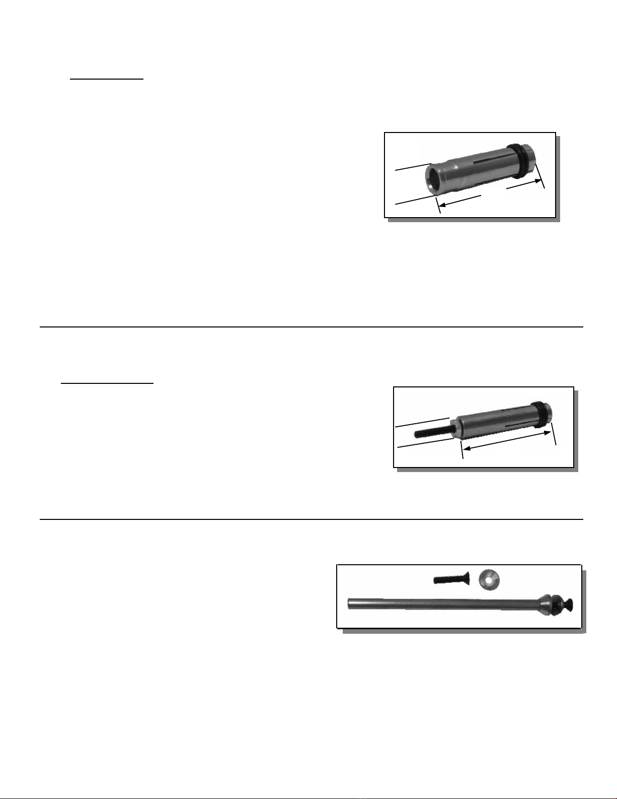
“B” COLLETS PROTECTOR
STUD SIZE
PART NO.
14 GA X 12 GA
028
-
837
10 GA
028
-
838
BODY ONLY
028
-
836
12 GA INSER
T
028
-
834
10 GA INSERT
028
-
835
“B” STOP
STUD
STOP
LENGTH LENGTH
PART NO.
1/4
1-
1/4
033
-
781
3/8
1-
1/8
033
-
782
1/2
1”
033
-
783
5/8 7/8 033
-
784
3/4 3/4 033
-
785
7/8 5/8 033
-
775
1”
1/2 033
-
776
1-
1/8
3/8 033
-
777
1-
1/4
1/4 033
-
778
1-
3/8
(BUTTON STOP)
1/8 033
-
779
UNIVERSAL
033
-
780
SHORT BUTTON STOP
UNIVERSAL “B” STOP
MAGNETIC CHUCK
PART NO.
DESCRIPTION
035
-
301
COMPLETE ASSY
017
-
633
MAGNET ONLY
029
-
615
CONDUCTOR PLATE
039
-
609
INSU
L. TUBE
039
-
610
INSUL. DISC
SCREW
10
-
32 X 7/8
14

TEMPLATE TUBE ADAPTOR
STUD RANGE
PART NO.
14 GA
–
#6
033
-
764
#8
–
3/8
033
-
765
STANDARD SPARK SHIELD
STUD DIA.
X DEPTH
PART NO.
#4 X 1/4
CI
-
010
-
025
#4 X 3/8
CI
-
010
-
037
#4 X 1/2
CI
-
010
-
050
#4 X 1”
CI
-
010
-
100
#6X 1/4
CI
-
013
-
025
#6 X 3/8
CI
-
013
-
037
#6 X 1/2
CI
-
013
-
050
#6 X 5/8
CI
-
013
-
062
#6 X 3/4
CI
-
013
-
075
#6X 1”
CI
-
013
-
10
0
10GA X 1/2
CI
-
014
-
050
10GA X 3/4
CI
-
014
-
075
10GA X 1
CI
-
014
-
100
#8X 1/4
CI
-
015
-
025
#8 X 3/8
CI
-
015
-
037
#8 X 1/2
CI
-
015
-
050
#8 X 5/8
CI
-
015
-
062
#8 X 3/4
CI
-
015
-
075
#8X 1”
CI
-
015
-
100
#10 X 1/4
CI
-
018
-
025
#10 X 3/8
CI
-
018
-
037
#10 X 1/2
CI
-
018
-
050
#10 X 5/8
CI
-
018
-
062
#10 X 3/4
CI
-
018
-
075
#10X 1”
CI
-
018
-
100
1/4 X 1/4
CI
-
025
-
025
1/4 X 3/8
CI
-
025
-
037
1/4 X 1/2
CI
-
025
-
050
1/4 X 5/8
CI
-
025
-
062
1/4 X 3/4
CI
-
025
-
075
1/4 X 1”
CI
-
025
-
100
5/16 X 3/8
CI
-
031
-
037
5/16 X 1/2
CI
-
031
-
050
5/16 X 5/8
CI
-
031
-
062
5/16 X 3/4
CI
-
031
-
075
5/16 X 1”
CI
-
031
-
100
3/8 X 1/2
CI
-
037
-
050
3/8 X
3/4
CI
-
037
-
075
3/8 X 1”
CI
-
037
-
100
COLLETS INSERTS
FOR WELD STUDS
CAPACITOR DISCHARGE ACCESSORIES
STUD RANGE
PART NO.
14 GA
–
10 GA
033
-
769
#6
–
3/8
033
-
769L
VENTED SPARK SHIELD
PART NO.
039
-
481
TEMPLATE I.D.
1” DIA.
30MM
80-40-513
1-
3/4”
1/4 DIA
028-
833
CD FOOT PIECE
PART NO.
028-833
15
This manual suits for next models
4
Table of contents
Other stud welding products Welding System manuals

stud welding products
stud welding products StudPro LiteXI User manual

stud welding products
stud welding products StudPro LiteXI User manual

stud welding products
stud welding products StudPro 2500 User manual

stud welding products
stud welding products StudPro 2500XI User manual

stud welding products
stud welding products StudPro 2500i User manual
Popular Welding System manuals by other brands


schweisskraft
schweisskraft EASY-MIG 201 i MULTI operating instructions

EWM
EWM Picomig 180 puls TGE operating instructions

Simadre
Simadre CT5200D owner's manual

MAGNUM WELDERS
MAGNUM WELDERS TIG200L AC/DC PRO Operation manual

Hot Max
Hot Max PL-25 Operator's manual

Red-D-Arc
Red-D-Arc SuitCase 12VS owner's manual