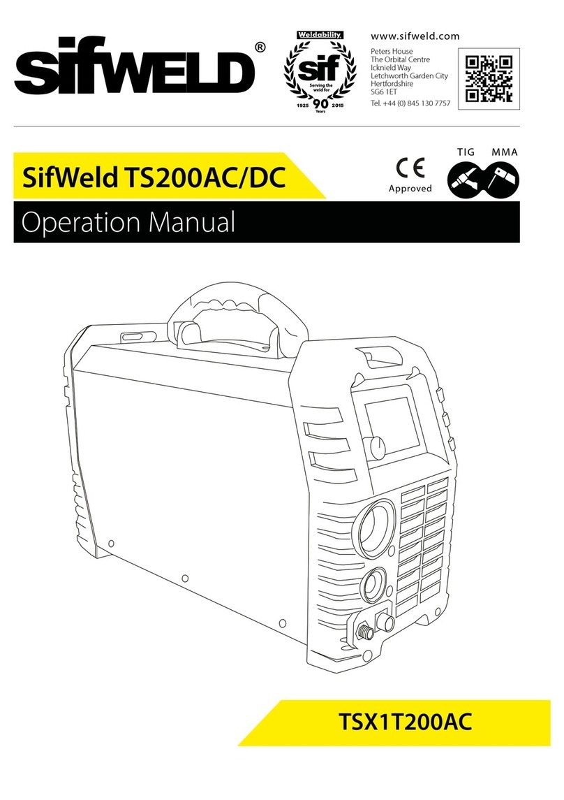
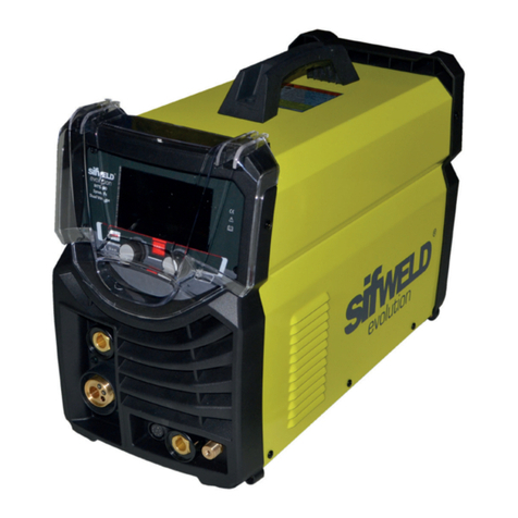
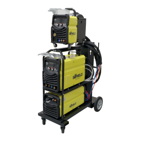
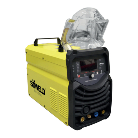
SifWeld Evolution TS200DC User manual

Operation Manual
www.sifweld.com
Peters House
The Orbital Centre
Icknield Way
Letchworth Garden City
Hertfordshire
SG6 1ET
Tel. +44 (0) 345 130 7757
Approved
TIG MMA
TSXE1T200DC
SifWeld Evolution TS200DC

2
DECLARATION OF CONFORMITY
The Low voltage Directive 2006/95/EC of 12 December 2006, entering into force 16 January 2007
The EMC Directive 2004/108/EC, entering into force 20 July 2007
The RoSH Directive 2011/65/EC, entering into force 2 January 2013
Type of Equipment
Welding power source for TIG/TAG, MMA welding
Brand name or trade mark
SifWeld® Evolution
Type designation etc.
TS200DC
Manufacturer or his authorised representative established within the EEA
Name, address, telephone no, fax no
Weldability Sif
Peters House, The Orbital Centre
Icknield Way, Letchworth
Hertfordshire, SG6 1ET
United Kindom
Phone: +44 (0)845 130 7757 Fax: +44 (0)800 970 7757
The following harmonised standard in force with the EEA has been used in the design:
EN60974-1- Arc welding equipment- Part 1: Welding power sources
EN60974-10 Arc welding equipment - Part 10: Electromagnetic Compatibility (EMC) requirements
Additional information: restrictive use, Class A equipment, intended for use in locations other than residential
By signing this document, the undersigned declares as manufacturer, or the manufacturer’s authorised
representative established within the EEA, that the equipment in question complies with the safety
requirements stated above.
WEEE Directive & Product Disposal
At the end of its serviceable life, this product should not be treated as household
or general waste. It should be handed over to the applicable collection point for
the recycling of electrical and electronic equipment, or returned to the supplier for
disposal.
Place and Date
Letchworth, UK
01-04-2015
Position
Quality Manager
Weldability Sif
Signiture
Keith Mullan

3
Safety Guidelines
These general safety norms cover both arc welding machines and plasma cutting machines unless
otherwise noted. The equipment must only be used for the purpose it was designed for. Using it in any
other way could result in damage or injury and in breach of the safety rules. Only suitably trained and
competent persons should use the equipment. Operators should respect the safety of other persons.
Prevention against electric shock
The equipment should be installed by a qualified person and in accordance with current standards in
operation. It is the user’s responsibility to ensure that the equipment is connected to a suitable power
supply. Consult with your utility supplier if required. If earth grounding of the work piece is required,
ground it directly with a separate cable. Do not use the equipment with the covers removed. Do not
touch live electrical parts or parts which are electrically charged. Turn o all equipment when not in use.
Cables (both primary supply and welding) should be regularly checked for damage and overheating. Do
not use worn, damaged, under sized or poorly jointed cables. Ensure that you wear the correct protec-
tive clothing, gloves, head and eye protection. Insulate yourself from work and ground using dry insulat-
ing mats or covers big enough to prevent any physical contact with the work ground. Never touch the
electrode if you are in contact with the work ground, or another electrode from a dierent machine.
Do not wrap cables over your body. Ensure that you take additional safety precautions when you are
welding in electrically hazardous conditions such as damp environments, wearing wet clothing, and
metal structures. Try to avoid welding in cramped or restricted positions. Ensure that the equipment is
well maintained. Repair or replace damaged or defective parts immediately. Carry out any regular main-
tenance in accordance with the manufacturer’s instructions.
Safety against fumes and welding gases
Locate the equipment in a well-ventilated position. Keep your head out of the fumes. Do not breathe
the fumes. Ensure the welding zone is in a well-ventilated area. If this is not possible provision should be
made for suitable fume extraction. If ventilation is poor, wear an approved respirator. Read and under-
stand the Material Safety Data Sheets (MSDS’s) and the manufacturer’s instructions for metals, consum-
able, coatings, cleaners, and de-greasers. Do not weld in locations near any de-greasing, cleaning, or
spraying operations. Be aware that heat and rays of the arc can react with vapours to form highly toxic
and irritating gases. Do not weld on coated metals, unless the coating is removed from the weld area,
the area is well ventilated, and while wearing an air-supplied respirator. The coatings on many metals
can give o toxic fumes if welded.
Prevention against burns and radiation
Arc rays from the welding process produce intense, visible and invisible (ultraviolet and infrared) rays
that can burn eyes and skin. Wear an approved welding helmet fitted with a proper shade of filter lens
to protect your face and eyes when welding or watching. Wear approved safety glasses with side shields
under your helmet. Never use broken or faulty welding helmets. Always ensure there are adequate
protective screens or barriers to protect others from flash, glare and sparks from the welding area. Ensure
that there are adequate warnings that welding or cutting is taking place.

4
Wear suitable protective flame resistant clothing. The sparks and spatter from welding, hot work pieces,
and hot equipment can cause fires and burns. Welding on closed containers, such as tanks, drums, or
pipes, can cause them to explode. Accidental contact of electrode to metal objects can cause arcs,
explosion, overheating, or fire. Check and be sure the area is safe and clear of inflammable material
before carrying out any welding.
Protection against noise
Some welding and cutting operations may produce noise. Wear safety ear protection to protect your
hearing.
Protection from moving parts
When the machine is in operation, keep away from moving parts such as motors and fans. Moving
parts, such as the fan, may cut fingers and hands and snag garments. Protections and coverings may
be removed for maintenance and controls only by qualified personnel, after first disconnecting the
power supply cable. Replace the coverings and protections and close all doors when the intervention
is finished, and before starting the equipment. Take care to avoid getting fingers trapped when loading
and feeding wire during set up and operation. When feeding wire be careful to avoid pointing it at other
people or toward your body. Always ensure machine covers and protective devices are in operation.
Precautions against fire and explosion
Avoid causing fires due to sparks and hot waste or molten metal. Ensure that appropriate fire safety
devices are available near the cutting / welding area. Remove all flammable and combustible materials
from the cutting / welding zone and surrounding areas. Do not cut/weld fuel and lubricant containers,
even if empty. These must be carefully cleaned before they can be cut/welded. Always allow the cut/
welded material to cool before touching it or placing it in contact with combustible or flammable
material. Do not work in atmospheres with high concentrations of combustible fumes, flammable gases
and dust. Always check the work area half an hour after cutting to make sure that no fires have begun.
Risks due to magnetic fields
The magnetic fields created by high currents may aect the operation of pacemakers or electronically
controlled medical equipment. Wearers of vital electronic equipment should consult their physician
before beginning any arc welding, cutting, gouging or spot welding operations. Do not go near welding
equipment with any sensitive electronic equipment as the magnetic fields may cause damage.
RF Declaration
Equipment that complies with directive 2004/108/EC concerning electromagnetic compatibility (EMC)
and the technical requirements of EN60974-10 is designed for use in industrial buildings and not those
for domestic use where electricity is provided via the low voltage public distribution system. Diculties
may arise in assuring class A electromagnetic compatibility for systems installed in domestic locations
due to conducted and radiated emissions. In the case of electromagnetic problems, it is the
responsibility of the user to resolve the situation. It may be necessary to shield the equipment and fit
suitable filters on the mains supply.

5
LF Declaration
Consult the data plate on the equipment for the power supply requirements. Due to the elevated
absorbency of the primary current from the power supply network, high power systems aect the
quality of power provided by the network. Consequently, connection restrictions or maximum
impedance requirements permitted by the network at the public network connection point must be
applied to these systems. In this case the installer or the user is responsible for ensuring the equipment
can be connected, consulting the electricity provider if necessary.
Materials and their disposal
The equipment is manufactured with materials, which do not contain any toxic or poisonous
materials dangerous to the operator. When the equipment is scrapped, it should be dismantled
separating components according to the type of materials. Do not dispose of the equipment with
normal waste. The European Directive 2002/96/EC on Waste Electrical and Electronic Equipment states
the electrical equipment that has reached its end of life must be collected separately and returned to an
environmentally compatible recycling facility.
Handling of Compressed gas cylinders and regulators
All cylinders and pressure regulators used in welding operations should be handled with care.
Never allow the electrode, electrode holder or any other electrically “hot” parts to touch a cylinder.
Keep your head and face away from the cylinder valve outlet when opening the cylinder valve.
Always secure the cylinder safely. Never deface or alter any cylinder.
The following signs and explanations are to remind the user of the potential
risks involved and the dangers of misuse or mistreatment of the welding
machine.
!
RUNNING PARTS MAY BE DANGEROUS!
Keep away from running components,
including the fan.
BE AWARE OF SPARKS AND SPATTER
Wear protective clothing, such as leather
gloves, Flame retardant overalls, boots and
eyewear.
DO NOT TOUCH THERMAL COMPONENTS!
Thermal components may cause severe burns
when in contact with unprotected skin.
ELECTRIC SHOCKS CAN KILL!
Never touch electrical parts. Keep the
equipment in good condition, replace
damaged parts, undertake regular
maintenance according to the instructions.

6
1. Preface 7
1.1 General 7
1.2 Introduction 8
1.3 Technical Specications 9
1.4 Overview of Machine 10
2. Control Panels 11
2.1 MMA Display 12
2.2 HF/Lift TIG Display 13
2.3 TIG SPOT Display 15
3. Installation 18
3.1 Torch Switch Control 21
3.2 Pedal switch Control 22
4. Operation 23
5. Troubleshooting 24
6. Maintenance 25
7. Warranty 26
Contents

7
1. Preface
Congratulations on choosing your SifWeld Evolution TS200DC welding machine.
Used correctly, SifWeld products can signicantly increase the productivity of your welding, and provide
years of economical service. This operating manual contains important information on the use,
maintenance and safety of your SifWeld product. Please read the manual carefully before using the
equipment for the rst time. For your own safety and that of your working environment, pay particular
attention to the safety instructions in the manual.

For more information on SifWeld products, consult an authorised SifWeld dealer, or visit the SifWeld web
site at www.sifweld.com. The specications presented in this manual are subject to change without prior
notice.
Important notes
Items in the manual that require particular attention in order to minimise damage and personal harm
are indicated with the ’NOTE!’ notation. Read these sections carefully and follow their instructions.
Disclaimer
While every eort has been made to ensure that the information contained in this guide is accurate and
complete, no liability can be accepted for any errors or omissions. We reserve the right to change the
specication of the product described at any time without prior notice. Do not copy, record, reproduce
or transmit the contents of this guide without prior permission.
1.1 General

8
A professional, microprocessor-controlled inverter welding power source for DC TIG & MMA applications.
The use of IGBT technology providing a compact and lightweight machine that is feature rich.
High Frequency ignition and High Speed Pulse and the complete range of fully adjustable parameters
normally expected on a professional TIG welding machine.
Features
• Full digital control with large colour LCD for showing and changing all welding parameters
• Power factor correction
• 230V and 110V
• Spot / repeat / high speed pulse function
• Generator friendly
• Foot pedal available.
1.2 Introduction

9
1.3 Technical Specications
10
485 × 160 × 295
Duty cycle (40oC, 10mins)
Cooling
Net weight (Kg)
Dimensions (mm)
TIG
DC DC
Up slope/Down slope (S)
Pre/Post Flow (S)
Welding current range (A)
Power factor
Rated input power (KW)
Rated input current (A)
SifWeld Evolution TS200DC
Power source 1-110V±10%, 50/60Hz
Max no load voltage (V)
Pulse Frequency (HZ)
Pulse Width Range (%)
Eciency (%)
0.99
24.1
0.5~999
5~95
80
1-230V±10%, 50/60Hz
19.8 29.6
TIG MMA
2.6 4.6
10~130 10~200
0.1~2.0/ 0.0~10.0
Circuit breaker
Protection class
D32A
IP21S
AF
DC
MMA
DC
31.9
4.2 6.8
66.9 67.2
0~10
60% 180A
30% 200A
90% 130A
100% 145A
60% 145A
100% 75A 100% 110A
15% 130A
60% 65A
100% 50A

10
INSTALLATION & OPERATION
1
§3 Installation & Operation
§3.1 Layout for Front and Rear panel
1 Negative output: The welder’s negative polarity output.
2 Shield gas connector: Is connected to the gas input pipe of torch.
3 Aero socket: Is connected to torch switch control wire.
4 Positive output: The welder’s positive polarity output.
5 Power source switch: Switch to “ON”, the welder is turned on, while switch to
“OFF”, the welder is turned off.
6 Power source input: To connect power source.
7 Shield gas input joint: To connect one head of the gas hose while the other head is
connected to argon gas cylinder.
1.4 Overview of Machine
Front View
Power Source Front Panel Layout
1 Negative output
2 Shield gas connector
3 Control socket
4 Positive output
Rear View
5 Power source switch
6 Power source mains input
7 Shield gas input joint
INSTALLATION & OPERATION
1
§3 Installation & Operation
§3.1 Layout for Front and Rear panel
1 Negative output: The welder’s negative polarity output.
2 Shield gas connector: Is connected to the gas input pipe of torch.
3 Aero socket: Is connected to torch switch control wire.
4 Positive output: The welder’s positive polarity output.
5 Power source switch: Switch to “ON”, the welder is turned on, while switch to
“OFF”, the welder is turned off.
6 Power source input: To connect power source.
7 Shield gas input joint: To connect one head of the gas hose while the other head is
connected to argon gas cylinder.

11
2. Control Panels
INSTALLATION & OPERATION
1
§3.2 Layout for Control panel
§3.2.1 Control panel
1. Screen: It will show all welding parameters, such as welding voltage, welding current
and other parameters set.
2. SETING button.*
3. Parameters select/adjust knob.*
4. Trigger mode selection: Press it to select 2T or 4T trigger mode.
*Denotes more detailed explanation of function to follow.
Further Controls Explained
SETING button (2)
Press it to lock “SETING” interface and press again or wait for 2s to unlock. In
“SETING” interface, you can select welding mode or function mode by press the
parameters select/adjust knob (3).
Parameters select/adjust knob (3)
When locking the “SETING” interface, you can select welding mode: TIG LIFT, TIG HF
or MMA by turning the knob. Similarly, you can select function mode: PULSE, NO
PULSE or SPOT (Spot is only available in TIG HF welding mode) by turning the knob.
When unlocking the “SETING” interface, you can press the knob to select parameters,
such as welding current, Peak current, Base current, Pulse frequency and Pulse width.
Rotate it to adjust parameters’ value.
1. Screen
It will show all welding parameters, such as welding voltage, welding current and other parameters set.
2. SETTING button.
3. Parameters select/adjust knob.
4. Trigger mode selection
Press it to select 2T or 4T trigger mode.
Further Controls Explained
SETTING button (2)
Press it to lock “SETTING” interface and press again or wait for 2s to unlock. In“SETING” interface, you can
select welding mode or function mode by press the parameters select/adjust knob (3).
Parameters select/adjust knob (3)
When locking the “SETTING” interface, you can select welding mode: TIG LIFT, TIG HF or MMA by turning
the knob. Similarly, you can select function mode: PULSE, NO PULSE or SPOT (Spot is only available in TIG
HF welding mode) by turning the knob.
When unlocking the “SETTING” interface, you can press the knob to select parameters, such as welding
current, Peak current, Base current, Pulse frequency and Pulse width. Rotate it to adjust parameters’value.

12
2.1 MMA Display
INSTALLATION & OPERATION
1
§3.2.2 MMA display introduction
1. SETTING button: Press it to lock “SETING” interface, then turn the Parameters
select/adjust knob to select MMA welding mode.
2. Parameters select/adjust knob: turn it to select welding mode or value of current,
Hot start and Arc force. Press it to select parameters.
3. Value display: Here is value of the currently selected parameter, such as current,
Hot start and Arc force.
4. MMA current: Press the knob to confirm and turn knob to adjust. Range: 0~200A.
5. Hot start: Press the knob to confirm and turn knob to adjust. Range: 0~10.
6. Arc force: Press the knob to confirm and turn knob to adjust. Range: 0~10.
1. SETTING button
Press it to lock “SETTING” interface, then turn the Parameters select/adjust knob to select
MMA welding mode.
2. Parameters select/adjust knob
Turn it to select welding mode or value of current, Hot start and Arc force. Press it to select parameters.
3. Value display
Here is value of the currently selected parameter, such as current, Hot start and Arc force.
4. MMA current
Press the knob to conrm and turn knob to adjust. Range: 0~200A.
5. Hot start
Press the knob to conrm and turn knob to adjust. Range: 0~10.
6. Arc force
Press the knob to conrm and turn knob to adjust. Range: 0~10.

13
INSTALLATION & OPERATION
1
§3.2.3 HF/LIFT TIG display introduction
1. SETING button: Press it to lock “SETING” interface, then turn the Parameters
select/adjust knob to select TIG LIFT or TIG HF welding mode.
2. Parameters select/adjust knob: turn it to select welding mode or value, such as
current, Down Slope and Post-Flow. Press it to select parameters or function mode.
3. Trigger mode button: You can select 2T or 4T trigger mode.*
4. Function: When locking “SETING” interface, you can press the parameters
select/adjust knob to select function, such as PULSE, NO PULSE and SPOT. SPOT
is only available in TIG HF welding mode.
5. Value display: Here is value of the currently selected parameter, such as current,
Down Slope and Post-Flow.
6. TIG parameter display.*
*Denotes more detailed explanation of function to follow.
Further Controls Explained
Trigger mode button (3)
2T Mode
The trigger is pulled and held on to activate the welding circuit, when the trigger is
2.2 HF/LIFT TIG Display
1. SETTING button
Press it to lock “SETTING” interface, then turn the Parameters select/adjust knob to select TIG LIFT or TIG
HF welding mode.
2. Parameters select/adjust knob
Turn it to select welding mode or value, such as current, Down Slope and Post-Flow. Press it to select
parameters or function mode.
3. Trigger mode button
You can select 2T or 4T trigger mode.
4. Function
When locking “SETTNG” interface, you can press the parameters select/adjust knob to select function,
such as PULSE, NO PULSE and SPOT. SPOT is only available in TIG HF welding mode.
5. Value display
Here is value of the currently selected parameter, such as current, Down Slope and Post-Flow.
6. TIG parameter display
Further Controls Explained
Trigger mode button (3)
2T Mode
The trigger is pulled and held on to activate the welding circuit, when the trigger is released, the
welding circuit stops.

14
4T Mode
This is known as ’latching’mode. The trigger is pulled once and released to activate the welding circuit,
pulled and released again to stops the welding circuit. This function is useful to longer welds as the
trigger is not required to be held on continuously. TIG series of welding machines also has more current
control options that can be used in 4T mode.
TIG parameter display (6)
In this mode, a total of 10 parameters can be adjusted.
Pre-Flow setting
Pre-Flow controls the period shielding gas will ow for when the torch is triggered before the arc starts.
This purges the work area of atmospheric gas which could contaminate the weld before the weld starts.
Unit (S) and setting range (0.1~2.0S).
Pre-Current setting
Available in 4T trigger mode, sets a welding current 5~100% of the peak current (main welding current)
activated when the trigger is held on to ‘latch’ the trigger before the main weld current is started. Once
the trigger is released, the current will go through the upslope period if it is set, to the peak current.
Up Slope setting
When the trigger is activated, the welding current will increase gradually over the time selected up to
the set peak current. Unit (S) and setting range (0.0~10.0S).
Peak Current setting
Set the peak current. Unit (A) and setting range (10~200A).
Base current setting
Only be available when pulse mode is selected. Set the current of the low/base pulse. Unit (A) and
setting range (10~200A).
Pulse Frequency setting
Only be available when pulse mode is selected. Set the rate that the welding output alternates between
the peak and base current settings. Unit (Hz) and setting range (0.5~999Hz).
Pulse Width setting
Only be available when pulse mode is selected. Set the time proportion as a percentage between the
peak current and base current when using pulse mode. Neutral setting is 50%, the time period of the
peak current and base current pulse is equal. Higher pulse duty setting will give greater heat input, while
lower pulse duty will have the opposite eect. Unit (%) and setting range (5~95%).
Down Slope setting
When the trigger is released, the welding current will reduce gradually over the time selected down to 0.
This allows the operator to complete the weld without leaving a ‘crater’ at the end of the weld pool. Unit
(S) and setting range (0.0~10.0S).

15
2.3 TIG Spot Display
INSTALLATION & OPERATION
1
§3.2.4 TIG Spot display introduction
1. Pre-Flow: 0.1~2.0s.
2. Current: 10~200A.
3. Ton display: 0.1~1.0s.
4. Toff display: OFF~10.0s.
5. Post-Flow: 0.0~10.0s.
1. Pre-Flow: 0.1~2.0s.
2. Current: 10~200A.
3. Ton display: 0.1~1.0s.
4. To display: OFF~10.0s.
5. Post-Flow: 0.0~10.0s.
Post current setting
Available in 4T trigger mode only, sets a welding current 5~100% of the peak welding current activated
when the trigger is held on to ‘unlatch’the trigger before the weld is nished. If downslope is set, the
current will go through the downslope period before going to the end current set. When the trigger is
released, the arc will stop.
Post-Flow setting
Controls the period of time the shielding gas continues to ow for after the arc is stopped. This
protects the weld area and torch tungsten from contamination while it is still hot enough to react with
atmospheric gases, after the weld is nished. Unit (S) and setting range (0.0~10.0S).
Pulse welding
Pulse welding mode switches the welding output between a high and low current output in a cyclical
manner. When used correctly this function has substantial benets in the TIG welding process including
greater weld penetration for less work heat input and greater control of the weld pool.

16
2T MODE
The trigger is pulled and held on to activate the welding circuit, when the trigger is released, the
welding circuit stops. This function without the adjustment of start current and crater current is suitable
for the Re-tack welding, transient welding, thin plate welding and so on.
INSTALLATION & OPERATION
1
2T Mode
The trigger is pulled and held on to activate the welding circuit, when the trigger is
released, the welding circuit stops.
This function without the adjustment of start current and crater current is suitable for the
Re-tack welding、transient welding、thin plate welding and so on.
Introduction:
(1) 0: Press the gun switch and hold it. Electromagnetic gas valve is turned on. The
shielding gas stars to flow.
(2) 0~t1: Pre-gas time (0.1~2.0s)
(3) t1~t2: Arc is ignited and the output current rises to the setting welding current (Iwor
Ib) from the min welding current.
(4) t2~t3: During the whole welding process, the gun switch is pressed and held without
releasing.
Note: Select the pulsed output, the base current and welding current will be outputted
alternately; otherwise, output the setting value of welding current;
(5) t3: Release the gun switch, the welding current will drop in accordance with the
selected down-slope time.
(6) t3~t4: The current drops to the minimum welding current from the setting current (Iw
or Ib), and then arc is turned off.
(7) t4~t5: Post-gas time, after the arc is turned off. You can adjust it (0.0~10s) through
turnning the knob on the front panel.
(8) t5: Electromagnetic gas valve turned off, the shield gas stops to flow, and welding is
finished.
Introduction
1. 0: Press the gun switch and hold it. Electromagnetic gas valve is turned on. The shielding gas stars to
ow.
2. 0~t1: Pre-gas time (0.1~2.0s)
3. t1~t2: Arc is ignited and the output current rises to the setting welding current (Iw or Ib) from the
min welding current.
4. t2~t3: During the whole welding process, the gun switch is pressed and held without releasing.
Note: Select the pulsed output, the base current and welding current will be outputted alternately;
otherwise, output the setting value of welding current.
5. t3: Release the gun switch, the welding current will drop in accordance with the selected down-slope
time.
6. t3~t4: The current drops to the minimum welding current from the setting current (Iw or Ib), and
then arc is turned o.
7. t4~t5: Post-gas time, after the arc is turned o. You can adjust it (0.0~10s) through turnning the knob
on the front panel.
8. t5: Electromagnetic gas valve turned o, the shield gas stops to ow, and welding is nished.

17
4T MODE
This is known as ’latching’mode. The trigger is pulled once and released to activate the welding circuit,
pulled and released again to stops the welding circuit. This function is useful to longer welds as the
trigger is not required to be held on continuously. TIG series of welding machines also has more current
control options that can be used in 4T mode.
The start current and crater current can be pre-set. This function can compensate the possible crater
that appears at the beginning and end of the welding. Thus, 4T is suitable for the welding of medium
thickness plates.
PANEL FUNCTIONS & DESCRIPTIONS
1
welding circuit, pulled and released again to stops the welding circuit. This function is
useful to longer welds as the trigger is not required to be held on continuously. TIG series
of welding machines also has more current control options that can be used in 4T mode.
The start current and crater current can be pre-set. This function can compensate the
possible crater that appears at the beginning and end of the welding. Thus, 4T is suitable
for the welding of medium thickness plates.
Introduction:
(1) 0: Press and hold the gun switch, Electromagnetic gas valve is turned on. The
shielding gas stars to flow;
(2) 0~t1: Pre-gas time (0.1~2.0S);
(3) t1~t2: Arc is ignited at t1 and then output the setting value of start current;
(4) t2: Loosen the gun switch, the output current slopes up from the start current;
(5) t2~t3: The output current rises to the setting value (Iwor Ib), the upslope time can be
adjusted;
(6) t3~t4: Welding process. During this period, the gun switch is loosen;
Note: Select the pulsed output, the base current and welding current will be outputted
alternately; otherwise, output the setting value of welding current;
(7) t4: Press the torch switch again, the welding current will drop in accordance with the
selected down-slope time.
(8) t4~t5: The output current slopes down to the crater current. The downslope time
can be adjusted;
(9) t5~t6: The crater current time;
(10) t6: Loosen the gun switch, stop arc and keep on argon flowing;
(11) t6~t7: Post-gas time can be set by the post-gas time adjustment knob on the front
Introduction
1. 0: Press and hold the gun switch, Electromagnetic gas valve is turned on. The shielding gas stars to ow.
2. 0~t1: Pre-gas time (0.1~2.0S);
3. t1~t2: Arc is ignited at t1 and then output the setting value of start current;
4. t2: Loosen the gun switch, the output current slopes up from the start current;
5. t2~t3: The output current rises to the setting value (Iw or Ib), the upslope time can be adjusted;
6. t3~t4: Welding process. During this period, the gun switch is loosen;
Note: Select the pulsed output, the base current and welding current will be outputted alternately;
otherwise, output the setting value of welding current;
7. t4: Press the torch switch again, the welding current will drop in accordance with the selected down-
slope time.
8. t4~t5: The output current slopes down to the crater current. The downslope time can be adjusted;
9. t5~t6: The crater current time;
10. t6: Loosen the gun switch, stop arc and keep on argon owing;
11. t6~t7: Post-gas time can be set by the post-gas time adjustment knob on the front

18
3. Installation
Unpacking
Check the packaging for any signs of damage. Carefully remove the machine and retain the packaging
until the installation is complete.
Location
The machine should be located in a suitable position and environment. Care should be taken to avoid
moisture, dust, steam, oil or corrosive gases. Place on a secure level surface and ensure that there is
adequate clearance around the machine to ensure natural airflow.
Input connection
Before connecting the machine you should ensure that the correct supply is available. Details of the
machine requirements can be found on the rating plate of the machine or in the technical parameters
shown in the manual. The equipment should be connected by a suitably qualified competent person.
Always ensure the equipment has a proper grounding. Never connect the machine to the mains supply
with the panels removed.
Output connections
In general when using manual arc welding electrodes the electrode holder is connected to the positive
terminal and the work return to the negative terminal. Always consult the electrode manufacturer’s
data sheet if you have any doubts. When using the machine for TIG welding the TIG torch should be
connected to the negative terminal and the work return to the positive terminal.

19
MMA Welding
Two sockets are available on this welding machine. For MMA welding the electrode holder is shown be
connected to the positive socket, while the earth lead (work piece) is connected to the negative socket,
this is known as DCEP. However various electrodes require a dierent polarity for optimum results and
careful attention should be paid to the polarity, refer to the electrode manufacturer’s information for the
correct polarity.
DCEP: Electrode connected to“+”output socket.
DCEN: Electrode connected to “-”output socket.
MMA (DC): Choosing the connection of DCEN or DCEP according to the dierent electrodes. Please refer
to the electrode manual.
MMA (AC): No requirements for polarity connection..
INSTALLATION & OPERATION
1
panel (0.0~10S);
(12) t7: Electromagnetic valve is closed and stop argon flowing. Welding is finished.
§3.3 Installation & Operation for MMA welding
§3.3.1 Set up installation for MMA Welding
Connection of Output Cables
Two sockets are available on this welding machine. For MMA welding the electrode
holder is shown be connected to the positive socket, while the earth lead (work piece) is
connected to the negative socket, this is known as DCEP. However various electrodes
require a different polarity for optimum results and careful attention should be paid to the
polarity, refer to the electrode manufacturer's information for the correct polarity.
DCEP: Electrode connected to “+” output socket.
DCEN: Electrode connected to “-” output socket.
MMA (DC): Choosing the connection of DCEN or DCEP according to the different
electrodes. Please refer to the electrode manual.
MMA (AC): No requirements for polarity connection.
(1) Connect the earth lead to “-”, tighten clockwise;
(2) Connect the earth clamp to the work piece. Contact with the work piece must be firm
1. Connect the earth lead to“-”, tighten clockwise
2. Connect the earth clamp to the work piece. Contact with the work piece must be rm
3. Connect the electrode lead to “+”, tighten clockwise
4. Each machine is equipped with a power cable should be based on the input voltage welding power
cable connected to the appropriate position, not to pick the wrong voltage
5. With the corresponding input power supply terminal or socket good contact and prevent oxidation
6. With a multi meter measure the input voltage is within the uctuation range
7. The power ground is well grounded.

20
TIG Welding
1. Insert the earth cable plug into the positive socket on the front of the machine and tighten it.
2. Plug the welding torch into the negative socket on the front panel, and tighten it.
3. Connect the gas line of TIG Gun to outlet gas connector on the front of the machine.
4. Connect the control cable of torch switch to 12 pin socket on the front of the machine.
5. Connect the gas regulator to the Gas Cylinder and connect the gas line to the Gas Regulator. Check
for Leaks!
6. Connect the gas line to the machine inlet gas connector via the quick push lock connector located on
the rear panel. Check for Leaks!
NOTE: Air cooling mode without cooling device and the water pipe is not needed for the air cooling
mode.
7. Connect the power cable of welding machine with the output switch in electric box on site. Turn on
the power switch.
INSTALLATION & OPERATION
2
§3.4 Installation & Operation for TIG welding
§3.4.1 Set up installation for TIG Welding
(1) Insert the earth cable plug into the positive socket on the front of the machine and
tighten it.
(2) Plug the welding torch into the negative socket on the front panel, and tighten it.
(3) Connect the gas line of TIG Gun to outlet gas connector on the front of the machine.
(4) Connect the control cable of torch switch to 12 pin socket on the front of the machine.
(5) Connect the gas regulator to the Gas Cylinder and connect the gas line to the Gas
Regulator. Check for Leaks!
(6) Connect the gas line to the machine inlet gas connector via the quick push lock
connector located on the rear panel. Check for Leaks!
NOTE: Air cooling mode without cooling device,and the water pipe is not needed for
the air cooling mode.
(7) Connect the power cable of welding machine with the output switch in electric box on
site. Turn on the power switch.
This manual suits for next models
1
Table of contents
Other SifWeld Welding System manuals

SifWeld
SifWeld MTS 200 User manual

SifWeld
SifWeld Evolution MTS200 SYN User manual

SifWeld
SifWeld CUT 40 Digital User manual

SifWeld
SifWeld Evolution CUT40 Air User manual

SifWeld
SifWeld TS200AC/DC TSX1T200AC User manual

SifWeld
SifWeld Evolution MTS500 ROBOT User manual

SifWeld
SifWeld Evolution MTS400 SYN User manual

SifWeld
SifWeld Evolution TS320ACDC User manual

SifWeld
SifWeld TSX1D300MTS User manual

SifWeld
SifWeld Evolution MTS500 DP User manual