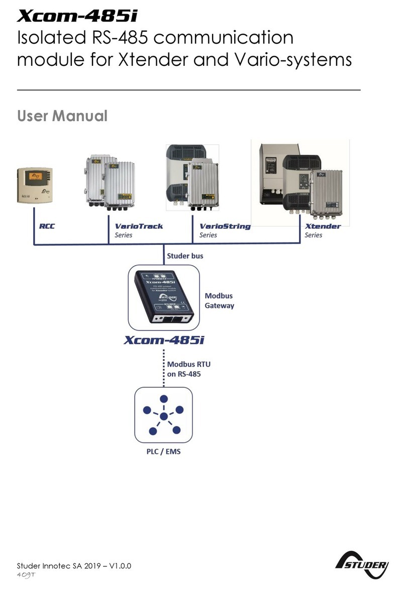
Studer Xcom-SMS User manual

Studer Innotec SA 2015 –V 1.0.0
4O9Q
Communication module Xcom-SMS
User manual

Studer Innotec SA
Xcom-SMS
2 V 1.0.0 User manual
COMMUNICATION MODULE XCOM-SMS: USER MANUAL
ABOUT THE SOFTWARE
This document applies to software versions V1.4.0 or higher of the Xcom-SMS. It is possible to
update the product with the latest software version available on "www.studer-
innotec.com/support".
COMPATIBILITY WITH STUDER PRODUCTS
The Xcom-SMS operates in Xtender systems (with products such as Xtender, VarioTrack,
VarioString, BSP, RCC-02/--03); however, it is incompatible with the following products: Xcom-232i,
Xcom-LAN, Xcom-GSM.
LEGAL NOTICE
The use of Studer Innotec SA devices is the responsibility of the customer in all cases. Studer Innotec
SA reserves the right to make any modification to the product without prior notice.
PRODUCT RECYCLING
The Xcom-SMS conforms to the European directive 2011/65/EC on
hazardous substances and does not contain the following elements:
lead, cadmium, mercury, hexavalent chrome, PBB or PBDE.
To dispose of this product, please use the service for collection of
electrical waste and observe all applicable obligations according to
the place of purchase.

Studer Innotec SA
Xcom-SMS
User manual V 1.0.0 3
TABLE DE MATIÈRES
1Introduction......................................................................................................................................... 5
1.1 The communication module Xcom-SMS .....................................................................................5
1.2 Conventions ......................................................................................................................................5
1.2.1 Symbols ......................................................................................................................................5
1.3 Warranty and liability.......................................................................................................................5
1.3.1 Disclaimer of warranty ............................................................................................................5
1.3.2 Disclaimer of liability ................................................................................................................6
1.3.3 Compatibility.............................................................................................................................6
1.4 Safety precautions ...........................................................................................................................6
1.4.1 Generalities ...............................................................................................................................6
1.4.2 Warnings ....................................................................................................................................6
2EC declaration of conformity............................................................................................................ 7
3Material needed for the installation................................................................................................. 8
3.1 Contents of the Xcom-SMS communication set ........................................................................8
3.2 Additional items................................................................................................................................8
4Installation ........................................................................................................................................... 8
4.1 Configuration of the Xcom-SMS ....................................................................................................8
4.2 Wiring and automatic power-up ................................................................................................11
5Blinking codes and push button ..................................................................................................... 15
6How to use the communication module .............................................................................................. 18
6.1 Overview..........................................................................................................................................18
6.2 Secure access.................................................................................................................................18
6.3 Acknowledgement of receipt .....................................................................................................19
6.4 SMS format.......................................................................................................................................19
7SMS Commands ............................................................................................................................... 20
7.1 Changing the access code of the Xcom-SMS.........................................................................20
7.2 Changing the language...............................................................................................................21
7.3 Activation/deactivation of SMS replies......................................................................................22
7.4 Remove the Xcom-SMS subscriptions ........................................................................................22
7.5 Operating report by SMS ..............................................................................................................24
7.5.1 Contents of the report ..........................................................................................................24
7.5.2 Subscribe/Unsubscribe to reports .......................................................................................24
7.5.3 Configuration of sending the operating report ...............................................................26
7.5.4 Receive a list of subscribers to the report .........................................................................27
7.5.5 Receive a report instantly ....................................................................................................27
7.6 Event based SMS ............................................................................................................................29
7.6.1 Subscribe/Unsubscribe to events........................................................................................29
7.6.2 Sending events by category ...............................................................................................30
7.6.3 Sending events by number ..................................................................................................31
7.6.4 Receive the list of event subscribers ..................................................................................31
7.6.5 Receive the state of transmission of events......................................................................32
7.7 State ON / OFF of a device..........................................................................................................33
7.7.1 Turn ON / OFF a device .......................................................................................................33
7.7.2 Receive the state ON / OFF for a device..........................................................................34
7.8 Commands of the Xtender's auxiliary relays by SMS ...............................................................34
7.9 Access to the system's parameters by SMS...............................................................................35
7.9.1 Writing parameters ................................................................................................................36

Studer Innotec SA
Xcom-SMS
4 V 1.0.0 User manual
7.9.2 Reading parameters .............................................................................................................37
7.10 Access to the system's user information by SMS.......................................................................37
7.10.1 Reading user information .....................................................................................................37
7.11 Ask for help ......................................................................................................................................38
8Changing SIM card .......................................................................................................................... 39
9Trouble-shooting............................................................................................................................... 39
10 Error messages in relation with the Xcom-SMS............................................................................. 41
11 Datalogger ........................................................................................................................................ 42
11.1 Functioning ......................................................................................................................................42
11.2 Analysis and visualization of the data with the Xtender data analysis tool .......................42
12 Software(s) updating........................................................................................................................ 43
12.1 Updating process ...........................................................................................................................43
13 Dimensions ........................................................................................................................................ 44
14 Mounting............................................................................................................................................ 45

Studer Innotec SA
Xcom-SMS
User manual V 1.0.0 5
1INTRODUCTION
1.1 THE COMMUNICATION MODULE XCOM-SMS
This user manual contains a complete description of the functioning of the communication
module Xcom-SMS.
The communication module Xcom-SMS makes it possible to access systems with Studer Innotec
devices through SMS (Short Message Service) sent from a mobile phone, a web site, etc. It
provides the user with a tool that gives easy access to the system in order to know its current state
and to control it remotely reducing the necessity to physically go to the site.
1.2 CONVENTIONS
1.2.1 Symbols
This symbol is used to indicate a risk of material damage.
This symbol is used to indicate information that is important or which serves to
optimize your system.
1.3 WARRANTY AND LIABILITY
During production and assembly, each Xcom-SMS undergoes several controls and tests. These are
carried out in full respect of fixed procedures. Each Xcom-SMS is given a serial number allowing a
perfect follow-up of the controls, in conformity with the specific data of every device. For this
reason, it is very important to never remove the descriptive sticker bearing the serial number. The
production, the assembly and tests of each Xcom-SMS are entirely carried out in our factory in
Sion (CH). The warranty of this product depends on the strict following of the instructions in this
manual. The warranty period for the Xcom-SMS is 5 years as from its production date.
1.3.1 Disclaimer of warranty
No warranty will be applied for damages caused by handling, operation or actions that are not
described in this manual. Damages arisen from the following events are not covered by the
warranty:
Overvoltage on the device.
Liquid in the device or oxidation due to condensation.
Failures due to a fall or to a mechanical shock.
Modifications made without the explicit authorization of Studer Innotec SA.
Nuts or screws partially or insufficiently tightened during installation or maintenance.
Damages due to atmospheric overvoltage (lightning).
Damages due to transport or improper packaging.
Disappearance of original marking items.

Studer Innotec SA
Xcom-SMS
6 V 1.0.0 User manual
1.3.2 Disclaimer of liability
Installation, commissioning, use and maintenance of this device cannot be supervised by the
company Studer Innotec SA. For this reason, we do not accept any liability for damages, costs or
losses generated either by an installation that is not conforming to the prescriptions, by a defective
operation or by poor maintenance. The use of this device is under the responsibility of the end-
user. This device is neither designed nor guaranteed for the supply of life support applications or
any other critical application with potential risks for human beings or for the environment. We shall
assume no liability for patent infringement or other third party rights involved in the use of this
device.
1.3.3 Compatibility
Studer Innotec SA guarantees the compatibility of the software updates with the hardware for
one year, starting from the date of purchase. The updates are no longer guaranteed beyond this
date and a hardware upgrade may be required. Please contact your reseller for any additional
information on compatibility.
1.4 SAFETY PRECAUTIONS
1.4.1 Generalities
Carefully read all safety instructions before proceeding with the installation and commissioning of
the device. Failure to follow these instructions might constitute a lethal physical danger but can
also damage the functionalities of the device. Therefore this manual should always be kept close
to the device.
For any installation, the local and national norms and regulations in force must be
strictly followed.
1.4.2 Warnings
Wherever the system, the person in charge of installation and commissioning must know
the safety measures and the prescriptions in force in the country. Therefore, the whole
maintenance must be carried out by qualified personnel.
All components connected to this device must be conforming to the laws and
regulations in force. Persons without a written authorization from Studer Innotec SA are
forbidden to do any changes, modifications or repairs whatsoever. Regarding authorized
modifications and replacements, only genuine components shall be used.
This device is meant for indoor use only and must under no circumstances be exposed to
rain, snow or any other humid or dusty environment.
If used in motor vehicles, this device must also be protected against vibrations by shock
absorbing components.

Studer Innotec SA
Xcom-SMS
User manual V 1.0.0 7
2EC DECLARATION OF CONFORMITY
The communication module Xcom-SMS described in this manual meets the requirements
specified in the following EC directives and norms:
Low voltage directive 2006/95/CE: EN 60950:2005
EMC directive 2004/108/CE: EN61000-6-1:2005
RoHS directive: 2011/65/UE
CH - 1950 Sion, January 2015
Studer Innotec SA (R. Studer)
Studer Innotec SA contact details
Studer Innotec SA
Rue des Casernes 57
CH - 1950 Sion
Switzerland
+41(0) 27 205 60 80
+41(0) 27 205 60 88
info@studer-innotec.com
www.studer-innotec.com

Studer Innotec SA
Xcom-SMS
8 V 1.0.0 User manual
3MATERIAL NEEDED FOR THE INSTALLATION
3.1 CONTENTS OF THE XCOM-SMS COMMUNICATION SET
The communication set Xcom-SMS contains the following material:
3.2 ADDITIONAL ITEMS
In addition to the material delivered with the communication set the use of an Xcom-SMS
necessitates a micro SIM card as well as a mobile phone that can send and receive SMS
messages. During installation there is also need for a computer and a slot headed screwdriver.
4INSTALLATION
There are two phases in installing an Xcom-SMS:
1. Configuration of the Xcom-SMS, using the Xcom Configurator software supplied on
the micro SD card
2. Wiring of the module
4.1 CONFIGURATION OF THE XCOM-SMS
Your Xcom-SMS module needs to know the PIN code of your micro SIM card in order to send SMS
messages, just as a mobile phone. You also have to enter the phone number linked with this micro
SIM card. During this phase you may also enter a test mobile phone number to which test SMS
messages, operating reports of your system and alarms will be sent.
To store these data in the Xcom-SMS you will have to use the micro SD card supplied with the
device.
1 Quick guide
1 Xcom-SMS with antenna
1 communication cable, 2m
1 micro SD card with adapter (contains
product documentation in pdf-format as
well as the Xcom-SMS configuration
software.)
Mounting plate

Studer Innotec SA
Xcom-SMS
User manual V 1.0.0 9
1. Insert the micro SD card (using the adapter) and run the Xcom Configurator available on the
micro SD card.
The following window will open:
2. In the field "SD Card Drive", choose the drive of your SD card from the drop-down menu (in the
example: F:/XCOM CONFIG). The configuration files for your Xcom-SMS will be generated on
this drive.

Studer Innotec SA
Xcom-SMS
User manual V 1.0.0 11
1. PIN Code:
Here you should enter the PIN code supplied with your micro SD card. It's a code of 4 to 6
digits. This code is mandatory except if it has been removed, using a phone, or if the SIM
card comes without a PIN code.
2. SIM Card Phone Number:
Here you should enter the phone number assigned to your micro SIM card. We
recommend to enter the international phone number format indicating the country
code from where the system will be operating. In the example above the country code is
+41, which is the country code for Switzerland.
3. Owner Phone Number:
Here you should enter the phone number to which messages and reports from your
system will be sent as well as the automatic message that confirms that the configuration
has been successful. It is recommended to use an international format with the country
code of the country where the system will be operating.
4. User Key:
Here you should enter the access code that you would like to use when accessing the
system in the future. This code (<key>) will be necessary when sending messages to your
system. Find out more about its signification and format, in chapter 6.2. This code is
mandatory and you will need it in order to generate the configuration files. Remember to
write down this code, without it it's impossible to communicate with your Xcom-SMS.
5. When all requested fields are filled out, press "Generate" to create the configuration files.
5. A window will automatically confirm the successful file generation. Click on OK, the
configuration of your SD card is completed.
You may now remove the SD card from your computer and insert it into the Xcom-SMS.
4.2 WIRING AND AUTOMATIC POWER-UP
Wiring the system is easy but requires meticulous attention in order to facilitate the smooth
functioning of the system. Once connected to your system the power-up will be automatic.
The SD card delivered with the Xcom-SMS contains a software update for all the
devices of the system (Xtender/VarioTrack/VarioString/…). When the Xcom-SMS is
connected, it will verify the software version of each device connected to the
communication bus. If the software version on the SD card is more recent than the
existing version on the devices, they will be updated which will cause a restart (with
interruption of operation) in the corresponding devices.

Studer Innotec SA
Xcom-SMS
12 V 1.0.0 User manual
1. Insert the micro SIM card. It is a push-push connector (push to insert and push to eject). Insert
the micro SIM card until you hear a "click" from the spring.
2. Insert the micro SD card that contains the configuration files of your Xcom-SMS (see chapter
4.1). It is a push-push connector (push to insert and push to eject). Insert the micro SD card
until you hear a "click" from the spring.
3. Adjust the antenna (rotate the antenna and manually tighten it).
4. Check the termination on the device to which you will connect the Xcom-SMS. If the system
contains several devices it is necessary to connect the Xcom-SMS to one of the ends of the
system. Connect your module with the supplied cable to a free communication connector
in the system.
Figure 4.1: Connection schematics for Xcom-SMS
(example 1: system with one other device)

Studer Innotec SA
Xcom-SMS
User manual V 1.0.0 13
Figure 4.2: Connection schematics for Xcom-SMS
(example 2: system with several devices)
The start-up is automatic once the Xcom-SMS is connected and powered by your system. The
Xcom-SMS will perform different sequences indicated by the bi-coloured LED (red/green) situated
next to the communication cable. These sequences are summarized below:
1. Start-up of the Xcom-SMS. The bi-coloured LED will blink orange (green and red at the same
time) 2x repeatedly.
2. If your system requires an update the communication module will perform it automatically
depending on the contents of the SD card. It can be the update of one configuration file or
a complete system update. It can be quick or long, depending on its contents and can take
from a few seconds to several minutes (update of the entire system). When an update starts
the bi-coloured LED lights up for 1.5 seconds in orange, then keeps blinking in red.
3. Once the update is completed the module will access the micro SIM card and the
configuration files on your SD card. This sequence is indicated by the LED blinking in orange 2x
repeatedly.
With one other device in the system the termination on the other device should be
put to T as in "Terminated". See figure 4.1.
An incorrect setting of the terminations can lead to an erratic running of the system
or impede its updating.
With more than two devices in the system all Studer devices should be put to O as
"Open" apart from the devices at the ends of the communication chain. These
devices should be put to T as "Terminated". The Xcom-SMS does not have a
termination since it has only one communication cable port. See figure 4.2
An incorrect setting of the link ends can lead to an erratic running of the system or
impede its updating.
By default, the termination is terminated (position T) on each of Studer Innotec SA's
products.

Studer Innotec SA
Xcom-SMS
14 V 1.0.0 User manual
4a. If everything functions well and the GSM connection has been established with your mobile
phone operator the module will start blinking in green 2x repeatedly. It will send a confirmation
SMS of the start-up to the phone number entered in the Xcom Configurator in the field "Owner
Phone Number". If you would like to send another test-SMS manually, briefly push the button
of the Xcom-SMS.
4b. If the system has not been able to complete properly the start-up, it will blink red 2x repeatedly.
No SMS will be sent. If you have a remote control (RCC-02/-03) an error message will be
displayed indicating the problem (if the error has been identified). For instance, if there is no
micro SIM card inserted into the Xcom-SMS, the RCC will display:
Error (146):
SIM card missing

Studer Innotec SA
Xcom-SMS
User manual V 1.0.0 15
5BLINKING CODES AND PUSH BUTTON
Figure 5.1: Front and isometric view of the Xcom-SMS
Key
Description
(a)
Push button
This button enables 3 functions.
1. Pressing the button for less than 0.8 s:
Sends a test-SMS to the phone number set in the Xcom-configuration. The
signalisation LED (b) does not indicate this function and behaves
normally.
2. Pressing the button for 0.8 s to 3 s:
No function. However the signalisation LED (b) is turned off. If you let go of
the button now nothing will happen and the Xcom-SMS will continue to
function normally.
3. Pressing the button for 3 s to 6 s:
Saves all files on the SD card. You should let go of the button when the
signalisation LED (b) is green.
4. Pressing the button for 6 s to 9 s:
Deletes the Xcom-SMS configuration (no more events or reports will be
sent). You should let go of the button when the signalisation LED (b) is red.
This action will not change the access code.
Pressing the button for more than 9 seconds does nothing. After 9 s the
signalisation LED (b) behaves normally and you can let go of the button without
any changes in behaviour. For example, if you wish to save all files on the SD
card but you accidentally hold the button more than 6 s, you can keep holding
the button more than 9 s, then let go without changing any functions.
(b)
Bicoloured signalisation LED green/red (cable side)
The signalisation LED indicates different functions using colour and frequency of
blinking. Hereafter each function is described in detail.
Push button (absolute priority)
Pressing the push button will have a direct impact on the blinking of the LED. The
push button has an absolute priority on the functioning of the LED over other
indications described hereafter. These are listed by priority, from the highest to
the lowest priority.

Studer Innotec SA
Xcom-SMS
16 V 1.0.0 User manual
SD card inserted (high priority)
When a SD card is inserted the red and green signalisation LEDs blinks
simultaneously (orange) during 1.5 seconds and indicates that the card is
read/inserted correctly.
Update of the Xcom-SMS
During update of the Xcom-SMS (as soon as a micro SD card containing an
update has been inserted) the signalisation LED blinks red.
The updating process may take between 3 and 15 minutes. During this
period it is possible that the signalisation LED will stop for an instant. The
updating process is finalised as soon as the red signalisation LED stops
blinking for at least 20 seconds. Never interrupt an updating process.
Error detected during the update process or during data logging
If the Xcom-SMS detects an error, the red signalisation LED is continuously lit.
Micro SD card is full
If the Xcom-SMS detects that the micro SD card is full, the red signalisation LED
will flash.
Fatal errors of the Xcom-SMS
These errors will prevent the communication between the system and your
phone. The red signalisation LED will blink 2x repeatedly if the Xcom-SMS is facing
one of the following errors:
The micro SD card is not configured
The SIM card is not inserted
The PIN code of the SIM card is wrong
The SIM card is locked. Use a mobile phone and the PUK code to unlock
the SIM card.
Impossible to connect to the phone network.
In either case you will have to solve the problem (see chapter "Troubleshooting")
and then disconnect and reconnect the Xcom-SMS to its Xtender system
(disconnect and then reconnect the cable).
Occasional errors of the Xcom-SMS
The red signalisation LED blinks 2x once. These occasional errors are not serious
and will not prevent the use of the Xcom-SMS. For instance, the Xcom-SMS has
not been able to send an SMS.
Start-up of the Xcom-SMS
The signalisation LED blinks 2x repeatedly in orange (green and red LED lit
simultaneously) during the start-up of the system. During this period the Xcom-
SMS is not yet in operation.
In operation (low priority)
The green signalisation LED blinks 2x repeatedly if the Xcom-SMS is in operation
and none of the above states are present.

Studer Innotec SA
Xcom-SMS
User manual V 1.0.0 17
(c)
Micro SD card reader
The card reader allows for the insertion of a micro SD card to log data (chap. 11
–p. 42) or for system updates (chap. 12 –p. 43).
(d)
CAN connectors
This connector allows to connect the Xcom-SMS with an Xtender system in order
to fully use its functions.
Figure 5.2: Back and isometric view of the Xcom-SMS
Key
Description
(e)
GSM antenna connector
This connector allows to connect the antenna to the module. The antenna
should be carefully tightened manually.
(f)
Green signalisation LED for GSM communication
This LED indicates the state of communication with the telephone network. The
blinking codes are as follows:
1. LED off
- the modem is not in operation
2. Fast flashes
- searching for the network
- not yet registered at the network
- about to lose the network (feeble signal)
3. Slow blinking
- registered to the network, complete service
4. LED continuously lit
- ongoing call
(g)
Micro SIM card connector
This is the connector to insert the micro SIM card that you will have to buy from
your telephone operator.

Studer Innotec SA
Xcom-SMS
18 V 1.0.0 User manual
6HOW TO USE THE COMMUNICATION MODULE
6.1 OVERVIEW
A large number of the system's functions are accessible using the Xcom-SMS. However, it is not
possible to access all functionalities of the system remotely or though SMS.
The Xcom-SMS module includes the following functionalities:
Operating reports by SMS
Events sent by SMS
Start / Stop a device
Control the auxiliary relays
Access to the parameters (Read / Write)
Reading the user information
Changing the access code
Subscribe / Unsubscribe to reports and system alarms
Changing the language
Help
6.2 SECURE ACCESS
The Xcom-SMS module protects your system with an access code in order to avoid that a third
party takes control over a system by knowing its phone number. This access code, indicated <key>
in this document, is a unique code of 6 characters. These characters can be composed of
numbers ('0' to '9'), upper case or lower case letters ('a' to 'z' et 'A' to 'Z'). The access code is case
sensitive.
As it is not possible to identify the sender of an SMS command, the access code has to be used in
the beginning of each SMS. The access code must be followed by a space in order to be
acknowledged.
By default the access code is set to: 123456
It is highly recommended to change the access code to guarantee the security of your system
(see the command "newkey").
If an SMS is sent using an incorrect access code <key>, the system will send an error message in
return if it's possible to identify the sender. The error message has this format:
Xcom-SMS Error: wrong key
Attention, in case of loss of the code the configuration has to be repeated from
scratch using the Xcom Configurator available on the micro SD card.
Your installer may also reset the access code if necessary.
The number of consecutive error messages has been limited to 5. Thereafter the
Xcom-SMS is blocked during 24h before taking in consideration any new SMS.
This function prevent the system from being hacked by the scanning method which
would create important SMS costs (in reply) by the Xcom-SMS.

Studer Innotec SA
Xcom-SMS
User manual V 1.0.0 19
6.3 ACKNOWLEDGEMENT OF RECEIPT
Each message received by the Xcom-SMS will generate a return message that acknowledges
whether the SMS has been processed. It is possible to deactivate the return message function with
the command "smsrsp", see chapter 0.
If an SMS is sent with incorrect formatting or in a format unknown to the Xcom-SMS, the system will
return an error message by SMS if it is possible to identify the sender. The error message has this
format:
Xcom-SMS Error : wrong sms format
6.4 SMS FORMAT
SMS messages sent to the Xcom-SMS must have the following format:
The SMS should always start with the system access code <key>. The access code is
followed by one or several commands.
The following characters are authorized in the SMS commands:
oLower case letters 'a' to 'z'
oUpper case letters 'A' to 'Z'
oNumbers '0' à '9'
oSpecial characters; namely:
'.'
','
'?'
'='
When the Xcom-SMS receives an SMS it starts by verifying the access code <key>. If the access
code is correct the commands contained in the SMS will be controlled and then executed.

Studer Innotec SA
Xcom-SMS
20 V 1.0.0 User manual
7SMS COMMANDS
The commands will enable you to communicate with your remote system. The commands are
described on the following pages. At the end of the description of each command an example
of the SMS command is given.
All commands are in English. The commands are short and meaningful.
For some commands the number of arguments is limited to 10. To make a
command with more than 10 parameters you will have to send an additional SMS.
It is not possible to use the same command twice in the same SMS.
7.1 CHANGING THE ACCESS CODE OF THE XCOM-SMS
It is recommended that the user change the access code to the communication module Xcom-
SMS. Use the following command to change the access code <key>.
Format : newkey <key>
<key> Mandatory
User access code of 6 characters (case sensitive)
Accepted characters: 0-9, a-z, A-Z
Example of the command "newkey":
Example of SMS using the
command "newkey".
Example of SMS with an error in
the command "newkey" (the
code must contain 6
characters).
Command
Functioning of the Xcom-SMS
newkey 1a2B3c
The access code of the Xcom-SMS is now 1a2B3c. The
code by default 123456 is no longer valid. All SMS sent to
the Xcom-SMS should hereafter start with the new access
code 1a2B3c.
123456 newkey
1a2B3c
Xcom-SMS
- cmd newkey: success
123456 newkey
1a2B3cw346hd
Xcom-SMS
- cmd newkey: wrong
format
Table of contents
Other Studer Control Unit manuals
Popular Control Unit manuals by other brands

Festo
Festo CDVI5.0 Assembly instructions

Parker
Parker U Series Maintenance instructions

NuAire
NuAire IAQ-V125 installation manual
Dieffematic
Dieffematic CENTRALE Mini quick start guide

Elster
Elster Kromschroder VMF operating instructions
Herberholz
Herberholz AK/DVGW Information for Assembling, Operating and servicing

