manuals.online logo
Brands
  1. Home
  2. •
  3. Brands
  4. •
  5. Parker
  6. •
  7. Control Unit
  8. •
  9. Parker U Series Technical specifications

Parker U Series Technical specifications

Maintenance
Instructions
MI-104 Revision -
Parker Hannifin Corporation
Instrumentation Valve Division
Jacksonville, Alabama
1
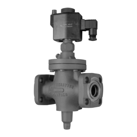
U Series Needle Valve
Table I: Maximum Working Pressure and Temperature
Valve Packing Maximum Pressure and Temperaure Maximum Temperature and Pressure
Grafoil ® 6000 psig at 70 °F 1545 psig at 1200 °F
41.4 MPa at 21 °C 10.7 MPa at 649 °C
PTFE 6000 psig at 70 °F 4280 psig at 450 °F
41.4 MPa at 21 °C 29.5 MPa at 204 °C
Al ays consult your authorized Parker representative if questions arise. The arro on the Valve Body indicates the
normal direction of flo .
Table II: Packing Nut
Hex Wrench Sizes and Tightening Re uirements
Valve Size Hex Wrench Size PTFE Stem Packing Graf il ® Stem Packing
U6 3/4 inch 125 in-lbs 10.4 ft-lbs
(14.1 N-m) (37.3 N-m)
U12 15/16 inch 150 in-lbs 33.3 ft-lbs
(16.8 N-m) (44.8 N-m)
U16 1-1/8 inch 50 ft-lbs 50 ft-lbs
(67.8 N-m) (67.8 N-m)
Parker Hannifin Corporation
Instrumentation Valve Division
Jacksonville, Alabama
MI-104
Figure 1: U Series Needle Valve
Cross Sectional Vie
Table III: Lock Nut
Hex Wrench Sizes and Tightening Re uirements
Valve Size Hex Wrench Size T rque Requirement
U6 model 3/4 inch 125 in-lbs (14.1 N-m)
U12 model 15/16 inch 150 in-lbs (16.8 N-m)
U16 model 1 1/4 inch 150 in-lbs (16.8 N-m)
Table IV: Bonnet Nut
Hex Wrench Sizes and Tightening Re uirements
Valve Size Hex Wrench T rque Requirements
U6 model 15/16 inch 65 ft-lbs. (88 N-m)
U12 model 1-1/4 inch 75 ft-lbs. (101 N-m)
U16 model 1-1/2 inch 100 ft-lbs. (135 N-m)
PANEL MOUNTED VALVES
The panel must have a through-hole diameter of correct diameter. The maximum panel thickness is 1/4 inch (6.4
mm).
U6 model 41/64 inch (16.2 mm)
U12 model 53/64 inch (21.0 mm)
U16 model 1-1/64 inch (25.8 mm)
1.Remove the Handle by unthreading the Set Scre in the side of the Handle ith the follo ing size allen rench:
U6 model 3/32 inch
U12 model 3/32 inch
U16 model 1/8 inch
2.Grip the Packing Nut ith a rench as listed in Table II. With another rench (as listed in Table III), loosen the
Lock Nut.
3.Remove both the Packing Nut and the Lock Nut by unthreading until completely removed.
4.Insert the Valve through the hole in the panel and assemble the Panel Nut onto the Bonnet finger-tight. For assembly,
grip the large Bonnet Nut ith a hex rench as listed in Table IV and tighten the Panel Nut securely.
CAUTION: Do not grip the Valve Body or loosen the Bonnet Nut.
5.Thread the Lock Nut onto the Bonnet. Thread the Packing Nut onto the Bonnet and tighten in accordance ith
Table II.
6.Tighten the Lock Nut against the Packing Nut in accordance ith Table III.
7.Re-install the Handle ith the Set Scre onto the Stem.
2
Parker Hannifin Corporation
Instrumentation Valve Division
Jacksonville, Alabama
MI-104
3
DISASSEMBLY
MAKE CERTAIN THE SYSTEM IN WHICH THE VALVE IS INSTALLED IS DRAINED AND/OR EXHAUSTED OF ALL
PRESSURES BEFORE VALVE DISASSEMBLE OR REMOVAL OCCURS.
1.Verify that the Union Bonnet Valve Maintenance Kit being used is appropriate for the Valves size, handle, stem
packing configuration and service requirements. Al ays contact your authorized Parker representative if any ques-
tions arise.
2.Remove the Handle by unthreading the Set Scre in the side of the Handle ith the follo ing size allen rench.
U6 model 3/32 inch
U12 model 3/32 inch
U16 model 1/8 inch
3.Loosen the Locknut, located directly under the Packing Nut, by turning clock ise ith the follo ing size hex
rench:
U6 model 3/4 inch
U12 model 15/16 inch
U16 model 1-1/4 inch
4.Remove and save the Packing Nut, located directly under the Handle, by turning counter-clock ise ith the follo -
ing size hex rench:
U6 model 3/4 inch
U12 model 15/16 inch
U16 model 1-1/8 inch
5.Remove and save the Locknut from the Bonnet
6.Remove and discard the Lube Seal from ithin the Packing Nut.
7.If applicable, remove the Valve Body from its panel mounting hole by turning the Panel Nut counter-clock ise and
removing it from the Bonnet.
8. Remove and save the Bonnet Nut, located directly above the Body, by turning counter-clock ise ith the follo ing
size hex rench:
U6 model 15/16 inch
U12 model 1-1/4 inch
U16 model 1-1/2 inch
9. Remove the Bonnet/Stem Assembly from the Valve Body.
10. Press the Stem UP to disengage the Stem Guide hex from the Bonnet.
11. While carefully securing the Valve Stem, remove the Stem Guide from the Bonnet using the follo ing size hex
rench:
U6 model 3/8 inch
U12 model 9/16 inch
U16 model 11/16 inch
12. Slide the Valve Stem from the Bonnet by applying a minimal amount of force (i.e. hand pressure) on the Handle
end of the Valve Stem and pushing to ards the seat end.
13. Remove the Packing Washers and the Packing from ithin the Bonnet. The Upper Packing Washer should fall out
easily. The Packing must be pushed out ith a thin probe or ire. After this is removed the lo er Packing Washer
should also fall out.
NOTE: If the valve is Grafoil® packed make certain the entire packing is removed since it may break-up during removal.
14. Discard the appropriate components from the valve consistent ith the ne components ithin the Valve Kit.
Additi nal Step (U16 nly)
15. Using a pick or thin flat headed scre driver remove the metal o-ring from ithin the Valve Body. Insure care not
to damage the o-ring groove.
Parker Hannifin Corporation
Instrumentation Valve Division
Jacksonville, Alabama
MI-104
4
REASSEMBLY
Make certain all parts are free f dirt r ther c ntaminati n bef re starting reassembly f the Valve.
1.Clamp the Body in a vise.
2.U16 nly: Install the Metal O-Ring into the o-ring groove in the Valve Body
3.Insert the three packing components into the Bonnet in the follo ing order ith the first item being placed at the
bottom of the Bonnet:
Packing Washer
Stem Packing
Packing Washer
4.Insert the Stem Guide into the Bonnet, use it to push the packing components to the bottom of the Bonnet. Insert
the Stem Guide hex into the hex-shaped slot at the top of the Bonnet.
5.Apply a liberal amount of lubricant, as consistent ith the Valves service requirements, to the Stem Sub-Assembly
threads. Al ays contact your authorized Parker representative is questions arise.
NOTE: Every thread must be covered ith lubricant.
6.Refer to Figures 2 and 3. Carefully install the Stem Sub-Assembly into the Bonnet from the lo er end until hand-
tight.
7.Apply a liberal amount of lubricant, as consistent ith the Valves service requirements, to the Body threads, as ell
as to the surface area here the Bonnet fits up against the interior of the Bonnet Nut. Al ays contact your
authorized Parker representative if questions arise.
8.Place the hand-tight Bonnet and Stem Sub-Assembly from Step 6 into the Body. Torque the Bonnet Nut onto the
Body using the hex rench size and torque specified in Table IV.
9.This Step only applies to Valves ith an optional Panel Nut, else proceed to Step 10.
Insert the Body into its panel mounting hole. Thread the Panel Nut clock ise onto the Bonnet until the Valve is
secure in the mounting panel.
10. Place the Lube Seal over the Stem to the top of the Stem Guide.
11. Apply a small amount of lubricant, as consistent ith the Valves service requirements, to the Bonnet upper threads
and the top of the Stem Guide.
NOTE: A minimum of the upper four (4) Bonnet threads must be covered ith lubricant !
12. Place the Locknut on the Bonnet and thread it do n near the Panel Nut. Place the Packing Nut over the Bonnet.
Tighten in accordance ith Table II.
13. Tighten the Locknut against the Packing Nut. Tighten in accordance ith Table III.
14. Re-install the Handle ith the Set Scre onto the Stem.
15. Install the Handle on the Stem Sub-Assembly. Secure the Handle ith the Set Scre , and tighten the Set Scre
to 15 In-lbs torque, using a 3/32 inch allen rench. Verify the Handle is tightly fastened.
16. Turn the Bar Handle through at least one (1) Open and Close cycle to verify proper operation of the Stems
threads.
17. Reject and rebuild any Union Bonnet Valve exhibiting rough or irregular Stem operation. Al ays contact your
authorized Parker representative if questions arise.
Parker Hannifin Corporation
Instrumentation Valve Division
Jacksonville, Alabama
MI-104
5
Figure 3: Size 16 Union Bonnet Valve Exploded View
Figure 2: Size 6 & Size 12 Union Bonnet Valve Exploded View
MI-104
Parker Hannifin Corporation
Instrumentation Valve Division
Jacksonville, Alabama
6
VALVE CONNECTOR MAKE-UP INSTRUCTIONS
MALE AND FEMALE PIPE PORTS
Wrench flats are provided on the Valve Body. It is recommended a smooth- jawed wrench or vise be used to grip the Valve Body.
1. On the male threaded part of the connection apply a high quality pipe joint compound or PTFE tape made for this purpose. When PTFE tape is
used it is recommended two full turns of tape be applied. PTFE tape should not be overhanging or covering the first thread
2. Engage the Valve and the other component part together until hand-tight.
3. With a proper wrench holding both the Valve and the component part continue to tighten to achieve a leak-tight joint.
ULTRASEAL CONNECTIONS
1. Insert the proper O-Ring into the UltraSeal fittings O-Ring groove. Position the UltraSeal gland sealing face against the O-Ring and then advance
the Nut to a finger-tight position.
2. A positive seal is obtained by advancing the Nut no less than 1/4 turn from the finger-tight position. Proper UltraSeal make-up is achieved when
a sharp rise in required application torque occurs which indicates proper seal face contact and O-Ring seal compression into the UltraSeal
groove.
VACUSEAL CONNECTIONS
1. A positive seal is obtained by advancing the Nut 1/8 turn from the finger-tight position.
2. A new gasket should be installed upon each fitting re-make to insure system pressure integrity.
TUBE FITTING CONNECTIONS
1. Insert the tube into the Valve port until the tube bottoms out in the Valve Body. Care should be exercised to insure the tube is properly aligned with
the Valve Body and port.
2. Normal make-up for US Customary port sizes 1 thru 3 (1/16 thru 3/16 inch) and SI port sizes 2 thru 4 (2 thru 4 mm) is 3/4 turn from finger tight.
Normal make-up for US Customary port sizes 4 thru 16 (1/4 thru 1 inch) and SI port sizes 5 thru 25 (5 thru 25 mm) is 1 1/4 turn from finger tight.
For larger port sizes consult Parker Ferrule Presetting Tool Instructions.
PLEASE FOLLOW THE ABOVE DIRECTIONS FOR COUNTING THE NUMBER OF TURNS FOR PROPER FITTING MAKE-UP. DO
NOT MAKE-UP TUBE FITTINGS BY TORQUE OR FEEL. VARIABLES SUCH AS TUBING AND FITTING TOLERANCES, TUBE
WALL THICKNESS, AND THE LUBRICITY OF NUT LUBRICANTS CAN RESULT IN AN IMPROPERLY ASSEMBLED TUBE FITTING
CONNECTION.
A -Two ferrule A-LOK ®
compression port
M -ANSI/ASME B1.2 .1
External pipe threads
Z -Single ferrule CPITM
compression port
Q -UltraSeal face
seal port
F -ANSI/ASME B1.2 .1
Internal pipe threads
V -VacuSeal face
seal port
Parker Hannifin Corporation
Instrumentation Valve Division
2651 Alabama Highway 21 North
Jacksonville AL 36265-9681
USA
Phone: (256) 435-2130
Fax: (256) 435-7718
www.parker.com/IVD
MI-1 4 Revision -
WARNING
FAILURE OR IMPROPER SELECTION OR IMPROPER USE OF THE PRODUCTS AND/OR SYSTEMS DESCRIBED
HEREIN OR RELATED ITEMS CAN CAUSE DEATH, PERSONAL INJURY AND PROPERTY DAMAGE.
This document and other information from Parker Hannifin Corporation, its subsidiaries and authorized distributors
provide product and/or system options for further investigation by users having technical expertise. It is important that
you analyze all aspects of your application and revie the information concerning the product or system in the current
product catalog. Due to the variety of operating conditions and applications for these products or systems, the user,
through its o n analysis and testing, is solely responsible for making the final selection of the products and systems
and assuring that all performance, safety and arning requirements of the application are met.
The products described herein, including ithout limitation, product features, specifications, designs, availability and
pricing, are subject to change by Parker Hannifin Corporation and its subsidiaries at any time ithout notice.
ALL PARKER VALVES MUST PASS A RIGID OPERATIONAL AND LEAKAGE TEST BEFORE LEAVING THE FAC-
TORY. IT IS RECOMMENDED AFTER ANY REASSEMBLY, THE VALVE SHOULD BE TESTED BY THE USER FOR
OPERATION AND LEAKAGE. IF THESE INSTRUCTIONS ARE NOT FULLY COMPLIED WITH, THE REPAIRED
PRODUCT MAY FAIL AND CAUSE DAMAGE TO PROPERTY OR INJURY TO PERSONS. PARKER HANNIFIN
CANNOT ASSUME RESPONSIBILITY FOR PERFORMANCE OF A CUSTOMER SERVICED VALVE.

This manual suits for next models

10

Other Parker Control Unit manuals

Parker CM0504 User manual

Parker

Parker CM0504 User manual

Parker IQAN-LC5-C02 User manual

Parker

Parker IQAN-LC5-C02 User manual

Parker Sporlan LAC-4 Release note

Parker

Parker Sporlan LAC-4 Release note

Parker TPQ Series User manual

Parker

Parker TPQ Series User manual

Parker Vansco VMM1210 User manual

Parker

Parker Vansco VMM1210 User manual

Parker 8902/LS User manual

Parker

Parker 8902/LS User manual

Parker 930 Series Guide

Parker

Parker 930 Series Guide

Parker S7A Service manual

Parker

Parker S7A Service manual

Parker S8VS User manual

Parker

Parker S8VS User manual

Parker B5 User manual

Parker

Parker B5 User manual

Parker Series DFplus User manual

Parker

Parker Series DFplus User manual

Parker D1VW -SC Series User manual

Parker

Parker D1VW -SC Series User manual

Parker VA01 Series User manual

Parker

Parker VA01 Series User manual

Parker Hi-Pro Manifold User manual

Parker

Parker Hi-Pro Manifold User manual

Parker CK4A-DN Operating and installation instructions

Parker

Parker CK4A-DN Operating and installation instructions

Parker SciLog DINCon Assembly instructions

Parker

Parker SciLog DINCon Assembly instructions

Parker S6N-DN User manual

Parker

Parker S6N-DN User manual

Parker DP-V1 User manual

Parker

Parker DP-V1 User manual
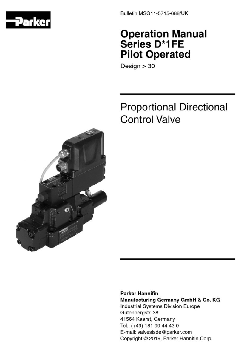
Parker D41FE User manual

Parker

Parker D41FE User manual
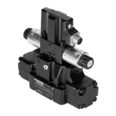
Parker PSST8M23A Installation and maintenance instructions

Parker

Parker PSST8M23A Installation and maintenance instructions

Parker DxFB Series User manual

Parker

Parker DxFB Series User manual

Parker S5A Guide

Parker

Parker S5A Guide

Parker PID00A-40 Series User manual

Parker

Parker PID00A-40 Series User manual

Parker DINCon II Assembly instructions

Parker

Parker DINCon II Assembly instructions

Popular Control Unit manuals by other brands

Pepperl+Fuchs VAA-2E-KE1-S Original instructions

Pepperl+Fuchs

Pepperl+Fuchs VAA-2E-KE1-S Original instructions

Kobelt 2544 Owner's Operation, Installation & Maintenance Manual

Kobelt

Kobelt 2544 Owner's Operation, Installation & Maintenance Manual

Ebyte E104-BT11 user manual

Ebyte

Ebyte E104-BT11 user manual

Honeywell REDLINK ERM5220R Product data

Honeywell

Honeywell REDLINK ERM5220R Product data

Duali DE-ABCM6 user manual

Duali

Duali DE-ABCM6 user manual

ENSIM SENSORS ELV Series operating manual

ENSIM SENSORS

ENSIM SENSORS ELV Series operating manual

Controlli VSBT quick start guide

Controlli

Controlli VSBT quick start guide

KEBCO F5 COMBICOM ModBus instruction manual

KEBCO

KEBCO F5 COMBICOM ModBus instruction manual

Raita BioModule Manual Installation

Raita

Raita BioModule Manual Installation

Siemens RUGGEDCOM RS900 installation guide

Siemens

Siemens RUGGEDCOM RS900 installation guide

DEHAS DEMAND VALVE QualityFlow operating instructions

DEHAS

DEHAS DEMAND VALVE QualityFlow operating instructions

Leadshine DM542 user manual

Leadshine

Leadshine DM542 user manual

Belden Lumberg Automation LioN-P 0980 ESL... manual

Belden

Belden Lumberg Automation LioN-P 0980 ESL... manual

SMART Embedded Computing RTM-ATCA-F140 Series Installation & use

SMART Embedded Computing

SMART Embedded Computing RTM-ATCA-F140 Series Installation & use

GEM R488 Victoria operating instructions

GEM

GEM R488 Victoria operating instructions

EL.MO. Spa SCMAS5 Technical manual

EL.MO. Spa

EL.MO. Spa SCMAS5 Technical manual

Texas Instruments TPS5430 user guide

Texas Instruments

Texas Instruments TPS5430 user guide

Siemens FDCI221 Installation

Siemens

Siemens FDCI221 Installation

manuals.online logo
manuals.online logoBrands
  • About & Mission
  • Contact us
  • Privacy Policy
  • Terms and Conditions

Copyright 2025 Manuals.Online. All Rights Reserved.