Studer D424 Training manual

Studer D424
2-Channel Magneto-Optical Disk Recorder,
SW Version 1.6
1. General
2. Operating Elements
3. Quick Start Guide
4. Operation
5. Troubleshooting
6. Circuit Description/Jumper Setting – D424
7. Circuit Description/Jumper Setting – Desktop Controller
8. Diagrams
9. Appendix
Operating and Service Instructions

Prepared and edited by Copyright by Studer Professional Audio AG
Studer Professional Audio AG Printed in Switzerland
Technical Documentation Order no. 10.27.3811 (Ed. 0202)
Althardstrasse 30
CH-8105 Regensdorf – Switzerland
http://www.studer.ch Subject to change
Studer is a registered trade mark of Studer Professional Audio AG, Regensdorf

SAFETY / SECURITE / SICHERHEIT
I
To reduce the risk of electric shock, do not remove covers (or back). No
user-serviceable parts inside. Refer servicing to qualified service per-
sonnel.
Afin de prévenir un choc électrique, ne pas enlever les couvercles (où
l’arrière) de l’appareil. Il ne se trouve à l’intérieur aucune pièce pouvant
être réparée par l’usager.
Um die Gefahr eines elektrischen Schlages zu vermeiden, entfernen Sie
weder Geräteabdeckungen noch Rückwand. Überlassen Sie Wartung
und Reparatur qualifiziertem Fachpersonal.
This symbol is intended to alert the user to presence of uninsulated
“dangerous voltage” within the apparatus that may be of sufficient
magnitude to constitute a risk of electric shock to a person.
Ce symbole indique à l'utilisateur qu'il existent à l'intérieur de l'appareil
des “tensions dangereuses”. Ces tensions élevées ont pour consé-
quence un risque de choc électrique en cas de contact.
Dieses Symbol deutet dem Anwender an, dass im Geräteinnern die Ge-
fahr der Berührung von “gefährlicher Spannung” besteht. Die Höhe
der Spannung kann zu einem elektrischen Schlag führen.
This symbol is intended to alert the user to the presence of important
instructions for operating and maintenance in the enclosed documenta-
tion.
Ce symbole indique à l’utilisateur que la documentation jointe contient
d'importantes instructions concernant le fonctionnement et la mainte-
nance.
Dieses Symbol deutet dem Anwender an, dass die beigelegte Doku-
mentation wichtige Hinweise für Betrieb und Wartung enthält.
CAUTION: Lithium battery. Danger of explosion by incorrect handling. Replace by
battery of the same make and type only.
ATTENTION: Pile au lithium. Danger d'explosion en cas de manipulation incorrecte.
Ne remplacer que par un modèle de même type.
ACHTUNG: Explosionsgefahr bei unsachgemässem Auswechseln der Lithium-
batterie. Nur durch den selben Typ ersetzen.
ADVARSEL: Lithiumbatterei. Eksplosinsfare. Udskinftning ma kun foretages af en
sagkyndig of som beskrevet i servicemanualen (DK).
Assemblies or sub-assemblies of this product can contain optoelectronic
devices. As long as these devices comply with Class 1 of laser or LED
product according to EN 60825-1:1994, they will not be expressly
marked on the product. If a special design should be covered by a
higher class of this standard, the device concerned will be marked di-
rectly on the assembly or sub-assembly in accordance with the above
standard.
Baugruppen oder Unterbaugruppen dieses Produktes können opto-
elektronische Komponenten enthalten. Solange diese der Klasse 1 für
Laser- oder LED-Produkte nach der Norm EN 60825-1:1994 entspre-
chen, sind sie nicht direkt am Gerät bezeichnet. Sollte eine Sonderaus-
führung in eine höhere Klasse fallen, so ist die betreffende Baugruppe
oder Unterbaugruppe gemäss dieser Norm mit entsprechender Auf-
schrift versehen.
CLASS 1
LASER PRODUCT
CLASS 1
LED PRODUCT

SAFETY / SECURITE / SICHERHEIT
II
FIRST AID
(in case of electric shock)
1. Separate the person as quickly as
possible from the electric power
source:
• by switching off the equipment
• or by unplugging or disconnecting
the mains cable
• pushing the person away from the
power source by using dry insu-
lating material (such as wood or
plastic).
•After having sustained an electric
shock, always consult a doctor.
WARNING!
DO NOT TOUCH THE PERSON
OR HIS CLOTHING BEFORE THE
POWER IS TURNED OFF, OTHER-
WISE YOU STAND THE RISK OF
SUSTAINING AN ELECTRIC
SHOCK AS WELL!
2. If the person is unconscious:
• check the pulse,
• reanimate the person if respiration
is poor,
• lay the body down, turn it to one
side, call for a doctor immediately.
PREMIERS SECOURS
(en cas d'électrocution)
1. Si la personne est dans l'impos-
sibilité de se libérer:
• Couper l'interrupteur principal
• Couper le courant
• Repousser la personne de l'appareil
à l'aide d'un objet en matière non
conductrice (matière plastique ou
bois)
•Après une électrocution, toujours
consulter un médecin.
ATTENTION!
NE JAMAIS TOUCHER UNE PER-
SONNE QUI EST SOUS TENSION,
SOUS PEINE DE SUBIR EGALE-
MENT UNE ELECTROCUTION.
2. En cas de perte de connaissance de
la personne électrocutée:
• Contrôler le pouls
• Si nécessaire, pratiquer la respi-
ration artificielle
• Placer l'accidenté sur le flanc et
consulter un médecin.
ERSTE HILFE
(bei Stromunfällen)
1. Bei einem Stromunfall die be-
troffene Person so rasch wie mög-
lich vom Strom trennen:
• Ausschalten des Gerätes
• Ziehen oder Unterbrechen der
Netzzuleitung
• Betroffene Person mit isoliertem
Material (Holz, Kunststoff) von
der Gefahrenquelle wegstossen
•Nach einem Stromunfall sollte
immer ein Arzt aufgesucht werden.
ACHTUNG!
EINE UNTER SPANNUNG STE-
HENDE PERSON DARF NICHT
BERÜHRT WERDEN. SIE KÖN-
NEN DABEI SELBST ELEKTRI-
SIERT WERDEN!
2. Bei Bewusstlosigkeit des Verun-
fallten:
• Puls kontrollieren,
• bei ausgesetzter Atmung künstlich
beatmen,
• Seitenlagerung des Verunfallten
vornehmen und Arzt verständigen.

SICHERHEIT / SAFETY
III
Installation
Vor der Installation des Gerätes müssen die hier aufgeführ-
ten und auch die weiter in dieser Anleitung mit
bezeichneten Hinweise gelesen und während der Instal-
lation und des Betriebes beachtet werden.
Untersuchen Sie das Gerät und sein Zubehör auf allfällige
Transportschäden.
Ein Gerät, das mechanische Beschädigung aufweist oder in
welches Flüssigkeit oder Gegenstände eingedrungen sind,
darf nicht ans Netz angeschlossen oder muss sofort durch
Ziehen des Netzsteckers vom Netz getrennt werden. Das
Öffnen und Instandsetzen des Gerätes darf nur von Fachper-
sonal unter Einhaltung der geltenden Vorschriften durchge-
führt werden.
Liegt dem Gerät kein konfektioniertes Netzkabel bei, so
muss dieses durch eine Fachperson unter Verwendung der
mitgelieferten Kabel-Gerätedose IEC320/C13 oder
IEC320/C19 und unter Berücksichtigung der einschlägigen,
im jeweiligen Lande geltenden Bestimmungen angefertigt
werden; siehe unten.
Vor Anschluss des Netzkabels an die Netzsteckdose muss
überprüft werden, ob die Stromversorgungs- und An-
schlusswerte des Gerätes (Netzspannung, Netzfrequenz)
innerhalb der erlaubten Toleranzen liegen. Die im Gerät
eingesetzten Sicherungen müssen den am Gerät angebrach-
ten Angaben entsprechen.
Ein Gerät mit einem dreipoligen Gerätestecker (Gerät der
Schutzklasse I) muss an eine dreipolige Netzsteckdose ange-
schlossen und somit das Gerätegehäuse mit dem Schutzleiter
der Netzinstallation verbunden werden (Für Dänemark gel-
ten Starkstrombestimmungen, Abschnitt 107).
Installation
Before you install the equipment, please read and adhere to
the following recommendations and all sections of these
instructions marked with .
Check the equipment for any transport damage.
A unit that is mechanically damaged or which has been
penetrated by liquids or foreign objects must not be con-
nected to the AC power outlet or must be immediately dis-
connected by unplugging the power cable. Repairs must only
be performed by trained personnel in accordance with the
applicable regulations.
Should the equipment be delivered without a matching mains
cable, the latter has to be prepared by a trained person using
the attached female plug (IEC320/C13 or IEC320/C19) with
respect to the applicable regulations in your country - see
diagram below.
Before connecting the equipment to the AC power outlet,
check that the local line voltage matches the equipment
rating (voltage, frequency) within the admissible tolerance.
The equipment fuses must be rated in accordance with the
specifications on the equipment.
Equipment supplied with a 3-pole appliance inlet (equipment
conforming to protection class I) must be connected to a 3-
pole AC power outlet so that the equipment cabinet is con-
nected to the protective earth conductor of the AC supply
(for Denmark the Heavy Current Regulations, Section 107,
are applicable).
Female plug (IEC320), view from contact side:
L live; brown National American Standard: Black
N neutral; blue White
PE protective earth; green and yellow green
Connecteur femelle (IEC320), vue de la face aux contacts:
L phase; brun Standard national américain: Noir
N neutre; bleu Blanc
PE terre protectrice; vert et jaune Vert
Ansicht auf Steckkontakte der Kabel-Gerätesteckdose (IEC320):
L Phase; braun USA-Standard: Schwarz
N Nulleiter; blau Weiss
PE Schutzleiter; gelb/grün grün
SICHERHEIT / SAFETY
IV
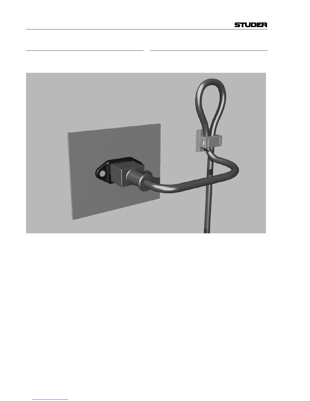
Zugentlastung für den Netzanschluss
Zum Verankern von Steckverbindungen ohne mechanische
Verriegelung (z.B. IEC-Kaltgerätedosen) empfehlen wir die
folgende Anordnung:
Vorgehen: Der mitgelieferte Kabelhalter ist selbstklebend.
Bitte beachten Sie bei der Montage die folgenden Regeln:
1. Der Untergrund muss sauber, trocken und frei von Fett,
Öl und anderen Verunreinigungen sein. Temperaturbe-
reich für optimale Verklebung: 20...40° C.
2. Entfernen Sie die Schutzfolie auf der Rückseite des Ka-
belhalters und bringen sie ihn mit kräftigem Druck an der
gewünschten Stelle an. Lassen sie ihn unbelastet so lange
wie möglich ruhen – die maximale Klebekraft ist erst
nach rund 24 Stunden erreicht.
3. Die Stabilität des Kabelhalters wird erhöht, wenn Sie ihn
zusätzlich verschrauben. Zu diesem Zweck liegen ihm
eine selbstschneidende Schraube sowie eine M4-
Schraube mit Mutter bei.
4. Legen Sie das Kabel gemäss Figur in den Halter ein und
pressen Sie die Klemme kräftig auf, bis das Kabel fixiert
ist.
Mains connector strain relief
For anchoring connectors without a mechanical lock (e.g.
IEC mains connectors), we recommend the following ar-
rangement:
Procedure: The cable clamp shipped with your unit is auto-
adhesive. If mounting, please follow the rules below:
1. The surface to be adhered to must be clean, dry, and free
from grease, oil or other contaminants. Best application
temperature range is 20...40° C.
2. Remove the plastic protective backing from the rear side
of the clamp and apply it firmly to the surface at the de-
sired position. Allow as much time as possible for curing.
The bond continues to develop for as long as 24 hours.
3. For improved stability, the clamp can be fixed with a
screw. For this purpose, a self-tapping screw and an M4
bolt and nut are included.
4. Place the cable into the clamp as shown in the illustration
above and firmly press down the internal top cover until
the cable is fixed.

UMGEBUNGSBEDINGUNGEN / AMBIENT CONDITIONS
V
Lufttemperatur und Feuchtigkeit
Allgemein
Die Betriebstauglichkeit des Gerätes oder Systems ist unter
folgenden Umgebungsbedingungen gewährleistet:
EN 60721-3-3, Set IE32, Wert 3K3.
Diese Norm besteht aus einem umfassenden Katalog von Pa-
rametern; die wichtigsten davon sind: Umgebungstemperatur
+5...+40 °C; rel. Luftfeuchtigkeit 5...85% – d.h. weder Kon-
densation noch Eisbildung; abs. Luftfeuchtigkeit 1...25 g/m³;
Temperatur-Änderungsrate < 0,5 °C/min. In den folgenden
Abschnitten wird darauf näher eingegangen.
Unter den genannten Bedingungen startet und arbeitet das
Gerät oder System problemlos. Ausserhalb dieser Spezifikatio-
nen möglicherweise auftretende Probleme sind in den folgen-
den Abschnitten beschrieben.
Umgebungstemperatur
Geräte und Systeme von Studer sind allgemein für einen Um-
gebungs-Temperaturbereich (d.h. Temperatur der eintretenden
Kühlluft) von +5...+40 °C ausgelegt. Bei Installation in einem
Schrank muss der vorgesehene Luftdurchsatz und dadurch die
Konvektionskühlung gewährleistet sein. Folgende Tatsachen
sind dabei zu berücksichtigen:
1. Die zulässige Umgebungstemperatur für den Betrieb der
Halbleiter-Bauelemente beträgt 0 °C bis +70 °C (commercial
temperature range for operation).
2. Der Luftdurchsatz der Anlage muss gewährleisten, dass die
austretende Kühlluft ständig kühler ist als 70 °C.
3. Die mittlere Erwärmung der Kühlluft soll 20 K betragen,
die maximale Erwärmung an den heissen Komponenten darf
somit um weitere 10 K höher liegen.
4. Zum Abführen einer Verlustleistung von 1 kW bei dieser
zulässigen mittleren Erwärmung ist eine Luftmenge von
2,65 m³/min notwendig.
Beispiel: Für ein Rack mit einer Leistungsaufnahme P = 800 W
ist eine Kühlluftmenge von 0,8 * 2,65 m³/min nötig, entspre-
chend 2,12 m³/min.
5. Soll die Kühlfunktion der Anlage (z.B. auch bei Lüfter-
Ausfall oder Bestrahlung durch Spotlampen) überwacht wer-
den, so ist die Temperatur der Abluft unmittelbar oberhalb der
Einschübe an mehreren Stellen im Rack zu messen; die An-
sprechtemperatur der Sensoren soll 65 bis 70 °C betragen.
Reif und Tau
Das unversiegelte System (Steckerpartien, Halbleiteranschlüs-
se) verträgt zwar leichte Eisbildung (Reif). Mit blossem Auge
sichtbare Betauung führt jedoch bereits zu Funktionsstörungen.
In der Praxis kann mit einem zuverlässigen Betrieb der Geräte
bereits im Temperaturbereich ab –15 °C gerechnet werden,
wenn für die Inbetriebnahme des kalten Systems die folgende
allgemeine Regel beachtet wird:
Wird die Luft im System abgekühlt, so steigt ihre relative
Feuchtigkeit an. Erreicht diese 100%, kommt es zu Nieder-
schlag, meist in der Grenzschicht zwischen der Luft und einer
kühleren Oberfläche, und somit zur Bildung von Eis oder Tau
an empfindlichen Systemstellen (Kontakte, IC-Anschlüsse etc.).
Ein störungsfreier Betrieb mit interner Betauung, unabhängig
von der Temperatur, ist nicht gewährleistet.
Air temperature and humidity
General
Normal operation of the unit or system is warranted under the
following ambient conditions defined by:
EN 60721-3-3, set IE32, value 3K3.
This standard consists of an extensive catalogue of parameters,
the most important of which are: ambient temperature +5...
+40° C, relative humidity 5...85% – i.e. no formation of con-
densation or ice; absolute humidity 1...25 g/m³; rate of tem-
perature change < 0,5 °C/min. These parameters are dealt with
in the following paragraphs.
Under these conditions the unit or system starts and works
without any problem. Beyond these specifications, possible
problems are described in the following sections.
Ambient temperature
Units and systems by Studer are generally designed for an
ambient temperature range (i.e. temperature of the incoming
air) of +5...+40 °C. When rack mounting the units, the intended
air flow and herewith adequate cooling must be provided. The
following facts must be considered:
1. The admissible ambient temperature range for operation of
the semiconductor components is 0 °C to +70 °C (commercial
temperature range for operation).
2. The air flow through the installation must provide that the
outgoing air is always cooler than 70 °C.
3. Average heat increase of the cooling air shall be 20 K,
allowing for an additional maximum 10 K increase at the hot
components.
4. In order to dissipate 1 kW with this admissible average heat
increase, an air flow of 2,65 m³/min is required.
Example: A rack dissipating P = 800 W requires an air flow of
0,8 * 2,65 m³/min which corresponds to 2,12 m³/min.
5. If the cooling function of the installation must be moni-
tored (e.g. for fan failure or illumination with spot lamps), the
outgoing air temperature must be measured directly above the
modules at several places within the rack. The trigger tempera-
ture of the sensors should be 65 to 70 °C.
Frost and dew
The unsealed system parts (connector areas and semiconductor
pins) allow for a minute formation of ice or frost. However,
formation of dew visible with the naked eye will already lead to
malfunctions. In practice, reliable operation can be expected in
a temperature range above –15 °C, if the following general rule
is considered for putting the cold system into operation:
If the air within the system is cooled down, the relative humid-
ity rises. If it reaches 100%, condensation will arise, usually in
the boundary layer between the air and a cooler surface, to-
gether with formation of ice or dew at sensitive areas of the
system (contacts, IC pins, etc.). Once internal condensation
occurs, trouble-free operation cannot be guaranteed, independ-
ent of temperature.
UMGEBUNGSBEDINGUNGEN / AMBIENT CONDITIONS
VI
Vor der Inbetriebnahme muss das System auf allfällige interne
Betauung oder Eisbildung überprüft werden. Nur bei sehr
leichter Eisbildung kann mit direkter Verdunstung (Sublimati-
on) gerechnet werden; andernfalls muss das System im abge-
schalteten Zustand gewärmt und getrocknet werden.
Das System ohne feststellbare interne Eisbildung oder Betau-
ung soll möglichst homogen (und somit langsam) mit eigener
Wärmeleistung aufgewärmt werden; die Lufttemperatur der
Umgebung soll ständig etwas tiefer als diejenige der Syste-
mabluft sein.
Ist es unumgänglich, das abgekühlte System sofort in warmer
Umgebungsluft zu betreiben, so muss diese entfeuchtet sein.
Die absolute Luftfeuchtigkeit muss dabei so tief sein, dass die
relative Feuchtigkeit, bezogen auf die kälteste Oberfläche im
System, immer unterhalb 100% bleibt.
Es ist dafür zu sorgen, dass beim Abschalten des Systems die
eingeschlossene Luft möglichst trocken ist (d.h. vor dem Ab-
schalten im Winter den Raum mit kalter, trockener Luft belüf-
ten und feuchte Gegenstände, z.B. Kleider, entfernen).
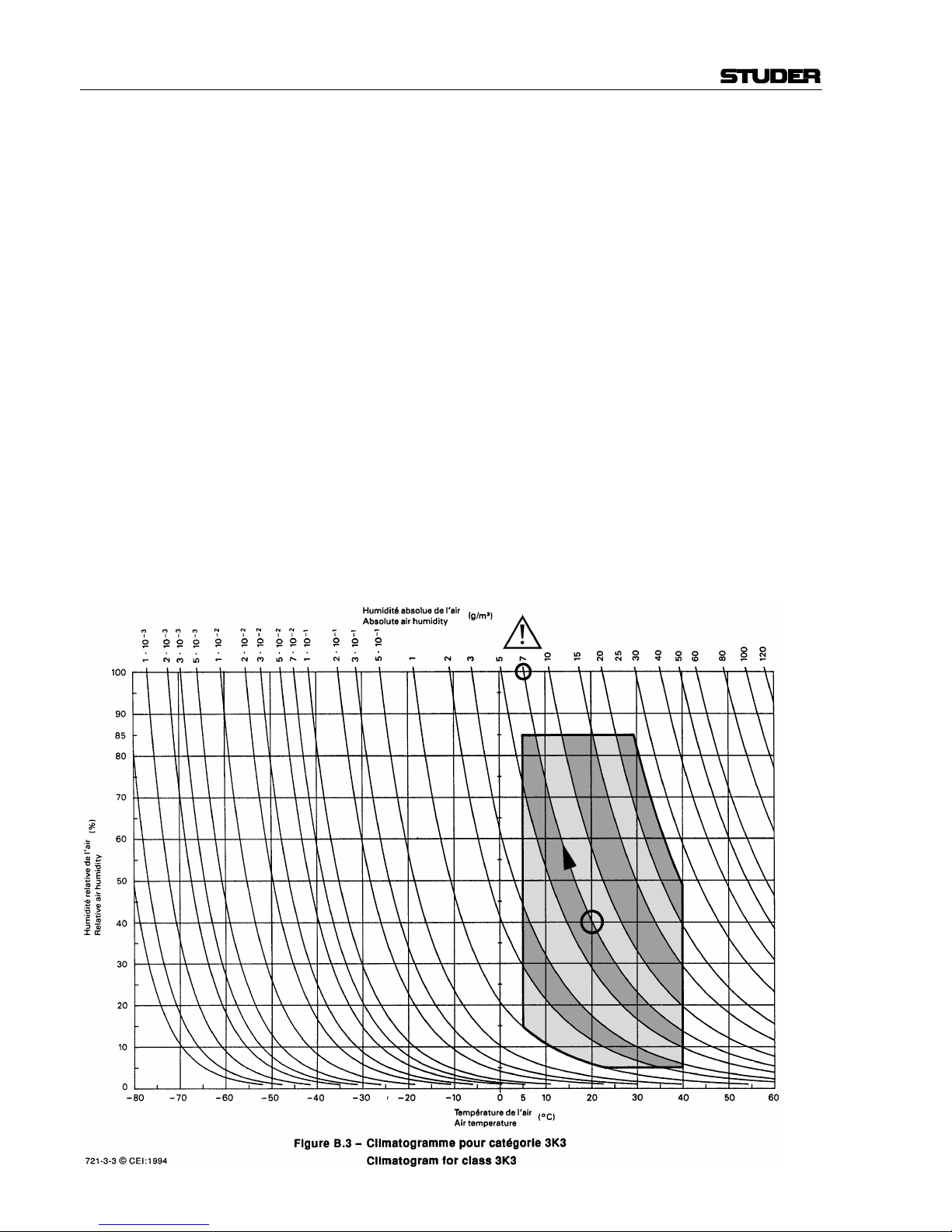
Die Zusammenhänge sind im folgenden Klimatogramm er-
sichtlich. Zum kontrollierten Verfahren gehören Thermometer
und Hygrometer sowie ein Thermometer im System.
Beispiel 1: Ein Ü-Wagen mit einer Innentemperatur von 20 °C
und 40% relativer Luftfeuchtigkeit wird am Abend abgeschal-
tet. Sinkt die Temperatur unter +5 °C, bildet sich Tau oder Eis.
Beispiel 2: Ein Ü-Wagen wird morgens mit 20 °C warmer Luft
von 40% relativer Luftfeuchtigkeit aufgewärmt. Auf Teilen, die
kälter als +5 °C sind, bildet sich Tau oder Eis.
Before putting into operation, the system must be checked for
internal formation of condensation or ice. Only with a minute
formation of ice, direct evaporation (sublimation) may be ex-
pected; otherwise the system must be heated and dried while
switched off.
A system without visible internal formation of ice or condensa-
tion should be heated up with its own heat dissipation, as ho-
mogeneously (and subsequently as slow) as possible; the ambi-
ent temperature should then always be lower than the outgoing
air.
If it is absolutely necessary to operate the system immediately
within warm ambient air, this air must be dehydrated. In such a
case, the absolute humidity must be so low that the relative
humidity, related to the coldest system surface, always remains
below 100%.
Ensure that the enclosed air is as dry as possible when power-
ing off (i.e. before switching off in winter, aerate the room with
cold, dry air, and remove humid objects as clothes from the
room).
These relationships are visible from the following climatogram.
For a controlled procedure, thermometer and hygrometer as
well as a thermometer within the system will be required.
Example 1: An OB-van having an internal temperature of
20 °C and rel. humidity of 40% is switched off in the evening.
If temperature falls below +5 °C, dew or ice will be forming.
Example 2: An OB-van is heated up in the morning with air of
20 °C and a rel. humidity of 40%. On all parts being cooler
than +5 °C, dew or ice will be forming.

WARTUNG / MAINTENANCE
VII
Wartung und Reparatur
Durch Entfernen von Gehäuseteilen, Abschirmungen etc.
werden stromführende Teile freigelegt. Deshalb müssen u.a.
die folgenden Grundsätze beachtet werden:
Eingriffe in das Gerät dürfen nur von Fachpersonal unter
Einhaltung der geltenden Vorschriften vorgenommen wer-
den.
Vor Entfernen von Gehäuseteilen muss das Gerät ausge-
schaltet und vom Netz getrennt werden.
Bei geöffnetem, vom Netz getrenntem Gerät dürfen Teile
mit gefährlichen Ladungen (z. B. Kondensatoren, Bildröh-
ren) erst nach kontrollierter Entladung, heisse Bauteile (Lei-
stungshalbleiter, Kühlkörper etc.) erst nach deren Abkühlen
berührt werden.
Bei Wartungsarbeiten am geöffneten, unter Netzspannung
stehenden Gerät dürfen blanke Schaltungsteile und metallene
Halbleitergehäuse weder direkt noch mit nichtisoliertem
Werkzeug berührt werden.
Zusätzliche Gefahren bestehen bei unsachgemässer Handha-
bung besonderer Komponenten:
•Explosionsgefahr bei Lithiumzellen, Elektrolyt-Konden-
satoren und Leistungshalbleitern
•Implosionsgefahr bei evakuierten Anzeigeeinheiten
•Strahlungsgefahr bei Lasereinheiten (nichtionisierend),
Bildröhren (ionisierend)
•Verätzungsgefahr bei Anzeigeeinheiten (LCD) und Kom-
ponenten mit flüssigem Elektrolyt.
Solche Komponenten dürfen nur von ausgebildetem Fach-
personal mit den vorgeschriebenen Schutzmitteln (u.a.
Schutzbrille, Handschuhe) gehandhabt werden.
Maintenance and Repair
The removal of housing parts, shields, etc. exposes ener-
gized parts. For this reason the following precautions should
be observed:
Maintenance should only be performed by trained personnel
in accordance with the applicable regulations.
The equipment should be switched off and disconnected
from the AC power outlet before any housing parts are re-
moved.
Even if the equipment is disconnected from the power, parts
with hazardous charges (e.g. capacitors, picture tubes) must
not be touched until they have been properly discharged.
Touch hot components (power semiconductors, heat sinks,
etc.) only when cooled off.
If maintenance is performed on a unit that is opened and
switched on, no uninsulated circuit components and metallic
semiconductor housings must be touched neither with your
bare hands nor with uninsulated tools.
Certain components pose additional hazards:
•Explosion hazard from lithium batteries, electrolytic
capacitors and power semiconductors
•Implosion hazard from evacuated display units
•Radiation hazard from laser units (non-ionizing), picture
tubes (ionizing)
•Caustic effect of display units (LCD) and such compo-
nents containing liquid electrolyte.
Such components should only be handled by trained per-
sonnel who are properly protected (e.g. safety goggles,
gloves).

WARTUNG / MAINTENANCE
VIII
Elektrostatische Entladung (ESD)
bei Wartung und Reparatur
ATTENTION:
ATTENTION:
ACHTUNG:
Viele ICs und andere Halbleiter sind empfindlich gegen
elektrostatische Entladung (ESD). Unsachgemässe Behand-
lung von Baugruppen mit solchen Komponenten bei War-
tung und Reparatur kann deren Lebensdauer drastisch ver-
mindern.
Bei der Handhabung der ESD-empfindlichen Komponenten
sind u.a. folgende Regeln zu beachten:
• ESD-empfindliche Komponenten dürfen ausschliesslich
in dafür bestimmten und bezeichneten Verpackungen ge-
lagert und transportiert werden.
• Unverpackte, ESD-empfindliche Komponenten dürfen
nur in dafür eingerichteten Schutzzonen (EPA, z.B. Ge-
biet für Feldservice, Reparatur- oder Serviceplatz) ge-
handhabt und nur von Personen berührt werden, die durch
ein Handgelenkband mit Serienwiderstand mit dem Mas-
sepotential des Reparatur- oder Serviceplatzes verbunden
sind. Das gewartete Gerät wie auch Werkzeug, Hilfsmit-
tel, EPA-taugliche (elektrisch halbleitende) Arbeits-, Ab-
lage- und Bodenmatten müssen ebenfalls mit diesem Po-
tential verbunden sein.
• Die Anschlüsse der ESD-empfindlichen Komponenten
dürfen unkontrolliert weder mit elektrostatisch aufladba-
ren (Gefahr von Spannungsdurchschlag), noch mit metal-
lischen Oberflächen (Schockentladungsgefahr) in Berüh-
rung kommen.
• Um undefinierte transiente Beanspruchung der Kompo-
nenten und deren eventuelle Beschädigung durch un-
erlaubte Spannung oder Ausgleichsströme zu vermeiden,
dürfen elektrische Verbindungen nur am abgeschalteten
Gerät und nach dem Abbau allfälliger Kondensator-
ladungen hergestellt oder getrennt werden.
Electrostatic Discharge (ESD)
during Maintenance and Repair
Observe precautions for handling devices sensitive to elec-
trostatic discharge!
Respecter les précautions d’usage concernant la mani-
pulation de composants sensibles à l’électricité statique!
Vorsichtsmassnahmen bei der Handhabung von ESD-
empfindlichen Bauelementen beachten!
Many ICs and semiconductors are sensitive to electrostatic
discharge (ESD). The life of components containing such
elements can be drastically reduced by improper handling
during maintenance and repair work.
Please observe the following rules when handling ESD sen-
sitive components:
• ESD sensitive components should only be stored and
transported in the packing material specifically provided
for this purpose.
• Unpacked ESD sensitive components should only be
handled in ESD protected areas (EPA, e.g. area for field
service, repair or service bench) and only be touched by
persons who wear a wristlet that is connected to the
ground potential of the repair or service bench by a series
resistor. The equipment to be repaired or serviced and all
tools, aids, as well as electrically semi-conducting work,
storage and floor mats should also be connected to this
ground potential.
• The terminals of ESD sensitive components must not
come in uncontrolled contact with electrostatically
chargeable (voltage puncture) or metallic surfaces (dis-
charge shock hazard).
• To prevent undefined transient stress of the components
and possible damage due to inadmissible voltages or
compensation currents, electrical connections should only
be established or separated when the equipment is
switched off and after any capacitor charges have de-
cayed.
WARTUNG / MAINTENANCE
IX
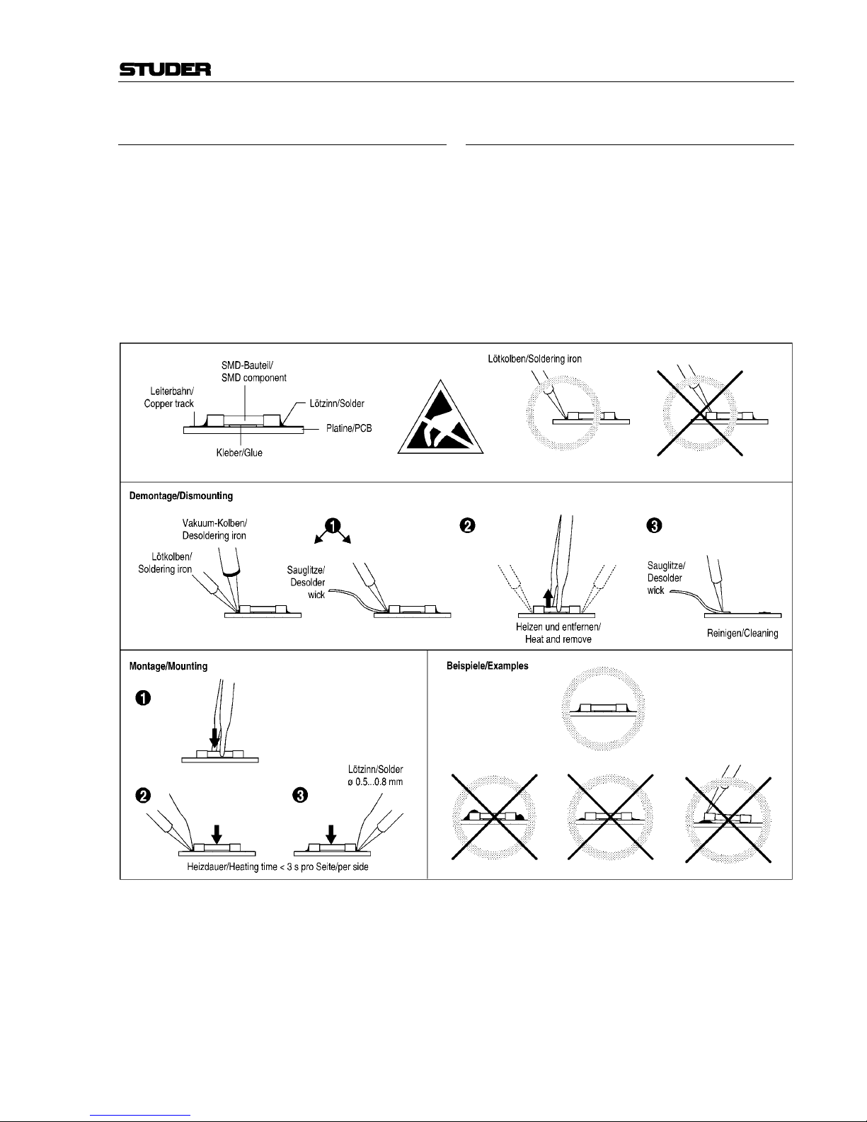
SMD-Bauelemente
Der Austausch von SMD-Bauelementen ist ausschliesslich
geübten Fachleuten vorbehalten. Für verwüstete Platinen
können keine Ersatzansprüche geltend gemacht werden.
Beispiele für korrekte und falsche SMD-Lötverbindungen in
der Abbildung weiter unten.
Bei Studer werden keine handelsüblichen SMD-Bauteile
bewirtschaftet. Für Reparaturen sind die notwendigen Bau-
teile lokal zu beschaffen. Die Spezifikationen von Spezialb-
auteilen finden Sie in der Serviceanleitung.
SMD Components
SMD components should only be replaced by skilled spe-
cialists. No warranty claims will be accepted for circuit
boards that have been ruined. Proper and improper SMD
soldering joints are depicted below.
Studer does not keep any commercially available SMD
components in stock. For repair the corresponding devices
should be purchased locally. The specifications of special
components can be found in the service manual.

EMV / EMC
X
Störstrahlung und Störfestigkeit
Das Gerät entspricht den Schutzanforderungen auf dem
Gebiet elektromagnetischer Phänomene, wie u.a. in den
Richtlinien 89/336/EWG und FCC, Part 15, aufgeführt:
1. Vom Gerät erzeugte elektromagnetische Strahlung ist
soweit begrenzt, dass bestimmungsgemässer Betrieb an-
derer Geräte und Systeme möglich ist.
2. Das Gerät weist eine angemessene Festigkeit gegen elek-
tromagnetische Störungen auf, so dass sein bestimmungs-
gemässer Betrieb möglich ist.
Das Gerät wurde getestet und erfüllt die Bedingungen der im
Kapitel „Technische Daten“ aufgeführten EMV-Normen.
Die Limiten dieser Standards gewährleisten mit angemesse-
ner Wahrscheinlichkeit sowohl den Schutz der Umgebung
wie auch entsprechende Störfestigkeit des Gerätes. Absolute
Garantie, dass keine unerlaubte elektromagnetische Beein-
trächtigung während des Betriebes entsteht, ist jedoch nicht
gegeben.
Um die Wahrscheinlichkeit solcher Beeinträchtigung weit-
gehend auszuschliessen, sind u.a. folgende Massnahmen zu
beachten:
• Installieren Sie das Gerät gemäss den Angaben in der Be-
triebsanleitung, und verwenden Sie das mitgelieferte Zu-
behör.
• Verwenden Sie im System und in der Umgebung, in de-
nen das Gerät eingesetzt ist, nur Komponenten (Anlagen,
Geräte), die ihrerseits die Anforderungen der obener-
wähnten Standards erfüllen.
• Sehen Sie ein Erdungskonzept des Systems vor, das so-
wohl die Sicherheitsanforderungen (die Erdung der Ge-
räte gemäss Schutzklasse I mit einem Schutzleiter muss
gewährleistet sein), wie auch die EMV-Belange berück-
sichtigt. Bei der Entscheidung zwischen stern- oder flä-
chenförmiger bzw. kombinierter Erdung sind Vor- und
Nachteile gegeneinander abzuwägen.
• Benutzen Sie abgeschirmte Kabel, wo vorgesehen. Ach-
ten Sie auf einwandfreie, grossflächige, korrosions-
beständige Verbindung der Abschirmung zum entspre-
chenden Steckeranschluss und dessen Gehäuse. Beachten
Sie, dass eine nur an einem Ende angeschlossene Ka-
belabschirmung als Sende- bzw. Empfangsantenne wirken
kann (z.B. bei wirksamer Kabellänge von 5 m oberhalb
von 10 MHz), und dass die Flanken digitaler Kommuni-
kationssignale hochfrequente Aussendungen verursachen
(z.B. LS- oder HC-Logik bis 30 MHz).
• Vermeiden Sie Bildung von Masseschleifen oder ver-
mindern Sie deren unerwünschte Auswirkung, indem Sie
deren Fläche möglichst klein halten und den darin flie-
ssenden Strom durch Einfügen einer Impedanz (z.B.
Gleichtaktdrossel) reduzieren.
Electromagnetic Compatibility
The equipment conforms to the protection requirements
relevant to electromagnetic phenomena that are listed in the
guidelines 89/336/EC and FCC, part 15.
1. The electromagnetic interference generated by the equip-
ment is limited in such a way that other equipment and
systems can be operated normally.
2. The equipment is adequately protected against electro-
magnetic interference so that it can operate correctly.
The unit has been tested and conforms to the EMC standards
applicable to residential, commercial and light industry, as
listed in the section „Technical Data“. The limits of these
standards reasonably ensure protection of the environment
and corresponding noise immunity of the equipment. How-
ever, it is not absolutely warranted that the equipment will
not be adversely affected by electromagnetic interference
during operation.
To minimize the probability of electromagnetic interference
as far as possible, the following recommendations should be
followed:
• Install the equipment in accordance with the operating
instructions. Use the supplied accessories.
• In the system and in the vicinity where the equipment is
installed, use only components (systems, equipment) that
also fulfill the above EMC standards.
• Use a system grounding concept that satisfies the safety
requirements (protection class I equipment must be con-
nected with a protective ground conductor) that also takes
into consideration the EMC requirements. When deciding
between radial, surface or combined grounding, the ad-
vantages and disadvantages should be carefully evaluated
in each case.
• Use shielded cables where shielding is specified. The
connection of the shield to the corresponding connector
terminal or housing should have a large surface and be
corrosion-proof. Please note that a cable shield connected
only single-ended can act as a transmitting or receiving
antenna (e.g. with an effective cable length of 5 m, the
frequency is above 10 MHz) and that the edges of the
digital communication signals cause high-frequency ra-
diation (e.g. LS or HC logic up to 30 MHz).
• Avoid ground loops or reduce their adverse effects by
keeping the loop surface as small as possible, and reduce
the noise current flowing through the loop by inserting an
additional impedance (e.g. common-mode rejection
choke).

Konformitätserklärungen / Declarations of conformity
XI
Class A Equipment - FCC Notice
This equipment has been tested and found to comply with
the limits for a Class A digital device, pursuant to Part 15 of
the FCC Rules. These limits are designed to provide a rea-
sonable protection against harmful interference when the
equipment is operated in a commercial environment. This
equipment generates, uses, and can radiate radio frequency
energy and, if not installed and used in accordance with the
instruction manual, may cause harmful interference to radio
communications. Operation of this equipment in a residential
area is likely to cause harmful interference in which case the
user will be required to correct the interference at his own
expense.
Caution:
Any changes or modifications not expressly approved by the
manufacturer could void the user's authority to operate the
equipment. Also refer to relevant information in this man-
ual.
CE-Konformitätserklärung
Der Hersteller,
Studer Professional Audio AG,
CH-8105 Regensdorf,
erklärt in eigener Verantwortung, dass das Produkt
Studer D424, 2-Channel Professional MO-Disk Recorder,
(ab Serie-Nr. 101),
auf das sich diese Erklärung bezieht, entsprechend den Be-
stimmungen der EU-Richtlinien und Ergänzungen
• Elektromagnetische Verträglichkeit (EMV):
89/336/EWG + 92/31/EWG + 93/68/EWG
• Niederspannung:
73/23/EWG + 93/68/EWG
mit den folgenden Normen und normativen Dokumenten
übereinstimmt:
• Sicherheit:
Schutzklasse 1, EN 60950:1992 + A1/A2:1993
•EMV:
EN 50081-1:1992, EN 50082-1:1992
Regensdorf, 18. Juli 1996
B. Hochstrasser, President, International Sales
P. Fiala, Leiter QS
CE Declaration of Conformity
The manufacturer,
Studer Professional Audio AG,
CH-8105 Regensdorf,
declares under his sole responsibility that the product
Studer D424, 2-Channel Professional MO-Disk Recorder,
(on from serial No. 101),
to which this declaration relates, according to following
regulations of EU directives and amendments
• Electromagnetic Compatibility (EMC):
89/336/EEC + 92/31/EEC + 93/68/EEC
• Low Voltage (LVD):
73/23/EEC + 93/68/EEC
is in conformity with the following standards or other nor-
mative documents:
• Safety:
Class 1, EN 60950:1992 + A1/A2:1993
•EMC:
EN 50081-1:1992, EN 50082-1:1992
Regensdorf, July 18, 1996
B. Hochstrasser, President, International Sales
P. Fiala, Manager QA

D424 MO Recorder
Date printed: 06.03.02 SW V 1.6 Contents E0/1
CONTENTS
1 General......................................................................................................................................................................... E1/1
1.1 MO Recording................................................................................................................................................... E1/1
1.2 The Medium – Magneto-Optical Disks.............................................................................................................. E1/2
1.2.1 Disk Standards................................................................................................................................................E1/2
1.2.2 Disk Formatting..............................................................................................................................................E1/3
1.2.3 Disk Capacities...............................................................................................................................................E1/3
1.2.4 Disk Handling.................................................................................................................................................E1/4
1.3 File Systems, File Formats, Audio Files ............................................................................................................ E1/5
1.3.1 Takes, Indices, and Sequences........................................................................................................................E1/5
1.3.2 Non-Destructive Editing.................................................................................................................................E1/7
1.4 Utilization for the Purpose Intended.................................................................................................................. E1/8
1.5 Copyright........................................................................................................................................................... E1/8
1.6 First Steps.......................................................................................................................................................... E1/8
1.6.1 Unpacking and Inspection ..............................................................................................................................E1/8
1.6.2 Installation......................................................................................................................................................E1/8
1.6.3 Adjustments, Repair........................................................................................................................................E1/9
1.6.4 Accessories, Options.......................................................................................................................................E1/9
1.6.5 Connector Field ............................................................................................................................................E1/10
1.6.6 Connector Pin Assignments..........................................................................................................................E1/11
1.7 Technical Specifications.................................................................................................................................. E1/13
1.7.1 Drive System ................................................................................................................................................E1/13
1.7.2 Recording Formats........................................................................................................................................E1/13
1.7.3 Audio Processing..........................................................................................................................................E1/13
1.7.4 Audio Input/ Output......................................................................................................................................E1/13
1.7.5 Synchronization............................................................................................................................................E1/14
1.7.6 Timecode......................................................................................................................................................E1/14
1.7.7 Control Interfaces .........................................................................................................................................E1/14
1.7.8 Power Supply................................................................................................................................................E1/15
1.7.9 Operating Conditions....................................................................................................................................E1/15
1.7.10 Standards ......................................................................................................................................................E1/15
1.7.11 Physical Dimensions.....................................................................................................................................E1/15
1.8 Syntax Used in this Manual............................................................................................................................. E1/16
2 Operating elements..................................................................................................................................................... E2/1
2.1 General............................................................................................................................................................... E2/2
2.2 Transport Section............................................................................................................................................... E2/2
2.3 Editing Section................................................................................................................................................... E2/3
2.4 Keyboard and Register Section.......................................................................................................................... E2/3
2.5 Display and Menu Section................................................................................................................................. E2/4
2.6 Additional Functions (Desktop Controller only)................................................................................................ E2/4

D424 MO Recorder
E0/2 Contents SW V 1.6 Date printed: 06.03.02
3 Getting Started Quickly..............................................................................................................................................E3/1
3.1 Recording New Takes From an Analog Source .................................................................................................E3/1
3.1.1 Installation and Settings ................................................................................................................................. E3/1
3.1.2 Start Recording............................................................................................................................................... E3/1
3.2 Recording New Takes From a Digital Source....................................................................................................E3/2
3.2.1 Installation and Settings ................................................................................................................................. E3/2
3.2.2 Start Recording............................................................................................................................................... E3/2
3.3 Playing Pre-Recorded Disks...............................................................................................................................E3/3
3.3.1 Installation and Settings ................................................................................................................................. E3/3
3.3.2 Position .......................................................................................................................................................... E3/3
3.3.3 PLAY and STOP............................................................................................................................................ E3/3
3.3.4 Skip to Take and Index Markers .................................................................................................................... E3/3
3.3.5 CUE and SHUTTLE ...................................................................................................................................... E3/3
3.3.6 LOCATE........................................................................................................................................................ E3/4
3.3.7 Setting Markers.............................................................................................................................................. E3/4
3.4 Editing................................................................................................................................................................E3/5
3.4.1 Before You Start Editing................................................................................................................................ E3/5
3.4.2 Cut Out or Erase an Element – Cut/ Erase Editing......................................................................................... E3/5
3.4.3 Move or Duplicate an Element – Insert Editing............................................................................................. E3/6
3.5 Insert Recording.................................................................................................................................................E3/7
3.5.1 Before You Start Recording........................................................................................................................... E3/7
3.5.2 Manual Insert Recording................................................................................................................................ E3/7
3.5.3 Auto Insert Recording.................................................................................................................................... E3/7
3.6 Working with Sequences....................................................................................................................................E3/8
3.6.1 Change the Current Sequence ........................................................................................................................ E3/8
3.6.2 Create a New Sequence.................................................................................................................................. E3/8
3.6.3 Modify a Sequence......................................................................................................................................... E3/8
3.6.4 Copy a Sequence............................................................................................................................................ E3/9
3.6.5 Delete a Sequence.......................................................................................................................................... E3/9
3.7 CD Transfer and Disk Copies...........................................................................................................................E3/10
3.7.1 Before you Start the Transfer....................................................................................................................... E3/10
3.7.2 Creating a CD with an External SCSI CD Writer (e.g. Studer D741).......................................................... E3/10
3.7.3 Copying a CD to the D424........................................................................................................................... E3/11
3.7.4 Copying to/ from Other MO Disks............................................................................................................... E3/11
3.8 Working with Timecode...................................................................................................................................E3/12
3.8.1 Recording Timecode.................................................................................................................................... E3/12
3.8.2 Playing Back Timecode ............................................................................................................................... E3/12
3.8.3 Chasing to Timecode.................................................................................................................................... E3/12
3.9 The Desktop Controller....................................................................................................................................E3/13
3.9.1 Installation and Settings ............................................................................................................................... E3/13
3.9.2 Operation Enhancements.............................................................................................................................. E3/13
3.10 The Parallel Port with Fader Start Operation...................................................................................................E3/14
3.10.1 Signal List .................................................................................................................................................... E3/14
3.10.2 Fader Start.................................................................................................................................................... E3/14
3.11 The Setup Menu...............................................................................................................................................E3/15

D424 MO Recorder
Date printed: 06.03.02 SW V 1.6 Contents E0/3
4 Operation..................................................................................................................................................................... E4/1
4.1 System Configuration ........................................................................................................................................ E4/1
4.1.1 Recording Formats..........................................................................................................................................E4/1
4.1.2 Audio Input.....................................................................................................................................................E4/2
4.1.3 Reference Clock Source..................................................................................................................................E4/2
4.1.4 Other Parameters ............................................................................................................................................E4/3
4.2 Display and Register Functions ......................................................................................................................... E4/4
4.2.1 Display Information and Formats ...................................................................................................................E4/4
4.2.2 Using General Purpose Registers....................................................................................................................E4/6
4.3 Basic Transport Operation................................................................................................................................. E4/7
4.3.1 The Current Position.......................................................................................................................................E4/7
4.3.2 Playback and Stop ..........................................................................................................................................E4/9
4.3.3 Skipping to Take and Index Markers..............................................................................................................E4/9
4.3.4 The CUE and SHUTTLE Modes....................................................................................................................E4/9
4.3.5 Locating to a Random Position.....................................................................................................................E4/10
4.4 Recording......................................................................................................................................................... E4/11
4.4.1 The D424 Recording Modes.........................................................................................................................E4/11
4.4.2 Channel Assignments....................................................................................................................................E4/12
4.4.3 Rehearse Mode.............................................................................................................................................E4/12
4.4.4 Meters...........................................................................................................................................................E4/13
4.4.5 Adjusting the Analog Input Level.................................................................................................................E4/13
4.4.6 Before You Start Recording... ......................................................................................................................E4/13
4.4.7 Assemble Recording.....................................................................................................................................E4/14
4.4.8 Insert Recording ...........................................................................................................................................E4/14
4.4.9 Auto Insert Recording...................................................................................................................................E4/15
4.5 Editing ............................................................................................................................................................. E4/16
4.5.1 Setting IN and OUT Points...........................................................................................................................E4/16
4.5.2 The CUT Function........................................................................................................................................E4/17
4.5.3 The ERASE Function ...................................................................................................................................E4/18
4.5.4 The INSERT Function..................................................................................................................................E4/18
4.5.5 Combined Editing Processes ........................................................................................................................E4/19
4.5.6 The PREVIEW Function..............................................................................................................................E4/19
4.6 Sequence Editing ............................................................................................................................................. E4/21
4.6.1 Selecting a Sequence ....................................................................................................................................E4/21
4.6.2 Creating a New Sequence.............................................................................................................................E4/21
4.6.3 Deleting a Sequence .....................................................................................................................................E4/21
4.6.4 Editing a Sequence .......................................................................................................................................E4/22
4.7 CD Transfer and Disk Copies.......................................................................................................................... E4/24
4.7.1 Configuration................................................................................................................................................E4/24
4.7.2 Transfer to a CD Writer................................................................................................................................E4/24
4.7.3 Copying a CD to the D424 ...........................................................................................................................E4/26
4.7.4 Copying to/from Other Disks........................................................................................................................E4/27
4.7.5 Transfer Parameters......................................................................................................................................E4/28
4.7.6 SCSI Addresses ............................................................................................................................................E4/29
4.8 Backup Copies................................................................................................................................................. E4/30
4.8.1 Sequence Backup..........................................................................................................................................E4/30
4.8.2 Disk Backup .................................................................................................................................................E4/31
4.9 Data Exchange with SADiE®Workstations..................................................................................................... E4/32
4.9.1 DAW Configuration .....................................................................................................................................E4/32
4.9.2 Importing D424 Disks to the DAW..............................................................................................................E4/32
4.9.3 Importing SADiE®Disks to the D424..........................................................................................................E4/33

D424 MO Recorder
E0/4 Contents SW V 1.6 Date printed: 06.03.02
4.10 Setup Menu ......................................................................................................................................................E4/34
4.10.1 Accessing and Modifying Menu Items......................................................................................................... E4/34
4.10.2 Overview...................................................................................................................................................... E4/35
4.10.3 Menu 1, CONFIG (System Configuration) .................................................................................................. E4/36
4.10.4 Menu 2, REF & INP (Reference & Input Parameters)................................................................................. E4/37
4.10.5 Menu 3, AUDIO (Audio Parameters) .......................................................................................................... E4/38
4.10.6 Menu 4, TRANSPORT (Transport & Display Parameters)......................................................................... E4/39
4.10.7 Menu 5, DISK (Disk & Sequence Utilities)................................................................................................. E4/40
4.10.8 Menu 6, COPY (Copy Utilities)................................................................................................................... E4/42
4.10.9 Menu 7, SERVICE (Service Utilities).......................................................................................................... E4/44
4.11 Desktop Controller...........................................................................................................................................E4/45
4.11.1 Configuration ............................................................................................................................................... E4/45
4.11.2 Operation...................................................................................................................................................... E4/45
4.12 Parallel Port and Fader Start Operation............................................................................................................E4/46
4.12.1 Specifications............................................................................................................................................... E4/46
4.12.2 Signal Description........................................................................................................................................ E4/46
4.12.3 Fader Start.................................................................................................................................................... E4/47
4.13 Serial Remote Operation..................................................................................................................................E4/48
4.13.1 Command List.............................................................................................................................................. E4/48
5 Troubleshooting...........................................................................................................................................................E5/1
5.1 Error Messages...................................................................................................................................................E5/1
5.2 Modifying the D424 SCSI Address....................................................................................................................E5/3
6 D424 - Circuits, Jumper Setting.................................................................................................................................E6/1
6.1 Motherboard.......................................................................................................................................................E6/1
6.1.1 Clock Regeneration........................................................................................................................................ E6/1
6.1.2 Time Code...................................................................................................................................................... E6/2
6.1.3 Audio.............................................................................................................................................................. E6/2
6.1.4 Desktop Controller......................................................................................................................................... E6/3
6.1.5 Power Supply................................................................................................................................................. E6/3
6.1.6 Jumper and DIP Switch Settings.................................................................................................................... E6/3
6.2 Core....................................................................................................................................................................E6/4
6.2.1 Jumper and DIP Switch Settings.................................................................................................................... E6/4
6.3 A/D-D/A Board..................................................................................................................................................E6/5
6.3.1 Level Setting ................................................................................................................................................. E6/5
6.4 Keyboard ...........................................................................................................................................................E6/5
6.5 Display Board ....................................................................................................................................................E6/5
6.6 Connector Pin Assignments ...............................................................................................................................E6/6
7 Desktop Controller - Circuits, Jumper Setting.........................................................................................................E7/1
7.1 Remote Keyboard ..............................................................................................................................................E7/1
7.2 Remote Control PCB .........................................................................................................................................E7/1
7.3 Display PCB ......................................................................................................................................................E7/1

D424 MO Recorder
Date printed: 06.03.02 SW V 1.6 Contents E0/5
8 Diagrams..............................................................................................................................................................................
9 Appendix...................................................................................................................................................................... E9/1
9.1 Serial Remote Protocol...................................................................................................................................... E9/1
9.1.1 RS422 9-pin Protocol (Sony-Compatible)......................................................................................................E9/1
9.1.2 Communication Format ..................................................................................................................................E9/1
9.1.3 Hardware Layer ..............................................................................................................................................E9/2
9.1.4 Messages.........................................................................................................................................................E9/2
9.1.5 Command List.................................................................................................................................................E9/4
9.1.6 Command Messages .......................................................................................................................................E9/5
9.2 Drive Installation Instructions............................................................................................................................ E9/7
9.2.1 MO Drive Kit 2.6 GB (ISO)...........................................................................................................................E9/7
9.2.2 MO Drive Kit 5.2 GB (ISO)...........................................................................................................................E9/8
9.3 Hardware Configuration (Jumper and DIP Switch Settings) ............................................................................. E9/9
9.3.1 Motherboard...................................................................................................................................................E9/9
9.3.2 Core................................................................................................................................................................E9/9

D424 MO Recorder
Date printed: 22.02.02 SW V 1.6 General E1/1
1GENERAL
1.1 MO Recording
For a long time, analog tape recording has been the standard recording
technology in the professional audio industry. The step into the digital
audio era has been done a few years ago with the introduction of digital
tape recorders, such as DASH and R-DAT machines. Another important
evolution was pushed by the computer industry: Hard disk-based worksta-
tions record on fast, direct-access media that are also capable for later ed-
iting without destroying the original information.
Beginning with the consumer format CD, a removable medium with ex-
cellent price and archiving characteristics, the optical disk became in the
meantime a reliable recording media standard, in audio and computer in-
dustry.
Taking the advantages of the above approaches:
• Well accepted and easy-to-understand surface of a dedicated audio re-
corder,
• Versatile and future-proof technology, based on standard data storage de-
vices (SCSI-2),
• Removable medium with very good archiving characteristics and the capa-
bility for direct access editing,
the Studer D424-2 MO recorder has been designed to be integrated into
today's and future environments, combined with analog and digital audio
processing and automation. It is ready to follow the rapid evolution of re-
cording technology, without neglecting the needs of the professional user.
D424 MO Recorder
E1/2 General SW V 1.6 Date printed: 22.02.02
1.2 The Medium – Magneto-Optical Disks
1.2.1 Disk Standards
The D424 MO recorder with ISO drive is equipped with a 5.25" MO drive
capable of reading and writing to the standard double-sided 5.25" disk
types listed below. Only high-quality disks should be used for the D424
application. Please contact your Studer representative for information on
the recommended suppliers.
1.2 GB (512 bytes/sector) available on request
2.3 GB (512 bytes/sector) available on request
1.3 GB (1024 bytes/sector) available on request
2.6 GB (1024 bytes/sector) Order No. 15.622.260.13
4.8 GB (1024 bytes/sector) available on request
5.2 GB (2048 bytes/sector) available on request
The D424 will automatically recognize the type of the disk being inserted.
Direct-overwrite (LIM-DOW) type disks are only supported when the
D424 is equipped with a F-541-DW drive.
1.2.2 Disk Formatting
New disks are preformatted from the manufacturer. This process is called
“low-level formatting”. It is only useful after having cleaned a disk that
had numerous defective blocks. Low-level formatting will then re-check
every bit on the disk for validity, which can take up to 40 minutes.
In order to start recording, the D424 only has to add the basic system files.
Building up a DOS system and installing the basic D424 files is called
“high-level formatting”, or simply “formatting”. This process takes only a
few seconds.
After inserting a new, empty disk for the first time, the D424 will auto-
matically ask for formatting. Any prerecorded disk may be re-formatted at
any time. This is a fast and direct way to delete the whole contents of a
disk.
Table of contents
Other Studer Recording Equipment manuals

Studer
Studer Vista User manual

Studer
Studer D19 MasterSync User manual

Studer
Studer DAD-16 Troubleshooting guide

Studer
Studer A807 User manual

Studer
Studer OnAir 2500 User manual

Studer
Studer A810 Training manual

Studer
Studer V-Eight User manual

Studer
Studer PR99 MKIII User manual

Studer
Studer J37 User manual

Studer
Studer D21m User manual


