Studio Designs F12A0004CP User manual

ITEM / ARTÍCULO #100840446 / 100840438
MODEL / MODELO #F12A0004CP / F12A0004NP
dd
P
i
p
e
J
o
i
n
t
C
o
m
p
o
u
n
Installation Checklist
(Installation items sold separately)
Lista de vericación de instalación
(Artículos para la instalación vendidos por separado)
Screwdriver
Destornillador
Plumber’s tape
Cinta de plomero
Measuring tape
Cinta métrica
Thermometer
Termómetro
Safety goggles
Gafas de seguridad
Pipe joint compound
Compuesto para uniones de
tuberías
Need Help? Please call our toll-free Technical Support line at 1-888-328-2383 for additional assistance or missing parts.
¿Necesitas ayuda? Favor de llamar a nuestro servicio de soporte técnico sin costo al 1-888-328-2383 para asistencia
adicional o piezas faltantes.
Adjustable wrench
Llave ajustable
Rhiver
Tub & Shower Faucet
Grifo para bañera y ducha
Safety Tips
• Caution: If you use soldering for the installation of this faucet,
the seat, cartridges and washers will have to be removed before
turning on the flame. Damage to the cartridge and seats will
occur if left intact while soldering and will result in the warranty
being void on these parts.
• Cover your drain to avoid losing parts.
• The fittings should be installed by a licensed plumber.
Consejos de seguridad
• Advertencia: Si usa soldadura para la instalación de este grifo,
remueva los componentes internos y las arandelas antes de
encender la llama. Si no se remueven, estas piezas se dañarán
durante la soldadura, lo que resultará en la anulación de la
garantía para estas piezas.
• Cubre el drenaje para evitar que se pierdan piezas.
• Estos acoplamientos deben ser instalados por un plomero con
licencia.

2
Safety information
Please read and understand this entire manual before attempting to assemble, operate or install the
product.
NOISE AND WATER HAMMER IN PEX SYSTEMS
As with all plumbing materials under some operating conditions, water hammer can occur in PEX
plumbing systems. The inherent flexibility of PEX drastically reduces the magnitude of pressure surges
compared with metallic plumbing materials. Damage to plumbing components in a PEX system due to
these pressure surges in highly unlikely, although noise can sometimes result. Fortunately, there are
solutions to minimize of eliminate water hammer noise.
Clamping or strapping more frequently may help prevent tubing noise. It is very important that the
tubing not be in contact with wallboard, forced air ducts or other high resonance articles. Insufficiently or
improperly clamped or strapped tubing may move during fixture operation and hit against these surfaces.
Install a water hammer arrester at fixtures where noise is a problem. A water hammer arrester installed
within 6 feet of the fixture on the cold water side only will eliminate the source of the noise: the pressure
wave. It should be noted that even with an arrester, tubing which is clamped or strapped insufficiently may
still hit against something as it moves slightly when the water flow is stopped. Avoid operating fixtures in
such a way that causes near instantaneous shut off. Simply closing fixtures in a less abrupt manner can
eliminate hammer noise.
CAUTION:
Inlet ports are designed to allow for 1/2 in. copper tubing solder connection or 1/2 in. IPS threading
coupling connection. For threaded connections, wrap pipe tape around threaded ends before connecting.
If soldering connections, remove plaster guard, cartridge and check valves. Connect water supply to the
pipe by soldering. Reassemble check valves, cartridge and plaster guard. Heat damage to these parts
may occur and result in the warranty being void on these parts.
WARNING:
This product is engineered to meet the EPA WaterSense flow requirement. The flow rate is governed by
the aerator or flow controller. If replacement is ever required, be sure to replace it with a WaterSense
compliant aerator or flow controller to retain the water conserving flow rate of this product.
The automatic compensating valve shall be used with shower rated at 1.3 gpm (4.9 L/min) or higher.
The shower shall be used with automatic compensating valve rated at 1.64 gpm (6.2 L/min) or less.

3
Información de seguridad
Lea y comprenda completamente este manual antes de intentar ensamblar, usar o instalar el producto.
RUIDO Y GOLPES DE ARIETE EN LOS SISTEMAS PEX
Como en todos los materiales de plomería que están bajo ciertas condiciones de funcionamiento, en los
sistemas de plomería PLEX también pueden ocurrir golpes de arriete. La flexibilidad característica de
los sistemas PEX reduce notablemente la magnitud de los aumentos de presión en comparación con los
materiales de plomería metálicos. Es muy poco probable que se produzcan daños en los componentes
de plomería en un sistema PEX a causa de estos aumentos de presión; sin embargo, en algunas
ocasiones se pueden producir ruidos. Afortunadamente, existen soluciones para minimizar o eliminar el
ruido por golpes de ariete.
El uso más frecuente de abrazaderas y correas de sujeción puede ayudar a evitar el ruido en las
tuberías. Es muy importante que la tubería no esté en contacto con el panel de fibra, los ductos de aire
forzado u otros elementos de alta resonancia. Las tuberías sujetas o amarradas incorrectamente podrían
moverse durante el funcionamiento del ensamble y golpear estas superficies.
Instale un supresor de golpes de ariete en los ensambles que tengan problemas de ruido. Si instala un
supresor de golpes de ariete a menos de 1,83 m del ensamble, solo por el lado del agua fría, eliminará la
onda de presión que produce el ruido. Debe tenerse en cuenta que, incluso con un supresor, una tubería
sujeta o amarrada incorrectamente aún podría golpearse contra algo si se mueve ligeramente cuando
el flujo de agua se detiene. Evite operar los ensambles de una forma que pueda causar el corte casi
instantáneo del suministro. Solo debe cerrar los ensambles de manera menos abrupta para eliminar los
golpes de ariete.
PRECAUCIÓN:
Los puertos de entrada están diseñados para acoplarse a conexiones soldadas de tuberías de cobre de
1/2 pulg o conexiones IPS de acoplamiento roscado de 1/2 pulg. Para conexiones roscadas, envuelva los
extremos roscados de las tuberías con cinta para tuberías antes de conectar. Para conexiones soldadas,
retire el protector de yeso, el cartucho y las válvulas de control. Conecte el suministro de agua a la
tubería con soldadura. Vuelva a colocar las válvulas de control, el cartucho y el protector de yeso. Estas
piezas podrían dañarse con el calor, lo que puede anular la garantía para las mismas.
ADVERTENCIA:
Este producto está diseñado para cumplir con los requerimientos de flujo de EPA WaterSense. El
caudal se rige por el aireador o el controlador de flujo. Si el reemplazo es necesario, asegúrese de
reemplazarlo con un aireador o controlador de flujo compatible con WaterSense para retener el caudal de
conservación de agua de este producto.
La válvula automática de compensación se debe utilizar con una ducha calificada a 4,9 l/m (1,3 gpm) o
más.
La ducha se debe utilizar con una válvula automática de compensación calificada a 6,2 l/m (1,64 gpm) o
menos.
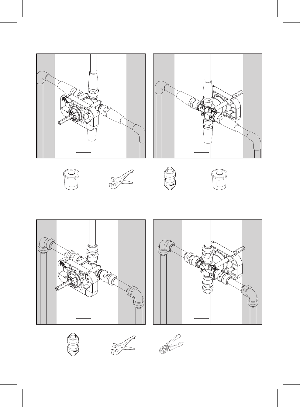
Preparation/Preparación
If you are replacing your plumbing valve, please review the four common plumbing methods illustrated
below: CPVC, PEX, IPS, and Copper. Remove the existing handle and valve trim before replacing your
valve. Please follow all local building and plumbing codes.
Si va a reemplazar la válvula de plomería, revise los cuatro métodos comunes de plomería ilustrados
a continuación: CPVC, PEX, IPS y cobre. Retire el reborde de la válvula y la manija existente antes
de reemplazar la válvula. Siga todos los códigos de plomería y construcción locales.muy ajustadas
comprometerán la integridad del sistema.
4
B. PEX-1
B. PEX-2
SharkBite Fittings
Conectores SharkBite
Full Circle Crimping Tool
Herramienta de engarzado de círculo completo
Tubing Cutter
Cortador de tuberías
B. PEX/PEX
SharkBite Fittings
Full Circle Crimping Tool
Tubing Cutter
You may also need/También puede necesitar:
Use 1/2" Copper or
IPS Pipe Only
Use sólo tubos de
COBRE o IPS de ½
pulg
Use 1/2" Copper or
IPS Pipe Only
Use sólo tubos de
COBRE o IPS de
½ pulg
A.CPVC-1
A.CPVC-2
CPVC Cement
Cemento para CPVC
SharkBite Fittings
Conectores SharkBite
Tubing Cutter
Cortador de tuberías
CPVC Cleaner
Limpiador de CPVC
A. CPVC/CPVC
P
i
p
e
J
o
i
n
t
C
o
m
p
o
u
n
d
CPVC Cement
SharkBite Fittings
Tubing Cutter
CPVC Cleaner
P
i
p
e
J
o
i
n
t
C
o
m
p
o
u
n
d
You may also need/También puede necesitar:
Use 1/2" Copper or
IPS Pipe Only
Use sólo tubos de
COBRE o IPS de ½
pulg
Use 1/2" Copper or
IPS Pipe Only
Use sólo tubos de
COBRE o IPS de ½
pulg

5
C. IPS-1
D. COPPER-1
C. IPS-1
D. COPPER-1
Tube Cutter
Cortador de tubos
Torch
Soplete
Tube Cutter
Cortador de tubos
Lead-free Solder Kit
Kit de soldadura sin plomo
Wire Brush
Cepillo de alambre
Shark Bite Fittings
Accesorios de tubería
SharkBite
C. IPS/IPS
D. COPPER/COBRE
Tube Cutter
Torch
Tube Cutter
Lead-free Solder Kit
Wire Brush
SharkBite Fittings
You may also need/También puede necesitar:
You may also need/También puede necesitar:

6
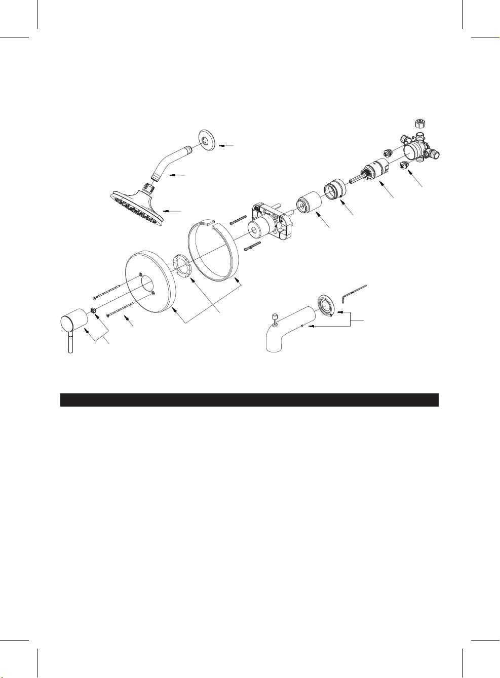
Includes/Incluye
NOTE: Please DO NOT use plumber’s putty on plas
tic compon
ents. Use silicone caulk if sealant is required.
NOTA: Por favor NO usar masilla de plomero en componentes plásticos. Usar pasta selladora de silicona si se
necesita un sellador.
A
B
C
F
H
G
L
J
I
K
E
D
Faucet Installation/Instalar el grifo
1
2
12
Note the installation distance between shower arm
(B), handle (E) and spout (K).
Note la distancia de instalación entre el brazo de la
regadera (B), la manija (E) y la vertedor (K).
Shut off main water supply before installation.
Antes de hacer la instalación cierre el suministro
principal de agua.
Shower arm flange
Brida del brazo de la ducha
Shower arm
Brazo de ducha
Showerhead
Cabeza de ducha
Plug
Tapón
Plaster guard
Placa para pared
Valve body
Cuerpo de la válvula
Hex wrench
Llave hexagonal
Spout Escutcheon
Escudo de bocallave de la boquilla
Escutcheon
Escudo
Spout
Vertedor
Handle
Manija
Escutcheon screw
Tornillo del escudete
B
E
K
30 in. Shower Only
76,2cm Ducha
solamente
48 in. Tub &
Shower
1,22m Bañera y
ducha
48 in. Shower Only
1,22m Ducha
solamente
30 in. Tub &
Shower
76,2cm Bañera
y ducha
8 in. min.
20,3 cm mín.

7
3a
3a 3a: Thin Wall Installation For Walls Thinner
Than 1/4 inch
The “Thin Wall” installation method is used when
the shower wall is less than 1/4 inches thick (such
as fiberglass tub surround) and will be the main
source of support for the valve. The plastic guard
remains against to the back side wall.
3a: Instalación en pared delgada: para paredes
de menos de ¼ pulg
El método de instalación en una pared delgada se
utiliza cuando la pared de la ducha tiene un grosor
inferior a 1/4 de pulgada (como el recubrimiento
de fibra de vidrio de una bañera) y será la principal
fuente de apoyo para la válvula. La placa de
plástico permanece contra la pared de la parte
trasera.
less than 1/4"
Menos de 6mm
3/4"
19mm
2-1/4" min.
57mm mín.
3-1/2" max.
89mm máx.
Faucet Installation/Instalar el grifo
Continued/Continuación
3b
3b 3b: Thick Wall Installation For Walls Thicker
Than 1/4 inch
The “Thick Wall” installation method is used when
the shower wall is greater than 1/4 inches thick.
“Thick Walls” are usually built up with materials
such as cement board, drywall, tile, etc. The valve
is secured by straps (not included) holding the
water inlet lines to the framing members (2X4’s).
The plaster guard is positioned so that it is flush
with the finished wall. This ensures that the valve
will be at the correct position to accept the trim.
3b: Instalación para pared gruesa: para
paredes de más de ¼ pulg
El método de instalación para pared gruesa se
usa cuando la pared de la ducha tiene un grosor
de más de ¼ de pulgada. Las paredes gruesas
habitualmente están hechas de materiales tales
como paneles de cemento, paneles de yeso,
azulejos, etc. La válvula se sujeta con correas
(no incluidas que amarran la toma de agua a los
postes de la armazón (2x4). La placa para pared
se coloca de manera que esté a nivel con la pared
terminada. Esto permite que la válvula tenga una
posición adecuada para poner la pieza exterior.
more than 1/4"
Más de 6mm
5-1/2"
140 mm

8
4
1
3
4
2
5a
45a
For pipe 4: Use 1/2" Copper or IPS Pipe Only. If soldering connections,
cartridge and integral stops must be removed to avoid heat damage
and reinstall when connection is completed and valve is cooled.
Para Tubo 4: Use sólo tubos de COBRE o IPS de ½ pulg. Si se
sueldan las conexiones, hay que retirar el cartucho y los topes
integrados para evitar que el calor los dañe y volver a instalarlos
cuando se haya terminado y enfriado la conexión.
Adjustable to accommodate the installation needs.
Ajustable para acomodar las necesidades de la
instalación.
5-3/8 in.
136,5mm
5-1/8 in.
130,2mm
3-1/16 in.
77,7mm
2-15/16"
75mm
Option
Opción
1
3
2
5b
1
6
5b 6
Install stub-out pipe (not included) for spout. Use
proper length stub-out pipe so pipe threads will
extend 1-1/2 to 2 inches beyond finished wall.
Instale la tubería saliente (no se incluye) para la
boquilla. Use una tubería saliente de de un largo
adecuado para que las roscas de la tubería se
extiendan de 3,81 cm a 5,08 cm más allá de la
pared acabada.
Note: Includes a valve plug so fixture can be used
in Shower Only applications.
NOTA: Incluye un tapón de válvula para que el
ensamble se pueda utilizar en aplicaiones de
solamente ducha.
2
6
1-1/2 in.~2 in.
3,81 a 5,08 cm
all
Faucet Installation/Instalar el grifo
Continued/Continuación

9
Faucet Installation/Instalar el grifo
Continued/Continuación
1
7
1
2
8
78
Install shower arm (B) and shower arm flange (A)
to vertical shower pipe elbow.
Instale el brazo de ducha (B) y la brida del brazo
de ducha (A) a la vertical del codo tubo de la
ducha.
Install the spout escutcheon (J) and spout (K),
secure it with the set screw.
Instale el escudo del vertedor (J) y el vertedor (K)
y sujételo con el tornillo de presión.
2
7
J
A
B
K
all
1
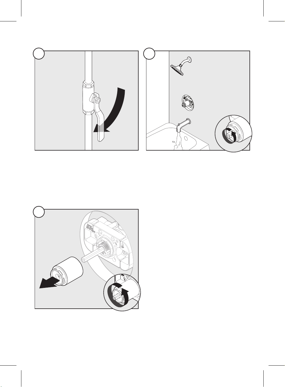
9
2
10
910
Remove plastic cap on plaster guard by twisting
clockwise.
Quite la tapa del protector de la pared.
Install showerhead (C) to shower arm (B). Hand
tighten showerhead.
Instale el cabezal de ducha (C) en el brazo de la
ducha (B). Apriete manualmente el cabezal de
ducha.
1
10
9
2
C
B
all
10
Faucet Installation/Instalar el grifo
Continued/Continuación
11
12
11 12
Turn on water and check for leaks.
Abra el suministro de agua y revise que no haya
fugas.
Turn on main water supply.
Abra el suministro de agua principal.
12
2
13
13
Remove valve sleeve.
Quite el manguito de la válvula.
1
13
11
Faucet Installation/Instalar el grifo
Continued/Continuación
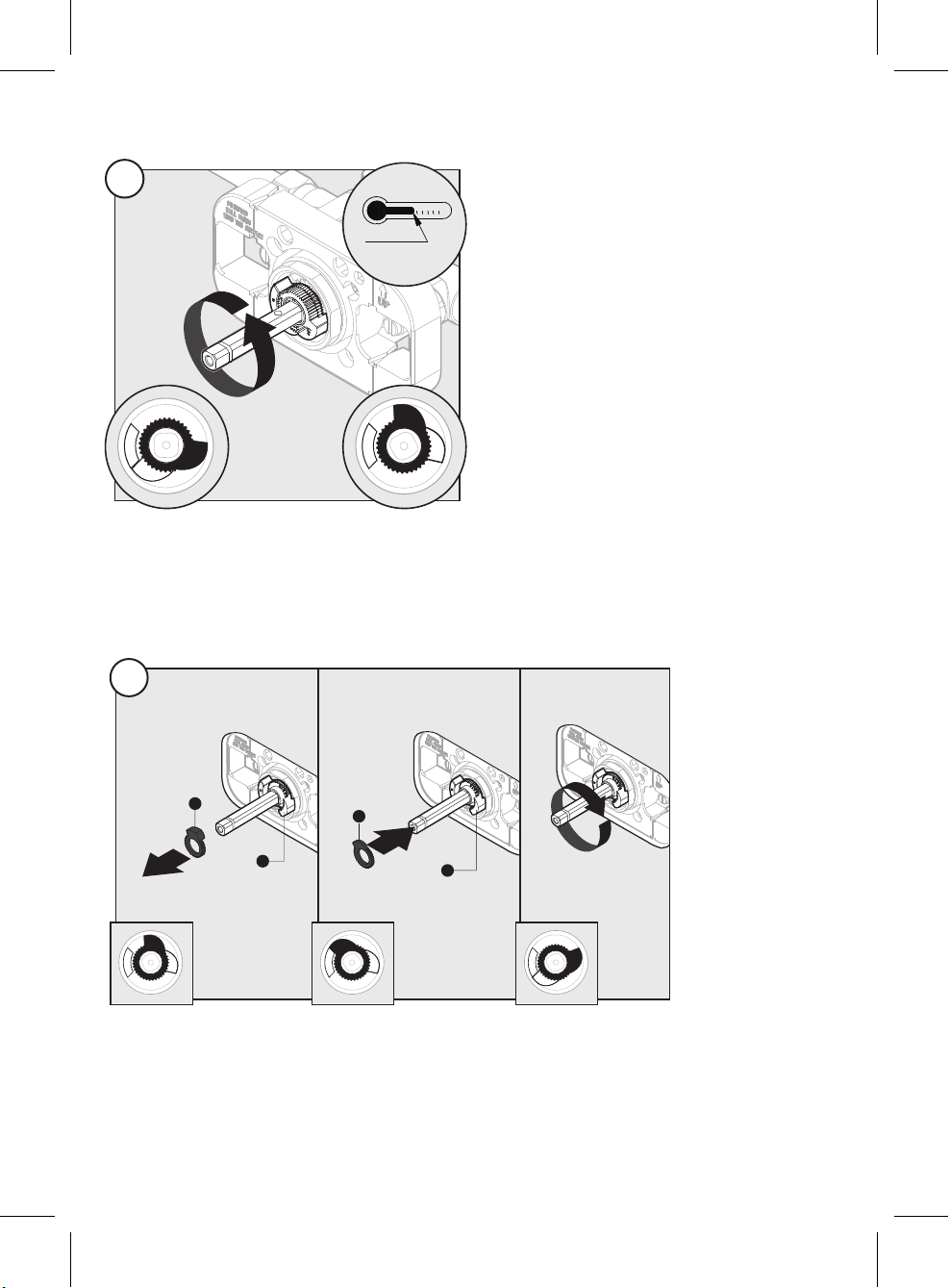
14
14 Turn the cartridge stem counterclockwise to
the full position. After several minutes, check
the temperature using the thermometer. Slowly
turn the cartridge stem clockwise to adjust the
maximum water temperature to the desired
temperature.
CAUTION:The maximum water temperature
should never be set above 120°F (49°C).
Gire completamente el vástago del cartucho en
el sentido contrario a las agujas del reloj. Espere
varios minutos y compruebe la temperatura con
el termómetro. Gire lentamente el vástago del
cartucho en el sentido de las agujas del reloj
para ajustar la temperatura máxima del agua a la
temperatura deseada.
PRECAUCIÓN: La temperatura máxima del agua
nunca debe estar por encima de 48,9°C (120°F).
120º F Max
49º C Max
14-1
b
c
a
14-3
b
ca
14-2
1
2
a
a
bb
15
15
Remove the red stop (a) and replace it against the stationary stop (c) to prevent the cartridge stem from
turning further. Turn the stem to the off position once the temperature is set.
NOTE: Do not move the blue stop (b). Seasonal maintenance of the maximum outlet temperature may be
required due to changes in groundwater temperature.
Retire el tope rojo (a) y colóquelo contra el tope fijo (C) para evitar que el vástago del cartucho gire más.
Gire el vástago a la posición de cerrado cuando haya seleccionado la temperatura.
NOTA: No mueva el tope azul (b). Es posible que se requiera un mantenimiento por temporada de la
temperatura de salida máxima debido a los cambios en la temperatura del agua del subsuelo.
red stop /
tope rojo red stop /
tope rojo
blue stop /
tope azul blue stop /
tope azul
b
c
a
15-1
b
c
a
15-2
b
c
a
15-3
12
Faucet Installation/Instalar el grifo
Continued/Continuación
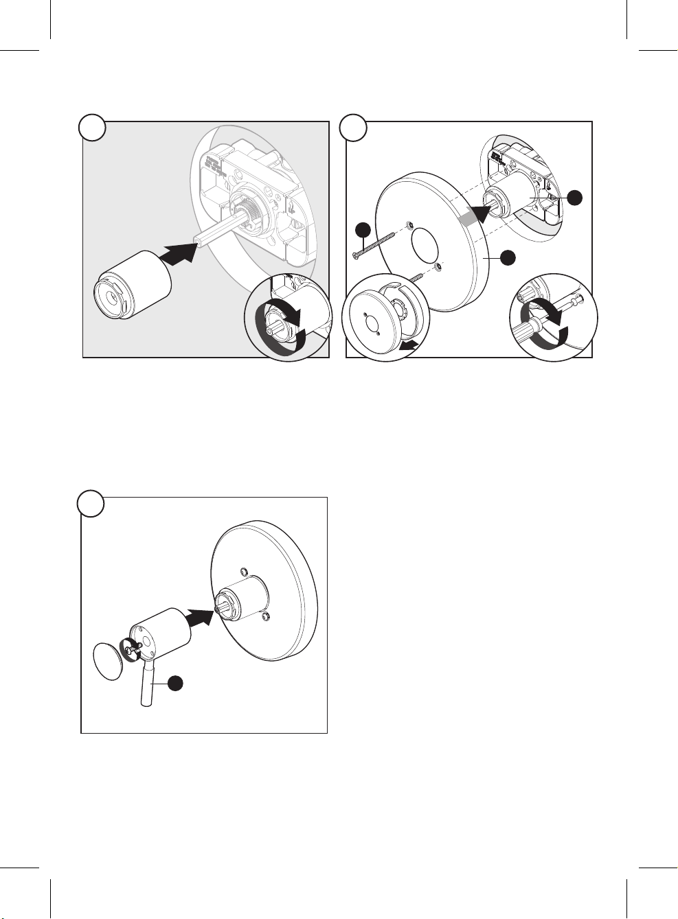
1
16
1
18
2
17
16
18
17
Install escutcheon (I) with screws (D) to valve body
(G).
Instale el escudete (I) con tornillos (D) en el cuerpo
de la válvula (G).
Replace valve sleeve.
Vuelva a poner el manguito de la válvula.
Install handle (E) to valve body. Secure with screw
and install handle cap.
Instale la manija (E) en el cuerpo de la válvula. Fije
con el tornillo e instale la tapa de la manija.
3
17-3
1
17-1
2
16
G
I
E
D

13
Back to back installation/Instalación de parte posterior contra parte posterior
2
1
2
ab180°
1 2
Replace valve sleeve.
Vuelva a poner el manguito de la válvula.
Remove red stop (a) and blue stop (b) and rotate
stem 180°. (The notch on cartridge stem facing
from up toward to down toward)
Retire el tope rojo (a) y el tope azul (b) y gire
el vástago 180°. (La muesca en el vástago del
cartucho pasa de mirar hacia arriba a mirar hacia
abajo).
1
b
ca
1
2
ab
3
Replace red stop (a) and blue stop (b). Replace
valve sleeve.
Reemplace el tope rojo (a) y el tope azul (b).
Vuelva a poner el manguito de la válvula.
3
b
ca

14
Gently clean the screen washer/Limpie con cuidado la arandela con ltro
2
1
3
2
4
2
1
3
2
4
Use a slotted screwdriver (not included) to
carefully remove the screen washer.
Use un destornillador de cabeza plana (no se
incluye) para retirar con cuidado la arandela con
filtro.
Reinstall the screen washer and showerhead (C).
Hand tighten showerhead.
Vuelva a colocar la arandela con filtro y el cabezal
de ducha (C). Apriete manualmente el cabezal de
ducha.
Use a clean strap wrench to remove the
showerhead (C) from shower arm (B).
Use una llave de correa limpia para retirar el
cabezal de ducha (C) del brazo de la ducha (B).
Gently clean the screen washer with a toothbrush
(not included).
Limpie con cuidado la arandela con filtro con un
cepillo de dientes (no se incluye).
B
C
C
1
1-1
2-1
1
4-1
15
1.
2.
3.
4.
5.
6.
7.
8.
9.
10.
11.
Parts Diagram/Diagrama de piezas
Part/Pieza Part #/Pieza # Description/Descripción
1 A66E563 Metal Handle Assembly / Ensamblaje de manija metálicas
2 A608550 Screw Set (3/16" -24 * 3-9/16" L) / Juego de tornillo (3/16" -24 * 3-9/16" L)
3 A66F548-S Escutcheon Assembly / Ensamblaje del Escudo
4 A103322 Sleeve / Manga
5 A103310-Z Retainer Nut / Tuerca de retención
6 A507190 Ceramic Disc Cartridge / Cartucho de disco de cerámica
7 A507040 Compression Stopper / Tope integrado
8 A019001-S Showerarm Escutcheon / Brazo de ducha del Escudo
9 A020002-S Shower Arm / Brazo de ducha
10 S1213606 Shower Head 1.75 gpm / Cabeza de ducha 1.75 gpm
11 A666934 Tub Spout with Diverter / Ensamblaje de vertedor

16
Maintenance/Mantenimiento
Your new faucet is designed for years of trouble-free performance. Keep it looking new by cleaning it
periodically with a soft cloth. Avoid abrasive cleaners, steel wool and harsh chemicals as these will dull
the finish and void your warranty.
Tu grifo nuevo está diseñado para funcionar por años, sin problemas. Límpialo periódicamente con un
paño suave para que luzca siempre como nuevo. Evita usar limpiadores abrasivos, esponjas de alambre
y químicos fuertes ya que ello opacará el acabado y anulará la garantía.
Troubleshooting/Solución de problemas
If you’ve followed the instructions carefully and your faucet still does not work properly, take these
corrective steps.
Si has seguido las instrucciones con cuidado pero tu grifo aún no funciona correctamente, toma las
siguientes medidas correctivas.
Problem/Problema Cause/Causa Action/Acción
Hot and cold are reversed. Lines reversed or cartridge installed
upside down.
Rotate the cartridge stem 180°
so that the notch is facing down
towards the drain.
Caliente y frío están invertidos. Las líneas están invertidas o el
cartucho está instalado en posición
invertida.
Gire el vástago del cartucho 180°,
de modo que la muesca mire hacia
abajo y hacia el desagüe.
There is no or a low water flow. One or both water supplies are not
turned on.
Turn both water supply valves
counterclockwise to the on
position.
No hay flujo de agua o hay un
flujo de agua bajo.
Uno o ambos suministros de agua no
están encendidos.
Gire ambas válvulas de suministro
de agua en dirección contraria
a las manecillas del reloj a la
posición de encendido.
There is leaking or dripping
from the spout when turning off.
Grommets not sealing properly.
Misplacement of temperature limit
stops.
Replace the cartridge.
Reinstall the temperature limit
stops over the cartridge stem
when the notch on the stem faces
upward.
Hay una fuga o el vertedor
gotea cuando se cierra.
Las arandelas no están selladas
correctamente. Mala colocación de los
topes de temperatura.
Sustituya el cartucho.
Vuelva a instalar los topes de
limitación de la temperatura sobre
el vástago del cartucho cuando la
muesca en el vástago mire hacia
arriba.
There is only hot water or only
cold water from the spouts.
Balancing spool stuck. Replace the cartridge.
Solo hay agua caliente o solo
hay agua fría de las boquillas.
El carrete de equilibrio está atascado. Reemplace el cartucho.

17
Problem/Problema Cause/Causa Action/Acción
Water comes out of the tub
spout and showerhead at the
same time when turning on.
If the pattern of the water flow
switches to the shower from the tub
spout, and the leak from the tub spout
is less than 0.01 GPM,
this is a normal occurrence. Or
consider the causes below:
The pipe used between the valve and
the tub spout is not 1/2 in. IPS, or the
COPPER pipe is incorrect.
The distance between the valve and
the showerhead is less than 49 in..
There is a restriction between the
valve and the tub spout.
The valve is installed upside down.
Change the pipe to 1/2 in. IPS
or COPPER. Relocate the
showerhead or valve to ensure the
minimal distance of 49 in..
Remove the tub spout and flush
out debris and/or replace the
undersized line or fittings.
Remove the valve and reinstall
in the proper orientation.
El agua sale por el vertedor de
la bañera y por la cabeza de la
ducha al mismo tiempo cuando
se abre.
Si el flujo de agua pasa desde el
surtidor de la bañera a la ducha y que
las fugas del surtidor de la bañera es
de menos de 0.01 GPM, esto es una
ocurrencia normal. O considere las
siguientes causas:
La tubería utilizada entre la válvula y
el surtidor de la bañera no es de 1/2
pulg. de IPS, o el tubo de cobre es
incorrecto.
La distancia entre la válvula y el
cabezal de la ducha es menor de 49
pulg..
Hay una restricción entre la válvula y
la boquilla de la bañera.
La válvula está instalada en posición
invertida.
Cambie el tubo a 1/2 pulg. de IPS
o cobre. Cambie el cabezal de
ducha o la válvula para asegurar
la distancia mínima de 49 pulg..
Retire la boquilla de la bañera
y elimine los desechos y/o
reemplace las tuberías o líneas de
tamaño menor.
Retire la válvula y vuelva a
instalarla con la orientación
correcta.

18
Manufacturer’s Limited Warranty
These Design Studio products are manufactured with superior quality standards and are warranted by
the manufacturer to be free from defects in material and workmanship under normal and reasonable use
in accordance with product instructions for a period of a) two (2) years from the date of original consumer
purchase or b) for commercial users, for one (1) year from the date of purchase.
Manufacturer will repair or replace any product or parts noted within the parts diagram found in the
installation manual for the product in question thereof that proves, upon inspection by Manufacturer
or Manufacturer’s representatives, to be defective in material or workmanship during the above stated
periods of warranty coverage. If replacement of the original part is not practical, Floor and Décor may
elect to replace with an equivalent part or product.
This warranty is limited to replacement parts only and does not cover or include labor changes or
damages incurred in installation, repair or replacement or any incidental or consequential damages
whatsoever, nor does it cover or include damages for personal injury, property damage or economic loss.
In no event shall liability exceed the purchase price of the faucet. Warranty parts orders may be subject to
shipping and handling charges.
Use of abrasive cleaners will void the warranty. Avoid abrasive cleaners, steel wool, or harsh chemicals.
These will dull the finish and void your warranty.
To make a warranty claim please contact Manufacturer’s customer service care team at 1-888-328-2383.
One of our team members will be glad to assist you. Proof of purchase (original sales receipt) from the
original consumer purchaser must be made available for all warranty claims.
Additional disclaimers
MANUFACTURER SHALL NOT BE LIABLE FOR LOSS OF USE OR ANY OTHER INCIDENTAL,
SPECIAL CONSEQUENTIAL COSTS, EXPENSES, LOSS OF INCOME OR PROFITS, OR OTHER
SIMILAR DAMAGES INCURRED BY THE PURCHASER.
SOME STATES DO NOT ALLOW THE EXCLUSION OR LIMITATION OF INCIDENTAL OR
CONSEQUENTIAL DAMAGES, SO THE ABOVE LIMITATION OR EXCLUSION MAY NOT APPLY TO
THE PURCHASER. THIS WARRANTY GIVES YOU SPECIFIC RIGHTS, AND YOU MAY ALSO HAVE
OTHER RIGHTS, WHICH MAY VARY, FROM STATE TO STATE. WITH THE EXCEPTION OF ANY
WARRANTIES IMPLIED BY STATE LAW AS HEREBY LIMITED, THE WARRANTIES SET FORTH
ABOVE ARE PURCHASER’S SOLE AND EXCLUSIVE REMEDIES.
IF ANY IMPLIED WARRANTY ARISES UNDER APPLICABLE LAW, THEN ANY AND ALL IMPLIED
WARRANTIES ARE LIMITED IN DURATION TO THE DURATION OF THIS WRITTEN WARRANTY TO
THE EXTENT ALLOWED BY APPLICABLE LAW. SOME STATES DO NOT ALLOW LIMITATIONS ON
HOW LONG AN IMPLIED WARRANTY LASTS, SO THE ABOVE LIMITATION MAY NOT APPLY TO
YOU.

19
Garantía limitada del fabricante
Estos productos Design Studio se fabrican con estándares de calidad superiores y son garantizados,
por parte del Fabricante, de estar libres de defectos en mano de obra y en los materiales con los que
están fabricados y bajo un uso normal y razonable, de acuerdo con las instrucciones del producto y por
un período de a) dos (2) años a partir de la fecha de compra original por parte del consumidor, o b) para
usuarios comerciales por un período de un (1) año a partir de la fecha de compra.
El Fabricante reparará o reemplazará cualquier producto o piezas que se indiquen en el diagrama de
piezas, el cual se encuentra en el manual de instalación, del producto en cuestión y que demuestre,
después de la inspección realizada por el Fabricante o los representantes del Fabricante, que tiene
defectos en los materiales o mano de obra, dentro de los plazos indicados en la de cobertura de la
garantía. Si el reemplazo de la pieza original no es práctico, el Fabricante puede optar por reemplazarla
con una pieza o producto equivalente.
Esta garantía se limita a piezas de repuesto solamente y no cubre ni incluye cambios de detalles en
mano de obra o daños incurridos en la instalación, reparación, reemplazo o cualquier daño incidental
o consecuente, ni cubre ni incluye daños por lesiones personales, daños a la propiedad o pérdidas
económicas. En ningún caso, la responsabilidad excederá el precio de compra del grifo. Los pedidos de
piezas en garantía pueden estar sujetos a gastos de envío y transporte.
El uso de limpiadores abrasivos anulará la garantía. Evite usar limpiadores abrasivos, esponjillas de
alambre o productos químicos agresivos. Esto opacará el acabado y anulará la garantía.
Para hacer un reclamo bajo garantía, por favor comuníquese con el equipo de atención al cliente del
Fabricante al 1-888-328-2383. Uno de los miembros del equipo le ayudará con gusto. El comprobante
de compra (recibo de compra original), del comprador original, debe estar disponible para todas las
reclamaciones de garantía.
Descargos de responsabilidad adicionales
EL FABRICANTE NO SERÁ RESPONSABLE DE PÉRDIDAS, COSTOS, GASTOS, PÉRDIDA DE
INGRESOS O GANANCIAS O DAÑOS SIMILARES DERIVADOS, ESPECIALES, INDIRECTOS,
INCIDENTALES O PUNITIVOS DE NINGUNA ÍNDOLE, INCURRIDOS POR EL COMPRADOR.
ALGUNOS ESTADOS NO PERMITEN LA EXCLUSIÓN O LIMITACIÓN DE DAÑOS INCIDENTALES
O DERIVADOS, DE MODO QUE, LA LIMITACIÓN O EXCLUSIÓN QUE PRECEDE PUEDE NO SER
APLICABLE AL COMPRADOR. ESTA GARANTÍA LE OTORGA DERECHOS ESPECÍFICOS Y USTED
PUDIERA TENER OTROS DERECHOS, QUE PUEDEN VARIAR DE ESTADO A ESTADO, CON
EXCEPCIÓN DE CUALQUIER GARANTÍA IMPLÍCITA POR LA LEY ESTATAL COMO LIMITADA POR
LA PRESENTE. LAS GARANTÍAS INDICADAS EN ESTE DOCUMENTO SON RECURSOS ÚNICOS Y
EXCLUSIVOS DEL COMPRADOR.
SI CUALQUIER GARANTÍA IMPLÍCITA SE PRESENTA BAJO LA LEY APLICABLE, ENTONCES,
CUALQUIERA Y TODAS LAS GARANTÍAS IMPLÍCITAS, ESTÁN LIMITADAS EN DURACIÓN, A LA
DURACIÓN DE ESTA GARANTÍA ESCRITA EN LA MEDIDA PERMITIDA POR LA LEY APLICABLE.
ALGUNOS ESTADOS NO PERMITEN LIMITACIONES SOBRE LA DURACIÓN DE LAS GARANTÍAS
IMPLÍCITAS, POR LO QUE LA LIMITACIÓN ANTERIOR PUEDE NO APLICARSE.
Printed in China
Impreso en China
This manual suits for next models
3
Table of contents
Popular Bathroom Fixture manuals by other brands

Porcelanosa
Porcelanosa Noken Square 100081777 N140140032 manual

Hans Grohe
Hans Grohe Croma 100 Vario 28535000 Assembly instructions

Kohler
Kohler K-702400 installation guide

TRUEFORM
TRUEFORM NOLITA installation instructions

Ropox
Ropox 40-40125 Mounting instruction

F.lli Frattini
F.lli Frattini 90912 Installation and use instructions and warnings


