Studio Elektronike Rijeka STER PMU Instruction manual

QUICK START MANUAL


STER PMU Quick Start Manual rev. 1.1.2355
Studio Elektronike Rijeka d.o.o. [STER]
Radmile Matejčić 10
HR-51000 Rijeka, Croatia
Web: www.wamster.net
E-mail: [email protected]
Mark on your equipment certifies that this equipment meets the requirements of the EU
(European Union) concerning safety and interference causing equipment regulations
© 2010-2016 STUDIO ELEKTRONIKE RIJEKA
STER PMU and WAMSTER are trademarks of Studio Elektronike Rijeka. No part of this publication may be
reproduced or utilized in any form or by any means without a written permission from Studio Elektronike Rijeka.
Visit www.wamster.net for the latest version of this and other applicable manuals. You may need to log in using
your account credentials.


Document Revisions Record
Revision
DESCRIPTION OF CHANGE
APPROVED
BY
DATE
APPROVED
1.0.885
Initial publication
DB
2011-10-31
1.0.982
Updated with:
Detailed operating procedures
Wiring configurations
Wamster manual
Other minor fixes
DB
2012-01-25
1.0.1100
Updated with:
IEEE C37.118 configuration
DB
2012-04-23
1.0.1113
Updated Communication setup
DB
2012-05-08
1.0.1244
Added support for the Event section
DB
2012-08-31
1.0.1317
Updated with:
GPRS modem configuration
DB
2012-10-24
1.0.1346
Minor fixes
DB
2012-11-06
1.1.2355
Various updates in the web interface chapter:
Trends
Waveforms
Harmonics
DB
2016-02-29


STER PMU Quick Start Manual Table of Contents
3
Table of contents
1Introduction ..................................................................................................................................................... 5
1.1 Main Features .............................................................................................................................................. 5
1.2 Safety considerations................................................................................................................................... 6
1.3 Applicable standards.................................................................................................................................... 6
2Description ....................................................................................................................................................... 7
2.1 Front panel................................................................................................................................................... 7
2.2 Connector panel........................................................................................................................................... 8
2.3 Bottom view................................................................................................................................................. 9
2.4 Accessories................................................................................................................................................... 9
2.4.1 Standard accessories............................................................................................................................. 9
2.4.2 Optional accessories ........................................................................................................................... 10
3Getting started ............................................................................................................................................... 11
3.1 Configuring and cabling communication equipment................................................................................. 11
3.2 Preparing the Serial to Ethernet converter................................................................................................ 11
3.2.1 Performing a factory reset of the device ............................................................................................ 12
3.2.2 Configuring the SENA PS110 using a serial cable ................................................................................ 12
3.2.3 Configuring the Serial to Ethernet converter through the web interface........................................... 16
3.3 Cabling and connecting the device ............................................................................................................ 17
3.3.1 Connecting the power supply and powering on ................................................................................. 17
3.3.2 Connecting the GPS receiver............................................................................................................... 17
3.3.3 Cabling setup when using the GPRS modem ...................................................................................... 18
3.3.4 Cabling setup when using the Ethernet converter ............................................................................. 19
3.4 Configuring the device for first use............................................................................................................ 20
3.4.1 Main screen......................................................................................................................................... 20
3.4.2 Setup menu......................................................................................................................................... 21
3.4.3 Communication Setup menu .............................................................................................................. 21
3.4.4 Managing the device using the Wamster web interface .................................................................... 23
3.4.5 Powering off........................................................................................................................................ 23
4Working with the instrument ......................................................................................................................... 25
4.1 Changing measurement settings ............................................................................................................... 25
4.1.1 Measurement Setup screen................................................................................................................ 25
4.2 Voltage measurement ............................................................................................................................... 25
4.3 Current Measurement ............................................................................................................................... 26
4.3.1 Current range and transformation ratio ............................................................................................. 26
4.4 General considerations for wiring.............................................................................................................. 27
4.4.1 Connecting voltage terminals ............................................................................................................. 27
4.4.2 Connecting current terminals ............................................................................................................. 28

STER PMU Quick Start Manual Table of Contents
4
4.5 Wiring configurations................................................................................................................................. 28
4.5.1 Connecting to Low-Voltage power systems........................................................................................ 28
4.5.2 Connecting to Mid- and High-Voltage power systems ....................................................................... 30
4.6 Synchronization ......................................................................................................................................... 31
4.7 Frequency .................................................................................................................................................. 31
5Instrument maintenance ................................................................................................................................ 33
5.1 Changing batteries ..................................................................................................................................... 33
5.2 Safety considerations................................................................................................................................. 33
5.3 Batteries..................................................................................................................................................... 34
5.4 Power supply considerations ..................................................................................................................... 34
5.5 Cleaning ..................................................................................................................................................... 34
5.6 Periodic calibration .................................................................................................................................... 35
5.7 Service........................................................................................................................................................ 35
5.8 Troubleshooting......................................................................................................................................... 35
6Using the Wamster web interface .................................................................................................................. 37
6.1 Minimal configuration ............................................................................................................................... 37
6.2 Signing in to Wamster................................................................................................................................ 37
6.3 Overview .................................................................................................................................................... 38
6.3.1 Device Settings form ........................................................................................................................... 39
6.3.2 General settings .................................................................................................................................. 40
6.3.3 Local triggering.................................................................................................................................... 41
6.3.4 Rewiring Rules..................................................................................................................................... 42
6.3.5 Scaling/Rotation Settings .................................................................................................................... 42
6.3.6 Digital I/O ............................................................................................................................................ 43
6.4 Device comparison..................................................................................................................................... 44
6.4.1 Setting the reference device for comparison ..................................................................................... 44
6.4.2 Switching between real-time and historical views ............................................................................. 45
6.5 Configuring and viewing triggered events ................................................................................................. 45
6.6 Analyzing Trends ........................................................................................................................................ 46
6.6.1 Data settings sidebar........................................................................................................................... 47
6.6.2 View settings toolbar .......................................................................................................................... 48
6.6.3 Chart interaction ................................................................................................................................. 49
6.6.4 Chart annotations ............................................................................................................................... 49
6.7 Waveforms................................................................................................................................................. 49
6.8 Harmonics .................................................................................................................................................. 50
6.9 Exporting and downloading data............................................................................................................... 50
6.10 Remote access ........................................................................................................................................... 52
6.11 Support page.............................................................................................................................................. 53

STER PMU Quick Start Manual Introduction
5
1Introduction
STER PMU is a handheld synchrophasor measurement unit, equipped with a rechargeable battery pack, GPS for
time source, GPRS modem or Serial to Ethernet converter for remote data reporting, and SD card slot for local
storage of 5 months of synchrophasor measurements.
It is designed to provide an easy to setup solution for remote measurement and data acquisition. Combined with
the WAMSTER cloud storage system, it provides instant access to measured data through an ad-hoc, zero
configuration network.
Figure 1.1: Ster PMU device
1.1 MAIN FEATURES
4 voltage channels with wide measurement range: 0 ÷ 1000 Vrms, CAT III / 1000 V.
4 current channels with support for automatic clamp recognition
1
.
Simultaneous 8 channels - 16bit AD conversion for accurate power measurements (minimal phase shift error).
Up to 4 hours of autonomous (battery) supply.
8Mb of internal flash memory for 77 minutes of synchrophasor data, or 32Gb of external flash memory (SD
card) for more than 5 months of synchronous reporting speed measurements
GPRS modem provided for remote connection to the Wamster server.
1
with selected Smart clamp types
STER PMU Quick Start Manual Introduction
6
1.2 SAFETY CONSIDERATIONS
To ensure operator safety while using the STER PMU instruments and to minimize the risk of damage to the
instrument, please note the following general warnings:
The instrument is designed to ensure maximum operator safety. Usage in a way other than specified in
this manual may increase the risk of harm to the operator!
Do not use the instrument and/or any accessories if there is any damage visible!
The instrument contains no user serviceable parts. Only an authorized dealer can carry out service or
adjustment!
All normal safety precautions have to be taken in order to avoid risk of electric shock when working on
electrical installations!
Only use approved accessories available from your distributor!
Instrument contains rechargeable NiMh batteries. The batteries should only be replaced with the same
type as defined on the battery placement label or in this manual. Do not use standard batteries while
power supply adapter/charger is connected, otherwise they may explode!
Hazardous voltages exist inside the instrument. Disconnect all test leads, remove the power supply cable
and switch off the instrument before removing battery compartment cover.
In hot (> 40 °C) environments, the battery lid screw might reach the maximum allowed temperature for
metal part of handle. In such environment it is advisable not to touch the battery cover during or
immediately after the charging.
Maximum voltage between any phase and neutral input is 1000 VRMS. Maximum voltage between phases
is 1730 VRMS.
Always short unused voltage inputs (L1, L2, L3, GND) with the neutral (N) input to prevent measurement
errors and false event triggering due to noise coupling.
1.3 APPLICABLE STANDARDS
STER PMU device is designed and tested in accordance with the following standards:
Electromagnetic compatibility(EMC)
EN 61326-2-2: 2006
Electrical equipment for measurement, control and laboratory use.
Emission: Class A equipment (for industrial purposes)
Immunity for equipment intended for use in industrial locations
Safety (LVD)
EN 61010-1: 2001
Safety requirements for electrical equipment for measurement,
control and laboratory use
Measurement methods
TBD
NOTE ABOUT EN AND IEC STANDARDS:
Text of this manual contains references to European standards. All standards of EN 6XXXX (e.g. EN 61010) series
are equivalent to IEC standards with the same number (e.g. IEC 61010) and differ only in amended parts required
by European harmonization procedure.

STER PMU Quick Start Manual Description
7
2Description
2.1 FRONT PANEL
1
2
3
4
5
6
7
Figure 2.1: Front panel
Front panel layout:
1
LCD
Graphic display with LED backlight, 320 x 200 pixels.
2
F1 –F4
Soft function keys. Their function is indicated for each screen separately, at the
bottom of the LCD display.
3
ARROW keys
Move cursor and select parameters.
4
ENTER key
Confirms new settings, step into submenu.
5
ESC key
Exits any procedure, exit from submenu.
6
LIGHT key
LCD backlight on/off (backlight automatically turns off after 15 minutes if no key
action occurs).
7
ON-OFF key
Turns on/off the instrument.
STER PMU Quick Start Manual Description
8
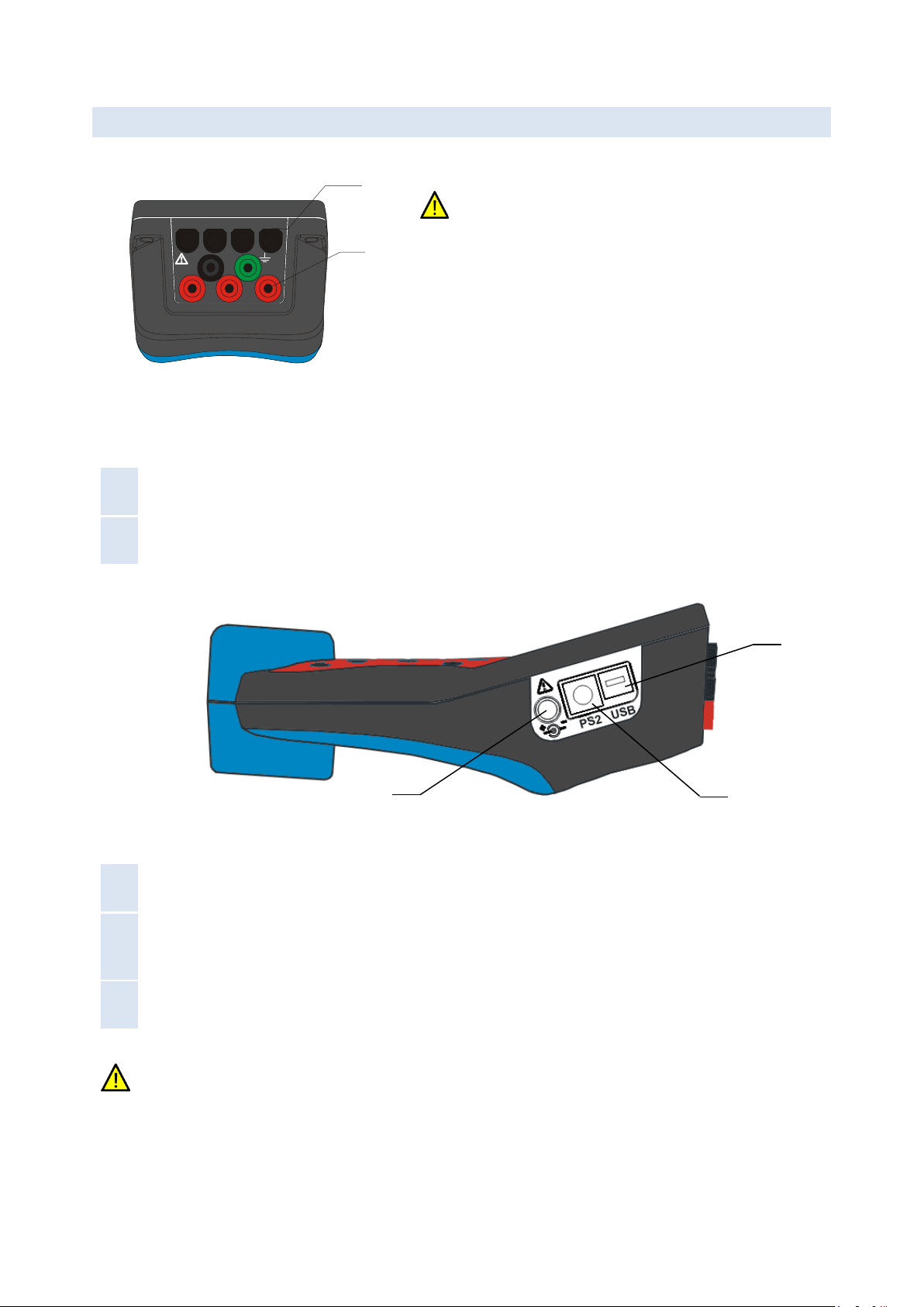
2.2 CONNECTOR PANEL
IN I3 C B AI1
L1
L3C
N
A
I2
L2B
1
2
Warning!
Use safety test leads only!
Max. permissible voltage between voltage input terminals and
ground is 1000 VRMS.
Max. permissible voltage between voltage input terminals is
1730 VRMS
Figure 2.2: Top connector panel
Top connector panel layout:
1
CURRENT
TERMINALS
Clamp-on current transformers (I1, I2, I3, IN ) input terminals.
2
VOLTAGE
TERMINALS
Voltage (L1, L2, L3, N, GND) input terminals.
Figure 2.3: Side connector panel
Side connector panel layout:
1
External power
socket
12 VDC, 1.2A power supply socket.
2
PS2 type
GPS/auxiliary
power connector
Composite connector for GPS module input and auxiliary model power supply
output. Provided Y-split PS2 cable allows backup battery power supply to be used for
external equipment (GPRS/Ethernet modem).
3
USB/serial
modem connector
Serial data connector for the GPRS/Ethernet modem.
Use the provided cables and adapters only to avoid damaging the equipment. Although standard PS2 and
USB connectors are used, their terminals are arranged to allow additional signals (like modem power
supply), and are NOT SUITED for use with PC or similar equipment.
3
2
1

STER PMU Quick Start Manual Description
9
2.3 BOTTOM VIEW
MI 2792
CAT III 1000V IP40
Figure 2.4: Bottom view
Bottom view layout:
1
Battery compartment
To replace the batteries, unscrew the lid screw using a large screwdriver or a
coin. Refer to the Instrument maintenance chapter for details.
2
Serial number label
Device serial number.
Warning! Refer to the Instrument maintenance chapter for details about replacing the batteries. Never
replace the batteries while the device is connected to the power supply and measurement leads.
2.4 ACCESSORIES
2.4.1 STANDARD ACCESSORIES
Table 2.1: STER PMU standard accessories
Description
Pcs.
Current transformer 5 A / 1 V (A 1037)
1
Test probe (CAT II), red
3
Test probe (CAT II), black
1
Crocodile clip, red
3
Crocodile clip, black
1
Crocodile clip, green
1
Voltage measurement cable, red
3
1
2
STER PMU Quick Start Manual Description
10
Voltage measurement cable, black
1
Voltage measurement cable, green
1
USB to female DB9 cable
1
Male DB9 to male DB9 cable
1
12 V / 1.2 A Power supply adapter for the STER PMU device
1
NiMH rechargeable battery, type HR 6 (AA)
6
Soft carrying bag
1
Instruction manual for STER PMU
1
GPS Receiver
1
Y-split cable with a connector modem power supply
1
Crossover UTP patch cable
1
GPRS Modem1
1
SENA PS110 Serial to Ethernet converter1
1
Power supply adapter for the SENA PS110 Serial to Ethernet converter1
1
SENA PS110 Quick Start Guide CD-ROM
1
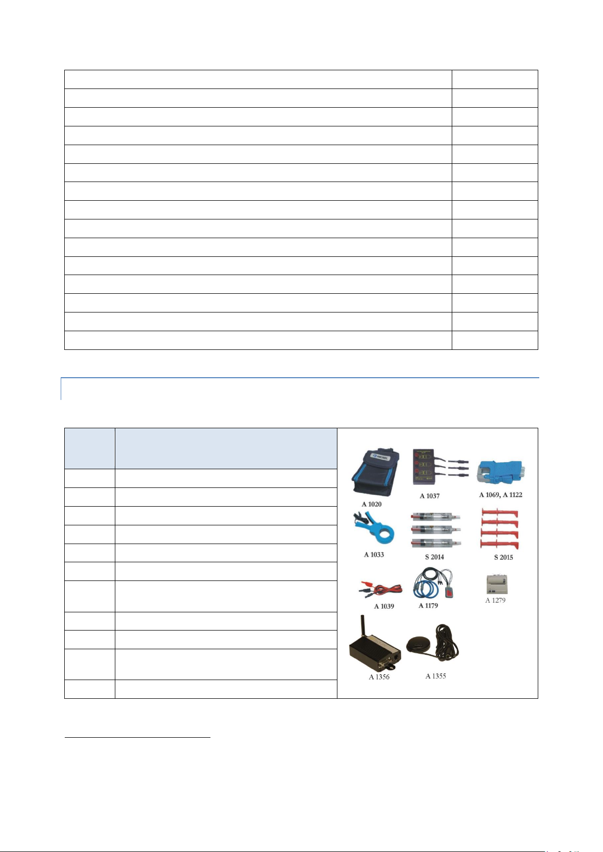
2.4.2 OPTIONAL ACCESSORIES
Table 2.2: STER PMU optional accessories
Ord.
code
Description
A 1020
Small soft carrying bag
A 1033
Current clamp 1000 A / 1 V
A 1227
Flexible current clamp 3000 A / 300 A / 30 A
A 1039
Connection cable for current clamp
A 1069
Mini current clamp 100 A / 1 V
A 1122
Mini current clamp 5 A / 1 V
A 1179
3-phase flexible current clamps
2000 A / 200 A / 20 A
S 2014
Safety fuse adapters
S 2015
Safety flat clamps
A 1281
Current clamp
5 A / 100 A / 1000 A
A 1356
UMTS (3G) modem
1
Depends on the actual order specification

STER PMU Quick Start Manual Getting started
11
3Getting started
3.1 CONFIGURING AND CABLING COMMUNICATION EQUIPMENT
STER PMU can connect to the Wamster server using two modem types:
1. Serial to Ethernet converter, which allows connection over the wired, reliable Ethernet connection, or
2. GPRS modem, which allows remote connection using the mobile GPRS network.
First communication option, the Serial to Ethernet converter, needs to be configured according to the switching
and routing equipment it will be connected to, by connecting it to a PC as described in the following chapter.
If you are using the GPRS modem for communication, you can skip this part and continue with the next chapter
(3.3 Cabling and connecting the device).
3.2 PREPARING THE SERIAL TO ETHERNET CONVERTER
If the GPRS modem is used for remote communication, STER PMU will automatically configure all the
necessary parameters. In that case, you can skip this chapter and continue powering on the device.
For the SENA PS110 Serial to Ethernet converter, it is important to manually configure its IP address to match the
appropriate LAN subnet before connecting it. This configuration needs to be done using a PC, either through an
RS232 serial connection while the PS110 device is in Console mode, or by connecting the device to a PC using a
crossover LAN cable.
Before configuration, you need to determine which IP settings the device should have, in order to operate when
connected to your LAN equipment. If the device is connected to a network with a DHCP server (most routers
support this protocol) the IP settings are assigned automatically by the DHCP server.
Alternatively, a static IP can be configured to match advanced network requirements, in which case there are four
parameters which need to be known before continuing:
1
IP address
A static IP address acts as a permanent identification number. It is required that the
selected IP address is both unique and valid in a network environment.
2
Subnet mask
A subnet represents the range of IP addresses for all the network hosts in one
geographic location, such as a building or local area network (LAN). PS110 will use
the subnet mask setting to verify the origin of all packets. If the desired TCP/IP host
specified in the packet is in the same geographic location (on the local network
segment) as defined by the subnet mask, the Pro Series will establish a direct
connection. If the desired TCP/IP host specified in the packet is not identified as
belonging on the local network segment, a connection is established through the
given default gateway.
3
Default gateway
A gateway is a network point that acts as a portal to another network. This point is
usually the computer or computers that control traffic within a network or a local ISP
(Internet service provider). PS110 uses the IP address of the default gateway
computer to communicate with hosts outside the local network environment.
4
Primary and
Secondary DNS
The DNS (Domain Name System) server is used to locate and translate the correct IP
address for a requested web site address. A domain name is the web address (i.e.
www.yahoo.com) and is usually easier to remember. The DNS server is the host that
can translate such text-based domain names into numeric IP addresses for a TCP/IP
connection.
The IP address of the DNS server must be able to access the host site with the
provided domain name. The Pro Series provides the ability to configure the required
IP addresses of both the Primary and Secondary DNS server addresses (the
secondary DNS server is specified for use when the primary DNS server is
unavailable).

STER PMU Quick Start Manual Getting started
12
If unsure, please refer to your network administrator before continuing. Specifying wrong IP settings is the
most likely reason for connection issues.
3.2.1 PERFORMING A FACTORY RESET OF THE DEVICE
Before starting, it is advisable to make a full factory reset of the PS110 device.
To do that, make sure that the device is powered on by connecting the provided power charger to the device. The
Power LED on the opposite side of the device should indicate that the device is powered on.
SENA PS110
AC/DC adaptor
Figure 3.1: Powering on the PS110 modem
To reset all settings to their defaults, press the factory reset switch located on the bottom side of the device and
hold it for at least 5 seconds.
3.2.2 CONFIGURING THE SENA PS110 USING A SERIAL CABLE
To configure the SENA PS110 through a serial port, a PC with a serial RS232 COM port and a terminal application
must be available. A DB9 female to female serial cable is provided with the device for this connection type.
1. Set the position of the DIP switch for serial mode (located at the back side of the device, next to the Ethernet
connector) to RS-232 mode. DIP positions should match the following picture:
Figure 3.2: Serial Mode switch positions for the RS232 connection
2. Connect serial cable to the serial port of your PC first, and then connect it to the serial port of the device, using
the provided DB9 female to female cable.
SENA PS110
AC/DC adaptor
To PC
Serial port
Switched to
Console mode
RS-232 mode
Figure 3.3: Connecting the PS110 device to a PC serial port

STER PMU Quick Start Manual Getting started
13
3. Make sure that the PS110 device is powered on.
4. Switch the Data/Console switch, located next to the serial port, to Console mode (indicated in figure above).
5. Start a terminal emulation software (i.e. HyperTerminal) and configure the serial connection using following
parameters:
Baud rate
9600
Data bits
8
Parity
None
Stop bits
1
Flow control
None
Figure 3.4: HyperTerminal serial connection settings dialog
6. Open the connection.
7. Direct the input to the console, and press the ENTER key to check if the device is communicating. Device
should respond with a ProSeries login prompt.
8. Enter username and password to log into the device. The factory default user settings are as follows:
Login
root
Password
root
Figure 3.5: Default user credentials for PS110
9. Type editconf and press Enter. PS110 will enter the text-driven menu interface for setting device
configuration:

STER PMU Quick Start Manual Getting started
14
Figure 3.6: Device configuration setup main menu
To select a menu item, type the preceding menu number and press the ENTER key. Use the ESC key to exit and
return to the previous menu. All the parameters can be stored into the non-volatile memory space of the device,
but only if the save command is issued.
10. Setting network configuration.
PS110 serial to Ethernet converter requires a valid IP address to operate within the user's network environment. If
the IP address is not readily available, contact the system administrator to obtain a valid IP address for the device.
Enter Network configuration menu from the main menu by typing 1and pressing Enter. Then, enter the IP
configuration submenu. The following menu items should appear:
Figure 3.7: IP configuration example
IP mode can be one of the previously mentioned modes:
Static IP (requires manual parameter configuration)
DHCP (Dynamic Host Configuration Protocol): automatic configuration using a DHCP server
When in static IP mode, the IP address must be entered manually for each device separately. If the device is moved
to another network location, a new IP address will probably be needed. On the other hand, DHCP allows all the
parameters, including the IP address, subnet mask, Gateway, and DNS servers to be automatically configured
when the IP address is assigned.
To change IP configuration mode type 1and press Enter. The following selection should appear:
Figure 3.8: IP mode selection
The asterisk on the right side of the selection item indicates the current setting. Type 1for using static IP mode, or
type 2for using DHCP IP mode and press Enter. If you have selected DHCP IP mode return to the main menu by

STER PMU Quick Start Manual Getting started
15
pressing ESC key and continue with the Serial port configuration, otherwise continue setting up other static IP
mode parameters.
Next parameter to set is the device IP address. Press 2and then Enter. Type the device IP address in the NEW field
and press Enter.
Figure 3.9: Setting up IP address
Repeat the last step (with the appropriate menu item number) for setting up Subnet mask, Default gateway and
DNS servers.
11. Serial port configuration.
Once the IP Configuration is completed, return to the main menu on Fig. 3.6 by pressing Esc as needed. Enter Serial
port configuration by pressing 2, followed by Enter.
Figure 3.10: Serial port configuration overview
In the serial port configuration overview select the ordinal number of the serial port to configure. On a PS110,
there will only be a single port shown. Press 1and Enter to configure the port, then enter the Host mode
configuration menu.
11.1.Host mode configuration
Host mode configuration parameters should match the following table:
Host mode
Modem emulation
Command echo delay
0
Default echo mode
Disable
Default data mode
Raw TCP
Once set, the Host mode configuration menu should appear as shown on the picture below:
STER PMU Quick Start Manual Getting started
16
Figure 3.11: Host mode configuration parameters
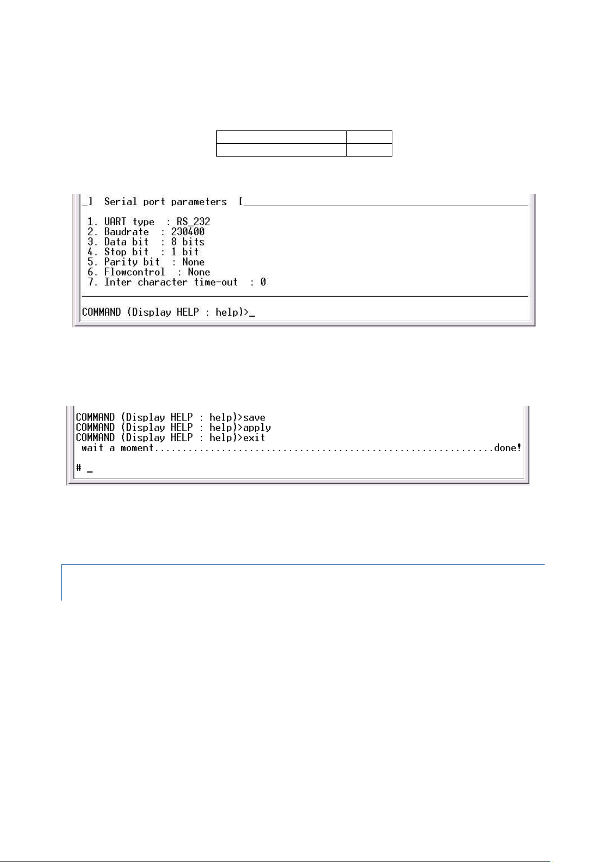
11.2.Serial port parameters
Several Serial port parameters have to be changed as follows:
Baud rate
230400
Inter character time-out
0
Other parameters should be left unchanged. The configuration should match the following picture.
Figure 3.12: Serial port parameters
12. Save and apply changes by entering the save command, followed by the apply command. The device will
save new configuration settings in the non-volatile memory and apply them.
13. Finally, exit from the text-driven configuration menu interface by entering the exit command.
Figure 3.13: Save, apply and exit to finish configuration
14. When finished, disconnect the serial cable and move the Data/Console switch to Data position. Modem is
now ready to be connected to the device.
3.2.3 CONFIGURING THE SERIAL TO ETHERNET CONVERTER THROUGH THE WEB
INTERFACE
To configure Serial to Ethernet converter through the web interface please refer to the SENA PS110 user manual
on the accompanied CD-ROM.
Table of contents


