Studio Technologies Dante 5402 User manual

50703-0821, Issue 3
Copyright © 2021 by Studio Technologies, Inc., all rights reserved
studio-tech.com
User Guide
Issue 3. August 2021
This User Guide is applicable for serial numbers
M5402-00151 and later with Main MCU Firmware 1.01 and later
Model 5402
Dante® Leader Clock
with GNSS Synchronization

This page intentionally left blank.

Model 5402 User Guide Issue 3, August 2021
Studio Technologies, Inc. Page 3
Model 5402
DANTE LEADER CLOCK WITH GNSS SYNCHRONIZATION
Table of Contents
Revision History ..................................................................................................................................... 4
Introduction ............................................................................................................................................ 5
Installation .............................................................................................................................................. 8
Dante Configuration ............................................................................................................................... 11
Model 5402 Configuration ......................................................................................................................13
Operation ...............................................................................................................................................31
Technical Notes .....................................................................................................................................39
Specifications .........................................................................................................................................43
Appendix A–Compatible Sync Input Sources ........................................................................................45
Appendix B–Network Configuration Examples ......................................................................................46
Appendix C–Dante Controller Network Default Configuration Values ...................................................49
Appendix D–Menu Structure ..................................................................................................................50
Appendix E–Model 5402 Default Configuration Values .........................................................................51
Appendix F–PTPv2 (IEEE® 1588-2008) Default Characteristics ..........................................................52
Appendix G–Accessing the Unit when User Name and/or Password are Not Known ...........................53

Issue 3, August 2021 Model 5402 User Guide
Page 4 Studio Technologies, Inc.
Model 5402
DANTE LEADER CLOCK WITH GNSS SYNCHRONIZATION
Revision History
Issue 3, August 2021:
• Revises format of document. Incorporates menu page screen captures in-line with text and removes related
appendix.
Issue 2, July 2021:
• Documents support for 176.4 and 192 kHz sample rates.
• Miscellaneous corrections and clarifications.
Issue 1, May 2021:
• Initial release.

Model 5402 User Guide Issue 3, August 2021
Studio Technologies, Inc. Page 5
Model 5402
DANTE LEADER CLOCK WITH GNSS SYNCHRONIZATION
Introduction
The Model 5402 Dante Leader Clock with GNSS Syn-
chronization provides precise timing signals for applica-
tions that utilize the Dante audio-over-IP (AoIP) media
networking technology. The unit implements a high-per-
formance IEEE® 1588 precision time protocol (PTP)
server, compatible with the requirements of Dante and
capable of simultaneously supporting the timing needs of
up to hundreds of Dante-compatible devices. As expected,
the Model 5402 provides the PTPv1 (IEEE 1588-2002)
compatibility that’s required by Dante. In addition, the unit
supports PTPv2 (IEEE 1588-2008) for AES67 applications.
The unit includes an integrated GNSS (satellite) receiver
to allow a precise timing reference to be acquired from
the four major constellations: GPS, Galileo, BeiDou, and
GLONASS. In additional, a sync input connection allows
the Model 5402’s internal oscillator to be synchronized with
a variety of external timing and reference signals. A word
clock output provides a general-purpose timing reference
for use by external devices.
The Model 5402 integrates with the Dante Domain Man-
ager™ (DDM) software application. With DDM, support for
ST 2110 and AES67 can take place alongside Dante audio.
And with multiple Model 5402 units all utilizing GNSS-based
timing, studios across town or even around the globe can
share audio.
As an additional resource, the Model 5402 generates eight
sine wave audio tones on Dante transmitter (output) chan-
nels. These can be useful during audio and data network
installation, maintenance, and operation.
The Model 5402 is suitable for use in fixed and mobile
broadcast facilities, post-production studios, commercial
and educational theater environments, and entertainment
applications. Only power, a GNSS antenna, and one, two,
or three Ethernet network connections are required for full
operation. Using Dante’s inherent capabilities two Model
5402 units can serve in primary and backup Leader clock
roles for redundant operation.
Figure 1. Model 5402 Dante Leader Clock with GNSS Synchronization front and back views
The unit’s three Gigabit Ethernet (GigE) network interfaces
can be configured for use in a range of network implemen-
tations. For high-reliability audio applications two of the
interfaces can support redundant Dante operation while
the third can be used for accessing the management
webpages.
An integrated web server allows fast and flexible monitoring
and configuration of the unit’s networking, clocking, and
Dante performance. Front-panel LED indicators, an LCD
display, and pushbutton switches provide users with direct
access to key operating parameters.
The Model 5402 can be powered by 100-240 V, 50/60 Hz
mains or a source of 12 volts DC. Both can be simultane-
ously connected to provide redundant operation. The light-
weight enclosure mounts in one space (1U) of a 19-inch
equipment rack. Industry-standard connectors are used for
Ethernet, GNSS antenna, DC power, and AC mains inter-
connections. Updating the Model 5402’s operating software
can be easily performed using a USB flash drive.
Applications
Applications for the Model 5402 include broadcast and
post-production facilities, college and university audio
networks, arenas, stadiums, corporate installations, and
virtually any application where substantial numbers of
Dante-compatible devices are utilized. The Model 5402
will serve as a stable and consistent Leader clock for the
entire Dante “network.” And, as expected, the Model 5402
is compatible with all Dante devices, no matter what their
function or whom their manufacturer. Applications that uti-
lize devices compatible with AES67 will also benefit from
the Model 5402’s resources. With its ability to “lock” to a
satellite-based time standard, multiple Model 5402 units
can be deployed literally “around the world” and maintain
synchronized PTP performance.
Why a Dedicated Dante Leader Clock?
With Dante ubiquitous in fixed and mobile facilities of all
sizes and types, the need arose for a cost-effective, pur-
pose-designed, dedicated Leader clock. While an inherent

Issue 3, August 2021 Model 5402 User Guide
Page 6 Studio Technologies, Inc.
Model 5402
DANTE LEADER CLOCK WITH GNSS SYNCHRONIZATION
strength of Dante networking is its carefully implemented
use of the IEEE 1588 standard to ensure that all connected
devices maintain a common timing reference, the actual
performance can vary widely depending on the specific
Dante devices in use and the overall number of devices on
a network. There are many Dante-compatible devices that
can provide adequate basic performance as a Leader clock,
but with the Model 5402 networked audio systems get the
benefits of a high-performance Primary Leader Clock, along
with additional unique capabilities. The unit’s feature set,
along with the associated internal hardware and software,
was designed to provide optimum performance, flexibility,
and system integrity.
Timing Sources
The Model 5402 can provide excellent Leader clock per-
formance using a timing reference that is based on signals
provided by one or more GNSS (satellite) constellations.
This will ensure accuracy and stability that exceeds the
capability of standard Dante devices by at least an order
of magnitude. A configuration choice is provided in a Model
5402 webpage to allow a failover source of timing to be se-
lected should a valid GNSS signal become unavailable.
The Model 5402 will also provide strong Leader clock per-
formance using its temperature-stabilized internal oscillator.
While its standalone performance is excellent, it can also
be “locked” to a variety of external signals for integration
into facilities that already include a central or main timing
reference. Compatible signals include word clock, video
reference, and 10 MHz. Word clock is a square wave sig-
nal that is often used as a timing reference in audio-only
facilities. Video reference (“sync”) signals are found in most
broadcast and post-production facilities. The Model 5402
supports the most-common video format/rate combinations
including “black burst,” bi- and tri-level HD, and several that
are specifically intended for 4K applications. Industrial and
commercial facilities often utilize a source of 10 MHz sine
wave as a timing reference.
GNSS Support
The Model 5402’s internal time base can be synchronized
to signals received from satellite-based timing systems.
Most often referred to as “GPS,” satellite-based time and
position data is more properly identified as being received
from a GNSS (Global Navigation Satellite System). GPS
(Global Positioning System) is just one set of satellites that
can provide GNSS data. For maximum flexibility the Model
5402 contains an integral receiver that is compatible with
the four major worldwide GNSS constellations: GPS (USA),
Galileo (Europe), BeiDou (China), and GLONASS (Russia).
In addition, the unit allows augmentation support for GPS
as provided by QZSS (Japan). Configuration choices allow
which constellations will be utilized by the Model 5402. This
can range from one to all four constellations. Using these
capabilities, the Model 5402 can achieve single-digit nano-
second timing accuracy. Multiple, geographically disbursed
sites (“network nodes”) can each use a Model 5402 to easily
achieve a coordinated timing reference.
For general-purpose use the Model 5402’s GNSS receiver
will also report, by way of the front-panel display and/or the
management webpages, the current date and time of day,
as well as longitude and latitude parameters. In addition,
the number of satellites currently “fixed” (locked) and the
receiver input power can also be observed.
An active, multi-band, high-precision antenna is included
with each Model 5402. The compact antenna is weather-
resistant and includes a 5-meter (16.3 foot) cable with
attached SMA plug. The antenna can be secured to the
selected location using two machine screws or affixed mag-
netically to a metallic surface. Its performance is very good
and many applications will find this antenna to be sufficient.
But it’s expected that alternate, installer-provided antennas
may also be utilized to meet the specific needs of various
applications. This may involve supporting longer interface
cables, using different mounting methods, or providing
more-advanced weather-resistant properties.
Word Clock Output
The Model 5402 generates a precise word clock output
signal that can be used as a timing reference for related
equipment. It’s specifically intended for “locking” digital
audio devices in applications that use the Model 5402 to
provide timing reference signals for the associated Dante
equipment. In this way, all devices in an installation will
share a common timing reference.
The word clock output rate can be 44.1, 48, 88.2, 96, 176.4,
or 192 kHz. The underlying timing source for the word
clock output is derived from the Model 5402’s main timing
source. This will typically be one or more of the supported
GNSS constellations. The main timing source is divided
Figure 2. An active, multi-band, high-precision
antenna is included with each Model 5402

Model 5402 User Guide Issue 3, August 2021
Studio Technologies, Inc. Page 7
Model 5402
DANTE LEADER CLOCK WITH GNSS SYNCHRONIZATION
and processed by the Model 5402’s logic circuitry to create
the highly stable word clock output. This ensures that the
word clock output is synchronized with the unit’s PTPv1
and PTPv2 server functionality.
Audio Tone Generator
The Model 5402 generates eight sine wave audio tones
intended for general-purpose use. These audio tones are
provided by the Model 5402 in the form of Dante transmitter
(output) channels. They can be connected, using the Dante
Controller application, to Dante receivers (inputs) on related
equipment. The flexibility of being able to interconnect
signals (create Dante “subscriptions”) between all Dante
devices on a network allows the audio tones to be used
for a variety of purposes. Configuration choices allow the
frequency and level of each sine wave tone to be optimized
for use in specific applications.
Leader Clock Support for Dante
Networks
A core part of the technology underlying Dante audio-over-
IP networking ensures that all connected devices follow
a common timing reference. This is accomplished using
the IEEE 1588-2002 (PTPv1) and 1588-2008 (PTPv2)
precision time protocols. Any connected Dante device
can be used as a Leader clock; there is no requirement
that a dedicated Leader clock device be utilized to realize
adequate functionality. However, the actual performance
can vary widely depending on the specific Dante de-
vices available and the overall number of Dante devices
on a network.
Many Dante devices utilize the 2- or 4-channel Ultimo™
ULT or UXT integrated circuits to implement Dante con-
nectivity. While Ultimo devices will fully support Dante audio
transport, they are not well suited to serve as a Leader
clock. Ultimo’s PTP performance is limited and does not
have the ability to synchronize with an external timing
reference. Other Dante devices may use the Brooklyn II
module or Broadway integrated circuit to support Dante
connectivity. In some cases, these devices can provide
good basic performance as a Leader clock.
However, problems and limitations may arise when these
devices are called upon to perform “double duty,” serving
in both a primary function (such as analog-to-Dante inter-
facing or audio signal processing) as well as acting as a
Leader clock. This is understandable as the main purpose
of these devices is to serve functions other than acting as
a primary synchronization reference. Specialized features,
such as allowing a GNSS-derived time base are rarely, if
ever, supported. PTP performance can degrade when the
computing power of a device is intended primarily for han-
dling and manipulating digital audio signals. This can lead
to the required PTP resources being in short supply when
the number of Dante devices that need timing messages
moves into the hundreds. Also, firmware updates, cabling
changes, and other maintenance tasks typically associated
with a general-purpose Dante device would impact the
Leader clock functionality for an entire installation.
The Model 5402 was specifically designed to support a
Dante-based audio or video system’s Leader clock require-
ment. By utilizing GNSS, multiple Model 5402 units can be
installed at independent locations while sharing a common
timing reference. The unit’s generation of audio tones and
implementation of the word clock output utilize hardware
circuitry that is separate from that associated with its PTP
functionality. As such, this secondary functionality will
not interfere with PTP operation. Unlike general-purpose
Dante devices, once mounted in an equipment rack and
the required interconnections made, the Model 5402 will
perform its tasks without risk of interruption due to conflict-
ing resource demands.
Flexible Networking Capability
Using the Dante Controller application program, the Model
5402’s three Ethernet ports can be selected to operate in
one of four modes: Switched, Redundant, Switched+Mgmt,
and Redundant+Mgmt. This should allow virtually any
desired networking implementation to be easily achieved.
By using the Switched or Redundant network modes,
separate network connections will be maintained for Dante
audio and management purposes.
In the Switched mode a single Ethernet connection to either
of the Model 5402’s two Dante Ethernet ports will provide
Dante Leader clock functionality. The remaining Dante
Ethernet port will provide Dante network “loop-through”
capability and can be used to interface with another piece of
Ethernet-connected equipment. The management Ethernet
port will be used to access the Model 5402’s monitoring
and configuration webpages.
In the Redundant mode two independent Ethernet connec-
tions are made to the Model 5402’s two Dante Ethernet
ports, enabling Dante’s redundant networking capabil-
ity. Again, the management Ethernet port will be used to
access the Model 5402’s monitoring and configuration
webpages.
In the Switched+Mgmt mode a single Ethernet connection
is used for both Dante Leader clock functionality as well as
providing access to the Model 5402’s management web-
pages. The remaining Dante Ethernet port will provide net-
work “loop-through” capability and can be used to interface
with another piece of Ethernet-connected equipment.

Issue 3, August 2021 Model 5402 User Guide
Page 8 Studio Technologies, Inc.
Model 5402
DANTE LEADER CLOCK WITH GNSS SYNCHRONIZATION
In the Redundant+Mgmt mode two independent Ethernet
connections can be made to the Model 5402’s two Dante
Ethernet ports. This will enable Leader clock capability for
redundant Dante applications. Access to the Model 5402’s
management webpages will be made by way of the Ether-
net connection made to the Dante primary Ethernet port.
Operating Power
The Model 5402 allows an AC mains source of 100-240
V, 50/60 Hz to be directly connected. It can also be DC
powered using a 10-18 volt source that is connected via a
broadcast-standard 4-pin XLR connector. If both AC and
DC power sources are connected the unit will be powered
by the AC mains supply. Only if the AC mains source fails
will appreciable power be drawn from the DC source. This
allows a source of DC, typically an external power supply,
to serve in a backup capacity. With this arrangement normal
operation can continue even if AC mains power is lost.
Future Capabilities
The Model 5402 was designed so that its capabilities can
be enhanced in the future. A USB receptacle, located on
the unit’s back panel, allows the three firmware files (em-
bedded software) to be updated using a USB flash drive.
The Model 5402’s Dante firmware can be updated using
one of the unit’s Ethernet connections, helping to ensure
that the Dante capabilities remain up to date. All software
files and configuration parameters are stored in non-volatile
memory.
Installation
In this section the Model 5402 will be mounted in one
space (1U) of an equipment rack. In most cases, a GNSS
(satellite) antenna will be connected. It’s also possible that
an synchronization source will be connected to the sync
input BNC jack. If needed, a connection may be made to
the word clock output BNC jack on the back panel. One or
more Ethernet data connections will be made. AC mains
and/or DC power will be connected to the Model 5402.
The interface cable associated with the included GNSS an-
tenna will be connected to the SMA jack on the back panel
of the Model 5402. Using a coaxial cable terminated with a
BNC plug, an external source of synchronization may be
connected to the sync input BNC jack. A word clock output
is provided by way of a BNC jack and may be utilized by
one or more pieces of equipment. Up to three Ethernet data
connections will be made to the Model 5402 using standard
RJ45 patch cables.
AC mains power can be connected to the Model 5402 by
means of a detachable cord that is compatible with the
unit’s 3-pin IEC 320 C14 inlet connector. Some applications
may warrant connection to a source of nominal 12 volts DC
which can be made by way of a 4-pin XLR connector. A
DC source can be used to power the Model 5402 as well
as serving as a backup power source should AC mains
not be present.
What’s Included
The shipping carton contains a Model 5402 Dante Leader
Clock, a GNSS antenna, and instructions on how to ob-
tain an electronic copy of this guide. Also included in the
shipping carton is a North-American-standard AC mains
cord. For destinations outside of North America the local
reseller or distributor should provide an appropriate AC
mains cord.
Mounting the Model 5402
The Model 5402 Dante Leader Clock requires one space
(1U) in a standard 19-inch (48.3 cm) equipment rack.
Secure the unit into the designated equipment rack using
two mounting screws per side. As the Model 5402 does
not contain a fan or other noise-producing source it can
be located within a room or other structure where audio
monitoring is going to take place. But the priority when
selecting a location is to ensure that the cable associated
with the GNSS antenna can reach the SMA jack on the
Model 5402’s back panel. In addition, some or all of the
connections involving the sync input BNC jack, the word
clock output BNC jack, the Ethernet interface RJ45 jacks,
and the AC mains and/or DC power connectors may be
utilized.
The included GNSS antenna has an integral 5-meter (16.3
foot) nominal cable terminated with an SMA plug. It’s pos-
sible that an extension cable or alternate antenna will be
utilized which could expand the mounting location choices.
Twisted-pair (UTC) Ethernet has a 100-meter (325-foot)
interconnection cable limitation. But that can be overcome
by using fiber-optic interconnections between the Model
5402 and the Ethernet switch or switches in the one or
more associated local-area-networks (LANs).
Connecting the GNSS Antenna
A multiband GNSS antenna is included with each Model
5402. This is not just a common low-cost single-band ge-
neric “GPS” antenna. This antenna, Studio Technologies’
order code ANT-GNSS-01, is a premium-quality device that
will support reception of all the satellite constellations that
can be received by the Model 5402. The antenna must be
located where an unobstructed “view” of the sky is avail-
able. The top of the antenna should face up so as to be
within line-of-sight of overhead satellites. In most cases, an
outdoor location will be optimal but selecting an indoor loca-
tion that has minimal RF blockage can also be effectively
used. The antenna is suitable for outdoor use and has an
IP67 rating. This prevents dust from entering the unit. It also

Model 5402 User Guide Issue 3, August 2021
Studio Technologies, Inc. Page 9
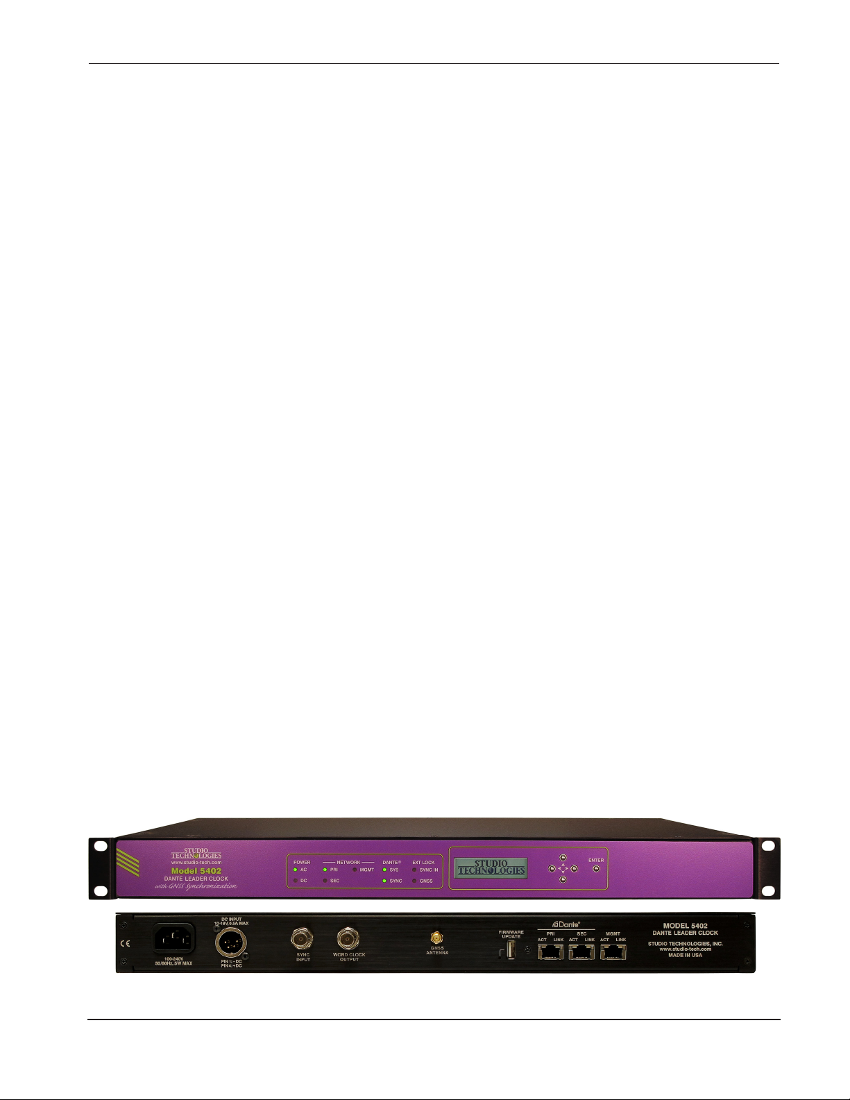
Model 5402
DANTE LEADER CLOCK WITH GNSS SYNCHRONIZATION
provides moisture protection, but the antenna should not
be left submerged in water. It’s possible that the antenna
will work from inside a building, such as next to a window
or beneath a skylight, but with reduced performance.
The antenna has an integral magnet such that it can self-
affix to a ferrous surface. It also has two mounting holes,
68 millimeters apart center-to-center, that are optimized
for use with M4 or number 8 screws. The antenna includes
a 5-meter (16.3-foot) nominal length of miniature RG174
(50 ohm) coaxial cable terminated with an SMA plug. The
plug must be securely affixed to the SMA jack on the Model
5402’s back panel. The cable must not be crushed and
sharp bends must be avoided. Do not secure the cable
using cable ties such that the cable’s mechanical charac-
teristics are changed.
It’s possible that the antenna’s cable can be extended using
a low-loss, 50-ohm nominal coaxial cable jumper assembly.
These are commercially available from a variety of sources.
The exact characteristics of an extension cable are difficult
to define, however minimizing signal loss is critical. Test-
ing the Model 5402 for proper GNSS reception with the
antenna and proposed cable extender in place is really the
only certain way of ensuring acceptable operation.
The Model 5402 can support the use of other multiband
GNSS antennas. Studio Technologies has tested several
other antennas and they performed very well. Refer to the
Technical Notes section of this guide for details.
Sync Input
An external synchronization source can be connected to
the Model 5402’s sync input BNC jack. Located on the back
panel, this input allows the Model 5402’s internal timing
to be “locked” to an external reference. In most cases,
utilizing the sync input won’t be necessary as the unit’s
GNSS receiver will typically provide an equal or better
timing reference.
Signals that are compatible with the Model 5402’s sync
input include word clock, bi-level video, tri-level video,
and 10 MHz sine wave. A configuration setting in the Sync
Input webpage defines what type of signal is going to be
connected. Another setting defines if a termination imped-
ance is applied to the sync input. Refer to the Specifications
section of this guide for the general characteristics required
of acceptable external sync signals.
A connected word clock signal must be a square wave with
a rate that matches the Dante sample rate as defined in the
Dante Controller application. The rate can be 44.1, 48, 88.2,
96, 176.4, or 192 kHz. If termination has been enabled for
the sync input when it has been configured for word clock
an impedance of 75 ohms will be applied.
A source of bi-level or tri-level video can also be connected
to the sync input. Circuitry within the Model 5402 will de-
code many of the common video rates and formats, allow-
ing them to serve as a timing reference. Refer to Appendix
A, located at the end of this guide, for a list of compatible
rates and formats. If the sync input is configured for video
and termination has been enabled an impedance of 75
ohms will be applied.
A source of 10 MHz sine wave can be connected to the
Model 5402’s sync input. This type of signal is commonly
used as a timing reference in industrial and instrumenta-
tion applications. An impedance of 50 ohms will be applied
to the sync input if termination has been enabled and the
source is selected for 10 MHz.
Word Clock Output
A word clock output signal is provided for use by other
devices that want to be “timed” from the Model 5402.
Available by way of a BNC jack located on the back panel,
the square wave output has a frequency that matches the
unit’s configured Dante sample rate. Choices are 44.1, 48,
88.2, 96, 176.4, and 192 kHz. The exact frequency of the
word clock output is based on the timing reference that has
been selected for the Model 5402. If, for example, GNSS
was selected as the unit’s timing reference, then the word
clock output would be “locked” to it.
The source impedance of the word clock signal is 75 ohms
and its unterminated output level is 5 volts peak-to-peak
(Vpp). When externally terminated with a 75 ohm load the
word clock output level will drop to 2.5 Vpp.
Ethernet Connections
The Model 5402 provides three Gigabit Ethernet (GigE)
ports for flexibility and compatibility with many networking
implementations. Two ports are provided for interconnec-
tions with one or two local area networks (LANs) associated
with Dante audio-over-IP networking schemes. They are
labeled as PRI (primary) and SEC (secondary). The third
Ethernet port, labeled MGMT, can be used to access the
Model 5402 management resources. An internal web server
function supports the Model 5402’s management port’s
webpages. These webpages are used for configuration,
monitoring, and maintenance of Model 5402 operation.
Refer to Figure 3 for an overview of the Model 5402’s three
Ethernet ports and how they can operate.
Using the Dante Controller application, the three Eth-
ernet ports can be configured to operate in one of four
modes: Switched, Redundant, Switched+Mgmt, or
Redundant+Mgmt. If configured for either the Switched
or Redundant modes the management webpages are ac-
cessed by way of the management Ethernet port. When
configured for the Switched+Mgmt mode the management

Issue 3, August 2021 Model 5402 User Guide
Page 10 Studio Technologies, Inc.
Model 5402
DANTE LEADER CLOCK WITH GNSS SYNCHRONIZATION
webpages are accessed by way of either the primary
or secondary Ethernet ports. When configured for the
Redundant+Mgmt mode the management webpages are
accessed using an Ethernet connection made to the pri-
mary Ethernet port.
By providing three Ethernet ports and four configuration
modes, the Model 5402 allows support for virtually all
facilities, including those that utilize separate networks
for Dante audio transport and equipment management.
In this way, “production” networks that support transport
of audio signals by way of a single LAN (Switched mode)
or two LANs (Redundant mode) can be separate from an
engineering network that is used by technical personnel for
configuring and maintaining a facility or “plant.”
Connections to the three Ethernet interfaces are made by
way of standard RJ45 jacks that are located on the back
of the Model 5402’s enclosure. The Ethernet interfaces
support auto MDI/MDI-X so that crossover cables are not
required. Refer to Appendix B, located at the end of this
guide, for examples of how the Model 5402’s three Eth-
ernet interfaces might be utilized. It’s difficult to conceive
of a network environment that the unit wouldn’t be able to
effectively support.
Dante Port Connections
At least one 1000BASE-T (GigE) Ethernet connection is
required for Model 5402 Dante operation. It should be con-
nected to the primary RJ45 jack. A second 1000BASE-T
(GigE) connection can be made to the secondary RJ45
jack if Redundant Dante is desired. For this functionality
to be active the Model 5402’s network configuration must
be set for the Redundant or Redundant+Mgmt mode within
the Dante Controller software application. While technically
100BASE-TX (100 Mb/s) Ethernet can also be used for
these Dante connections, it is not optimal. Additionally, it’s
important to note that 10BASE-T (10 Mb/s) Ethernet con-
nections are not sufficient.
When configured in Dante Controller for the Switched or
Switched+Mgmt modes the Model 5402’s Dante secondary
Ethernet connection can also be used as a “loop through”
port such as would be provided by an Ethernet switch.
Switched mode is the default setting but using the Dante
secondary port in this manner for applications other than
troubleshooting or “looping” to access the Model 5402’s
management port is not recommended. It will function
reliably but “daisy chaining” Ethernet signals can limit flex-
ibility and present a failure point; it’s optimal if each Dante
Ethernet interface connects directly to a separate port on
an Ethernet switch.
Management Port Connection
If required by the needs of an application, the management
webpages can be accessed using an Ethernet signal con-
nected to the Model 5402’s management Ethernet port.
This requires that the network mode in Dante Controller be
configured for Switched or Redundant. It’s recommended
that a 1000BASE-T (GigE) connection be made but a
100BASE-TX (100 Mb/s) connection is sufficient. (GigE
will provide the best performance and it’s assumed that all
contemporary applications will support it.)
Access to the Model 5402’s management webpages can
also be obtained using the same network connection or
connections that are being used for Dante audio. This
requires that the network mode in Dante Controller be con-
figured for Switched+Mgmt or Redundant+Mgmt. Appendix
B provides example of how these network scenarios can
easily be implemented.
Connecting Power
The Model 5402 requires a source of AC mains or nominal
12 volts DC for operation. Either source can be connected
with the same result. Both can also be simultaneously con-
nected if a redundant (backup) power scheme is desired.
Connecting AC Mains Power
The Model 5402 can operate directly from AC mains power
of 100 to 240 volts, 50/60 Hz, 5 watts maximum. As a “uni-
versal mains input” device there are no switches to set or
jumpers to install. A 3-pin IEC 320 C14 inlet connector on
the back panel mates with a detachable mains cord set.
All units are supplied from the factory with an AC mains cord
that has a North-American (NEMA 5-15L) standard plug on
one end and an IEC 320 C13 connector on the other end.
Dante Controller Network Model 5402 Ethernet Port
Switch Configuration Pri Sec Mgmt
Switched Dante Management
Redundant Dante Primary Dante Secondary Management
Switched+Mgmt Dante and Management Disabled
Redundant+Mgmt Dante Primary and Management Dante Secondary Disabled
Figure 3. Model 5402 Ethernet Port Configuration and Operation

Model 5402 User Guide Issue 3, August 2021
Studio Technologies, Inc. Page 11
Model 5402
DANTE LEADER CLOCK WITH GNSS SYNCHRONIZATION
Units intended for use in other destinations require that an
appropriate mains cord be obtained. The wire colors in the
mains cord should conform to the internationally recognized
color code and be terminated accordingly:
Connection Wire Color
Neutral (N) Light Blue
Line (L) Brown
Earth/Ground (E) Green/Yellow
Because the Model 5402 does not contain a power on/off
switch it will begin operation as soon as AC mains power
is connected.
Safety Warning: The Model 5402 does not contain an
AC mains disconnect switch. As such, the AC mains
cord plug serves as the disconnection device. Safety
considerations require that the plug and associated
inlet be easily accessible to allow rapid disconnection
of AC mains power should it prove necessary.
Connecting DC Power
The Model 5402 can also operate from a source of 10 to 18
volts DC. The current required from a 12 volts DC source
is 0.5 ampere (500 milliamperes) maximum. A 4-pin male
XLR connector, located on the unit’s back panel, is used
to connect the source of DC. Prepare a mating connector
(female) so that pin 1 is DC– and pin 4 is DC+. Pins 2
and 3 are not used and should remain unconnected. This
connector type and pinout have become a broadcast DC
power standard and should be familiar to many technical
personnel. Because the Model 5402 contains no power
on/off switch it will begin operation as soon as a DC power
source is connected.
As previously mentioned, both an AC mains source and a
DC source can be connected at the same time. If this is
the implementation then the AC mains source will always
power the Model 5402 with the DC source serving as a “hot
standby.” Only if the AC source fails will the unit draw power
from the DC source. This will occur automatically with no
interruption of Model 5402 operation. In this “standby”
mode (when an AC mains source is connected) the Model
5402 draws less than 110 microamperes (uA) from a 12
volts DC input.
Dante Configuration
For audio and timing to correctly pass from the Model 5402
requires that several Dante-related parameters be config-
ured. These configuration settings are stored in non-volatile
memory within the Model 5402’s Dante network interface
circuitry. Configuration will typically be done with the Dante
Controller software application, available for download free
of charge at audinate.com. Refer to Appendix C of the list
of the Model 5402’s Dante Controller default configura-
tion. Versions of Dante Controller are available to support
several operating systems.
The Model 5402’s Dante interface is compatible with the
Dante Domain Manager (DDM) software application. Refer
to DDM documentation, also available from Audinate, for
details on which Model 5402 and related parameters may
have to be configured.
Audio Routing
The Model 5402’s eight Dante transmitter (output) chan-
nels can be assigned to the desired Dante receiver (input)
channels on associated equipment. This will route the
eight channels associated with the tone generator func-
tion. Within Dante Controller a “subscription” is the term
used for routing a transmitter flow (a group of up to four
output channels) to a receiver flow (a group of up to four
input channels).
The Model 5402 uses a Brooklyn II module to implement its
Dante functionality. The number of transmitter flows associ-
ated with this module is 32 and, as such, typically no flow
limitation should occur. These flows can either be unicast,
multicast, or a combination of the two. Note, however, that
when AES67 mode is enabled in Dante Controller the Dante
transmitter (output) channels will only function in multicast;
unicast is not supported.
Unit and Channel Names
The Model 5402 has a default Dante device name of
ST-M5402- along with a unique suffix. The suffix identi-
fies the specific Model 5402 that is being configured. The
suffix’s actual alpha and/or numeric characters relate to
the MAC address of the unit’s Brooklyn II module. The
eight Dante transmitter (output) channels associated with
the tone outputs have default names of Tone 1 through
Tone 8. Using Dante Controller, the device and chan-
nel names can be revised as appropriate for a specific
application.
Device Configuration
The Model 5402 supports audio sample rates of 44.1, 48,
88.2, 96, 176.4, and 192 kHz with no pull-up/down options
available. The digital audio data is in the form of 24-bit
pulse-code modulation (PCM 24) samples. Clocking- and
latency-related parameters can be adjusted if required
in Dante Controller but the default values are typically
correct.
Network Configuration – Dante
As has been covered previously in this guide, the Model
5402 allows connection of one, two, or three Ethernet
signals using standard RJ45 jacks which are located on
the back panel. In many applications two of the jacks will

Issue 3, August 2021 Model 5402 User Guide
Page 12 Studio Technologies, Inc.
Model 5402
DANTE LEADER CLOCK WITH GNSS SYNCHRONIZATION
be used for Dante audio and the third for connecting to a
network designated for device management purposes. It’s
also possible to access the Model 5402’s management
webpages using the Dante Ethernet ports. The Model
5402’s Dante ports are labeled PRI and SEC indicating
that they are typically used for the primary and secondary
connections. The third Ethernet port is labeled MGMT, indi-
cating that it is intended for use accessing the management
webpages. How these three Ethernet ports function can
be selected in the Network Config – Switch Configuration
section of Dante Controller. The choices are Switched,
Redundant, Switched+Mgmt, and Redundant+Mgmt.
If Switched is selected then the Model 5402 can establish
one Dante audio connection with an Ethernet network. It
doesn’t matter which RJ45 jack is utilized, although for clar-
ity this would typically be the primary jack. The secondary
RJ45 jack can be used to interconnect with another piece
of networked equipment. The management Ethernet port
will be used to access the management webpages.
If the Model 5402’s Dante network is configured for
Switched ensure that only one of the two Dante RJ45 jacks
on the back panel is connected to the LAN associated with
the Dante network. If both of the Model 5402’s Dante RJ45
jacks are routed to ports on the same LAN this will typically
“crash” the network! (Although some of the latest/most-
advanced Ethernet switches will automatically detect and
prevent such a “network bridging” issue from occurring.)
If Switched+Mgmt is selected the same issues as discussed
in the previous two paragraphs would again apply. The
only difference is that the management webpages would
be accessed using the same Dante Ethernet port that is
being used to access the Dante network. The management
Ethernet port will be disabled.
If Redundant is selected then Dante’s Redundant net-
working capability will be enabled. In this case, separate
Ethernet LAN connections should be made to the Dante
primary and Dante secondary RJ45 jacks. Again, the Model
5402’s separate management Ethernet port will be used to
access the management webpages.
If Redundant+Mgmt is selected in Dante Controller then the
network connection made to the Dante primary Ethernet
port will also be used to access the management web-
pages. The Model 5402’s separate management port will
be disabled.
IP Addresses
When a Model 5402 has been configured for either the
Switched or Switched+Mgmt network mode a single Dante
IP address will be associated with the network connec-
tion that is made to either the Dante primary or the Dante
secondary RJ45 jack. If the network configuration has been
selected for Redundant or Redundant+Mgmt then separate
IP addresses and related network parameters will be as-
signed to the Dante primary and Dante secondary Ethernet
ports. No matter what network mode has been selected
the Model 5402 will always have a separate management
IP address.
Typically, the Model 5402’s Dante IP address or addresses
and related network parameters will be determined auto-
matically using DHCP or, if that’s not available, the link-local
network protocol. If desired, the Dante Controller applica-
tion does allow Dante IP addresses and related network
parameters to be manually set to a fixed (static) configu-
ration. While this is a more-involved process than simply
letting DHCP or link-local “do their thing,” if fixed addressing
is necessary then this capability is available.
Note that if the Model 5402’s network configuration has
been set for Redundant or Redundant+Mgmt then the
Dante primary and Dante secondary IP addresses and
related parameters can be independently configured. This
allows both Dante interfaces to be configured automatically,
both interfaces to be configured manually, or one interface
to be configured automatically and the other to be config-
ured manually.
By default, the Model 5402’s management IP address
and related network parameters will be determined auto-
matically using DHCP or link-local. A configuration option,
accessible using the front-panel display and associated
buttons or the management webpages, allows manual
control of the management IP address, subnet mask, and
gateway address values.
AES67 Configuration – AES67 Mode
Dante Controller allows a Model 5402 to be configured for
AES67 operation. This requires the AES67 mode to be set
for Enabled. As previously noted in this guide, if AES67
mode is enabled then PTPv2 will be utilized and the Dante
transmitter (output) channels will use multicast. The sample
rate will be fixed at 48 kHz.
Preferred Clock Source
By the very nature of its intended application, the Model
5402 will normally serve as the Leader Clock for all Dante-
enabled devices. The unit has the ability to communicate
with the Dante network, selecting itself as the Preferred
Leader and causing the Enabled Sync to External func-
tion to be enabled. The status of these two parameters
can be observed using the Clock Status function in Dante
Controller.
Settings accessible using the Model 5402’s management
webpages allow extensive changes to the clock configura-
tion. These are provided for use when troubleshooting or

Model 5402 User Guide Issue 3, August 2021
Studio Technologies, Inc. Page 13
Model 5402
DANTE LEADER CLOCK WITH GNSS SYNCHRONIZATION
addressing special applications. In most cases, the Model
5402’s default settings would be appropriate and should
be utilized.
Model 5402 Configuration
Many Model 5402 Dante Leader Clock operating param-
eters can be configured using the management system’s
webpages that are provided by way of one of the unit’s Eth-
ernet ports. The specific port utilized for management will
depend on the network configuration that is selected using
the Dante Controller application. A standard web browser
is all that is required to utilize the menu webpages.
Several key network configuration parameters can also
be viewed and revised using the Model 5402’s front-panel
graphics display and associated pushbutton switches.
Refer to Appendix D for details on which parameters can
be revised in this manner.
Management IP Address
It’s easy to identify the Model 5402’s management IP ad-
dress by way of the front-panel display. If the screen saver
function is active, as it will be in most situations, one of the
six pages that will automatically display will show the cur-
rent management IP address. As such, a user can simply
observe the sequencing menu pages and watch for the
one that displays the current management IP address. If
it’s desired that the current management IP address be
continuously displayed then the Enter pushbutton switch
on the front panel should be pressed. This will stop the
screen saver function and cause the current management
IP address to display. It will also allow the various menu
pages to be accessed using the up, down, left, and right
pushbutton switches. Simultaneously pressing the left and
right arrow buttons will cause the screen saver mode to
begin again. The screen saver mode will also automatically
start two minutes after the last press of any of the front-
panel pushbutton switches.
How the management Ethernet port obtains its IP address
will depend on the management interface configuration set-
ting. The default method is automatic so the Model 5402’s
management port will first try to obtain an IP address using
DHCP. If that is not successful an IP address will be as-
signed using the link-local protocol. An address of 169.254.
x.x will indicate that an IPv4 address was established using
link-local. The Model 5402 may also have been configured
to use a manual (fixed or static) IP address. The front-panel
display and associated pushbuttons, or the Model 5402’s
management webpages, can be used to review and/or
make changes to the management IP address and related
parameters.
Accessing the Management
Webpages
To access the Model 5402’s home webpage, type the unit’s
management IP address into a browser’s search bar. (It’s
possible that some browsers may require including the text
http:// followed by the IP address.) Of course, the computer
associated with the browser must be on the same LAN and
subnet as the Model 5402.

Issue 3, August 2021 Model 5402 User Guide
Page 14 Studio Technologies, Inc.
Model 5402
DANTE LEADER CLOCK WITH GNSS SYNCHRONIZATION
Home Menu
Once the Model 5402 menu system has been accessed the Home webpage will appear. It provides seven display-only
fields along with a link to the Login menu webpage. The fields are similar to those provided in the Main menu configura-
tion webpage. The current clock source field will display which timing source is actively being utilized by the Model 5402.
The GNSS status field will indicate the current condition of the Model 5402’s GNSS (satellite) receiver. The Sync Input
status field displays the current operating condition of the sync input whose BNC jack is located on the unit’s back panel.
The four Dante sync status fields will display the role that the Model 5402 is actively playing as PTPv1 and PTPv2 timing
resources for the devices connected to the associated network or networks. Details about these fields are provided in
the Main menu paragraphs found later in this section.

Model 5402 User Guide Issue 3, August 2021
Studio Technologies, Inc. Page 15
Model 5402
DANTE LEADER CLOCK WITH GNSS SYNCHRONIZATION
Login Menu
From the Home webpage click on the Login tab to access the Login webpage. Entry of a valid user name and password
is required to access the additional configuration menus. The Model 5402 doesn’t incorporate a sophisticated security
implementation. The user name and password, as well as the underlying software, is intended to keep “honest” people
from making unauthorized changes to the configuration of the Model 5402. It is not intended as a sophisticated, rigorous
security system.
Should the applicable user name and/or password be misplaced, refer to the Technical Notes section and/or Appendix
G of this guide for a recovery method.
User Name: Enter the Model 5402’s user name into this
field. It is case sensitive. The default user name is guest.
If both the default user name and the default password are
active then the user name will display in this field.
Password: Enter the Model 5402’s password into this field.
It is case sensitive. The default password is guest. If both
the default user name and the default password are active
then the password will display in this field.
Log In Button: Click on the Log In button to submit the
entered user name and password. If the correct entries
have been made the Main menu webpage will display. If
an incorrect user name and/or password is entered then a
login failed message will be displayed.

Issue 3, August 2021 Model 5402 User Guide
Page 16 Studio Technologies, Inc.
Model 5402
DANTE LEADER CLOCK WITH GNSS SYNCHRONIZATION
Main Menu
Once the correct user name and password have been submitted the Main menu webpage will be displayed. This menu
provides the ability to select three important operating parameters as well as displaying eight key real-time conditions. In
addition, the menu system allows direct access to other menu webpages.
Main Clock Source: This is a configurable field with four
choices: Internal, GNSS, Sync Input, and Dante.
This setting determines which source will be the main
(normal) timing source that is used by the Model 5402’s
circuitry as its own “Leader” timing reference. This is the
clock source that will be used by the Model 5402’s PTPv1
and PTPv2 servers that are critical to the Model 5402’s
support of related Dante devices. When Internal is selected
the Model 5402’s temperature-stabilized, high-performance
crystal oscillator is utilized. This will provide excellent tim-
ing accuracy and consistent long-term performance. This
source is far superior to that provided by other standard
Dante devices. This is the correct choice if GNSS is not go-
ing to be utilized or a high-quality external reference signal
is not going to be connected to the sync input.
When GNSS is selected the timing reference that is derived
from the selected satellite constellation or constellations
will be used. This would be, assuming that a solid GNSS
“lock” can be established, the most accurate and consistent
timing source. It’s expected that GNSS will be selected in
most Model 5402 applications.
When Sync Input is selected the Model 5402’s sync input
function will be utilized. Using a BNC jack, located on the
Model 5402’s back panel, an external source of word clock,
video reference, or 10 MHz sine wave can be connected.
Circuitry within the Model 5402 will “lock” (synchronize)
the internal timing signals to the externally provided refer-
ence signal.
Selecting Dante will instruct the Model 5402 to use the clock
signal provided by its Dante interface circuitry as its refer-
ence timing source. The Dante interface circuitry will either
use its internal crystal oscillator or synchronize to another
Dante device on the associated network. The actual clock
source used by the Model 5402’s Dante interface will de-
pend on a setting in the Dante Controller application.
The Model 5402 includes the choice of Dante as the main
clock source only for trouble-shooting or other factory-
directed activities. It’s not expected that this selection will
ever be used during normal Model 5402 operation. By
selecting Dante the excellent timing performance that can
be provided by the GNSS receiver, the sync input, or the
internal oscillator would not be utilized.
Failover Clock Source: This is a configurable field with
two choices: Internal and Dante.
This configuration choice selects which timing source will be
used should the Model 5402’s selected main clock source

Model 5402 User Guide Issue 3, August 2021
Studio Technologies, Inc. Page 17
Model 5402
DANTE LEADER CLOCK WITH GNSS SYNCHRONIZATION
become unavailable. Specifically, the failover source will
be used if a GNSS lock can’t be obtained or a valid sync
source is not connected to the sync input. If Internal is
selected then the unit’s crystal oscillator will be utilized
as the Leader clock source should a valid GNSS or sync
input signal not be available. If Dante is selected then the
failover source will be the timing signal derived from the
Model 5402’s Dante interface.
From a performance standpoint it’s preferable to select
Internal. This ensures that the best clock performance
can be obtained should the failover condition be active.
However, selecting Dante would allow an interesting, albeit
obscure, alerting feature to become active. In the Dante
Controller application, a device such as the Model 5402
that has been selected as the Preferred Leader with an
external source allowed will have an error condition occur if
the Model 5402’s Dante interface doesn’t detect an external
reference being applied. Losing the external reference is
what the Model 5402’s circuitry will do should failover be
activated and Dante selected as the failover source. In this
way, a Dante network user could be alerted to a clocking
issue should the Model 5402 lose its important GNSS or
external sync input source.
However, having an error condition reported in the Dante
Controller application is probably not terribly important. The
Dante SYNC LED, located on the Model 5402’s front panel,
will also offer a clear indication of a loss of a valid GNSS
or external sync input signal. This LED will typically slowly
flash green when the Model 5402 is functioning correctly as
the Leader clock for the Dante network. However, should
the unit be configured to use GNSS or an external sync
input signal and a valid one is not present, the SYNC LED
will flash orange to indicate this loss of lock and that the
failover source is in use. In addition, the display will provide
a text indication of this condition.
Force Preferred Leader: This is a configurable field with
two choices: Disabled and Enabled.
This function impacts how the Model 5402 will control a
Dante network’s selection of which device is going to serve
as the Leader clock. As the main reason for the Model
5402’s existence is to serve as a Leader clock, in most ap-
plications the unit should be serving in that role. By forcing
the Model 5402 to be a Preferred Leader clock it helps to
ensure optimal Dante network operation. By enabling this
configuration, users of the Dante Controller application
will not be able to accidentally disable the Model 5402
as a Preferred Leader. One can observe exactly what is
meant by the term Force Preferred Leader by unchecking
the Model 5402’s Preferred Leader check box in Dante
Controller. After a short interval the box will automatically
return to the enabled (checked) state.
How the Model 5402 handles forcing the Dante network to
be a Preferred Leader clock and, if applicable, automati-
cally supporting an external clock input is not trivial. This
ability to control Dante network operation is part of the
unit’s “secret sauce.” If the Model 5402’s clock source is
configured for Dante then the Model 5402 will force off
(uncheck) the Enable Sync to External selection in Dante
Controller. If the Model 5402’s main clock source is con-
figured for Internal, GNSS, or Sync Input then the Model
5402 will force on (check) the Enable Sync to External
configuration in Dante Controller. This will apply as long
as this specific Model 5402 is acting as Primary Leader,
Leader, or AES67 Leader.
Submit: A Submit button is located below the Force Pre-
ferred Leader field. For any changes made to the three
configurable fields on the Main menu webpage to be saved
and acted upon the Submit button must be pressed.
Current Clock Source: This is a display-only field with
choices of Internal, Internal (Failover Active), GNSS, Sync
Input, Dante, and Dante (Failover Active).
The text Failover Active will display in red as a warning of
an abnormal condition that warrants intervention. The cur-
rent clock source field can also display --- which indicates
a major hardware error and would warrant contacting the
factory.
When Internal is displayed it indicates that the Model 5402’s
internal temperature-stabilized oscillator is being used as
its timing reference. When Internal (Failover Active) is
displayed an abnormal condition is occurring. In this case,
the Model 5402 has been configured to use either GNSS
or external sync signal as the main clock source but a valid
one is not available; it is using its internal temperature-sta-
bilized oscillator as the failover timing reference. If GNSS
is displayed then the Model 5402 is using a timing signal
derived from the selected satellite constellation(s). If Sync
Input is displayed this indicates that an external timing
reference signal is connected to the sync input BNC jack
on the Model 5402’s back panel and it is being used as the
main clock source. If Dante is displayed this indicates that
the Model 5402 is using a timing reference derived from
its Dante network interface. This is not an invalid condition
but would typically only occur in a troubleshooting situation.
If Dante (Failover Active) is displayed an abnormal condi-
tion is occurring. In this case, the Model 5402 is using a
timing reference derived from its Dante network interface.
However, this is only occurring because the configured
main clock source is not currently available.
GNSS Status: This display-only field will show Locked
(Active), Locked (Standby), Locking, Unlocked, Antenna
Disconnected, Antenna Error, and Idle. If Locked (Active) is
displayed this indicates that the GNSS receiver is “locked”

Issue 3, August 2021 Model 5402 User Guide
Page 18 Studio Technologies, Inc.
Model 5402
DANTE LEADER CLOCK WITH GNSS SYNCHRONIZATION
to one or more satellites and the GNSS receiver is sup-
plying the unit’s timing reference. If Locked (Standby) is
displayed this indicates that the GNSS receiver is “locked,”
that the GNSS receiver is capable of serving as the unit’s
timing reference, but that it is not currently serving as the
unit’s main clock source. Locking means that the GNSS
receiver is in the process of locking (or attempting to lock)
to one or more of the possible satellite constellations. Un-
locked means that the GNSS is not currently locked to a
satellite constellation.
Antenna Disconnected would indicate that a GNSS antenna
is not currently connected. The Model 5402 detects this by
the absence of DC current being supplied by the circuitry
associated with the GNSS antenna SMA jack. Antenna
Error would typically indicate that too much DC current is
being supplied by the circuitry associated with the GNSS
antenna SMA jack. This could be indicative of a short circuit
in the antenna’s SMA plug or interconnecting cable. Idle
would indicate that the GNSS receiver is not selected to
be the main or failover clock source and is not currently
locked to a satellite.
Sync Input Status: This is a display-only field with choices
of Locked (Active), Locked (Standby), Unlocked, and Idle.
As a warning of an abnormal condition the text Unlocked
will display in the color red.
If Locked (Active) is displayed this indicates that a valid
signal is connected to the Model 5402’s sync input and is
serving as the unit’s timing reference. If Locked (Standby)
is displayed this indicates that a valid signal is connected
to the Model 5402’s sync input and while it is capable of
serving as the unit’s main timing reference it is not currently
serving as the main clock source.
If Unlocked is displayed it can be the result of several con-
ditions. It can display if a signal is connected to the Model
5402’s sync input but is not being recognized as a valid
timing reference. This can occur for multiple reasons. The
most common would be due to a configuration mismatch,
such as if a video reference is connected while the Model
5402’s sync input is configured to support a word clock
source. It might also indicate that a non-supported word
clock rate or an incompatible video reference is connected.
Unlocked could also be displayed if no signal is connected
to the sync input or if a connected signal is incorrectly termi-
nated, e.g., no termination applied when one is required or
if two terminations (“a double termination”) were present.
Idle will display if the sync input has not been selected as
the Model 5402’s main clock source and a valid source has
not been connected to the sync input. It simply indicates
that the sync input circuitry is not actively receiving an
external signal.
Primary Leader Clock: A display-only field will show the
MAC (media access control) address of the Dante net-
work’s currently active Primary Leader Clock. Displayed to
the right of the MAC address will be an additional piece of
information about what specific device is associated with
the displayed MAC address. If the MAC address is associ-
ated with this specific Model 5402 then the text will show
(This Device). If the MAC address is not for this specific
Model 5402 the text will show (Other Device).
A logical question to ask would be “so what is this Other
Device?” Unfortunately, the Model 5402’s firmware does
not have the ability to know more about a specific Primary
Leader Clock other than its MAC address. It can only de-
termine if the MAC address matches this specific Model
5402 or not. If the address doesn’t match then another
device has to be serving as the Primary Leader. The Dante
Controller may provide more detailed information about a
Dante network’s clocking. And network software or hard-
ware tools may allow a MAC address to be associated with
a specific device.
Note that the information provided in this field can be a bit
confusing, even to the writer of this guide. But for a network
maven it can be very useful when troubleshooting a com-
plex network timing issue. Reviewing several related issues
to Primary Leader Clock can be valuable. First of all, it’s
important to note that the reference to the word primary in
“Primary Leader Clock” has nothing to do with the primary
and secondary Ethernet interfaces! In this context Primary
Leader Clock refers to the device that all other devices in
a Dante network will follow.
In most cases, a Model 5402 will serve as the Primary
Leader Clock. But there is no requirement that it must play
this role. For example, a Model 5402 can serve as a Leader
Clock while following the timing provided by another device
that’s serving as the Primary Leader Clock. For another
example, one Model 5402 could serve as the Primary
Leader Clock while several other Model 5402 units serve
as PTP boundary clocks. These boundary clocks would,
by way of a unicast PTP message, synchronize with the
Primary Leader Clock. The boundary clocks could then
provide PTPv1 and PTPv2 functionality (using multicast)
with timing based on that derived from the Primary Leader
Clock. This method may be used to provide Dante device
timing across different subnets for complex or especially
large applications. For more in-depth control of these clock-
ing issues the Dante Domain Manager (DDM) software
application can be very useful.
Dante Sync Status: The Model 5402 can simultaneously
serve as a Leader clock for both Dante primary and Dante
secondary networks and is capable of supporting both
PTPv1 (IEEE 1588-2002) and PTPv2 (IEEE 1588-2008).

Model 5402 User Guide Issue 3, August 2021
Studio Technologies, Inc. Page 19
Model 5402
DANTE LEADER CLOCK WITH GNSS SYNCHRONIZATION
As such the unit is capable of acting as four independent
Leader clocks: PTPv1 for Dante primary, PTPv2 for Dante
primary, PTPv1 for Dante secondary, and PTPv2 for Dante
secondary. While the PTP processes are asymmetrical,
they do share the same internal timing reference. The
Model 5402 can also act as a PTPv1 and PTPv2 clock
follower but that would typically be utilized only for test
purposes. Standard and Redundant Dante (no AES67
support) uses PTPv1 and that is always enabled in the
Model 5402. AES67 utilizes PTPv2 clocking and if sup-
port for AES67 is desired within the Dante environment it
must be enabled using a configuration setting in the Dante
Controller application.
The Model 5402’s Main menu has four fields that display
the real-time sync status of the PTPv1 and PTPv2 functions
for the Dante primary and Dante secondary interfaces.
If the network configuration in Dante Controller for this
specific Model 5402 has been selected for Switched or
Switched+Mgmt the clocking status of the Dante primary
interface will be displayed. In this situation, the Dante
primary PTPv1 interface will show Leader, Follower, Link
Down, or Error (with the latter showing in red text). If AES67
support is enabled in Dante Controller then the same
choices will also be displayed in the primary PTPv2 field.
If AES67 support is not enabled then Disabled will show
in the primary PTPv2 field. Since Dante secondary is not
enabled then the secondary PTPv1 and secondary PTPv2
fields will show Disabled.
If the Model 5402’s network configuration has been se-
lected for Redundant or Redundant+Mgmt then both the
primary PTPv1 and secondary PTPv1 sync status fields
will display their respective sync status. They will show
the same choices as described above: Leader, Follower,
Link Down, or Error (with the latter showing in red text).
If AES67 support is enabled in Dante Controller then the
same choices will also be displayed in the primary PTPv2
and secondary PTPv2 fields. If AES67 support is not en-
abled then Disabled will show in both the primary PTPv2
and secondary PTPv2 fields.
Should Leader be displayed in a specific field it would indi-
cates that this specific Model 5402 is acting as the Leader
clock for the Dante network and clock function associated
with that field. If Follower is displayed this indicates that
this specific Model 5402 is obtaining its timing reference
from another Dante device on the network. This would be
the current display if this specific Model 5402 was serving
as a “hot” standby Dante Leader clock.
If Link Down is displayed this will indicate that a valid
Ethernet connection has not been made to the RJ45 jack
associated with that field’s Model 5402’s Ethernet interface.
A display of Error would indicate that this specific Model
5402 is having a permanent or temporary issue with its
internal circuitry. There may be occasions where Error
would display for a few seconds while Model 5402 circuitry
first becomes active.

Issue 3, August 2021 Model 5402 User Guide
Page 20 Studio Technologies, Inc.
Model 5402
DANTE LEADER CLOCK WITH GNSS SYNCHRONIZATION
GNSS Menu
The GNSS menu has a number of parameters that all relate to the Model 5402’s GNSS receiver function. The first seven
fields are display-only and show various conditions that are reported by the GNSS receiver. The last five parameters are
used to configure which satellite constellations will be utilized by the GNSS receiver.
Lock Status: This display-only field will show Locked,
Locking, or Unlocked. Locked means that the GNSS re-
ceiver is actively receiving a timing signal from one or more
of the possible satellite constellations. Locking means that
the GNSS receiver is in the process of locking (or attempt-
ing to lock) to one or more of the possible satellite constel-
lations. Unlocked means that the GNSS is not locked to a
satellite constellation. Error would indicate a problem with
the Model 5402’s circuitry being able to communicate with
the GNSS receiver circuitry.
Antenna Status: This display-only field will show Con-
nected, Disconnected, or Error. Connected indicates that
DC current in the acceptable range is being drawn from
the antenna input. No DC current is being drawn from the
antenna input when Disconnected is displayed. Error would
be displayed if too much DC current is being drawn from the
antenna input. This would typically indicate a short circuit
associated with the SMA plug and cable that is used to link
the Model 5402 with the antenna.
Number of Satellites: This field shows the number sat-
ellites that the Model 5402’s GNSS receiver is currently
actively receiving. In theory only one satellite is required
for the Model 5402 to be able to establish an accurate tim-
ing reference. But clearly a higher number is better as it
gives the GNSS receiver more timing reference choices.
The greater the number of supported constellations will
also increase the possible number of satellites that can be
received. In addition, the performance of the connected
antenna will have a direct bearing on the number of satel-
lites that the receiver is “tracking.” This would not just be
related to the capabilities of the antenna itself, but also its
location, its “view” of the sky, and the length and type of
interconnecting cable.
Signal Strength: This display-only field shows the energy
that the Model 5402’s GNSS receiver input section is re-
ceiving from the antenna. The larger the number the better
the receiver is able to “lock” to satellites. This number will
typically only be useful when troubleshooting a Model 5402
issue with the factory.
Longitude: This field shows the Model 5402’s longitude, in
degrees, as is calculated by the unit’s GNSS receiver.
Latitude: This field shows the Model 5402’s latitude, in
degrees, as is calculated by the unit’s GNSS receiver.
Time to First Fix: This field shows the time, in seconds,
that the Model 5402’s GNSS receiver required to establish
Table of contents
Other Studio Technologies Clock manuals