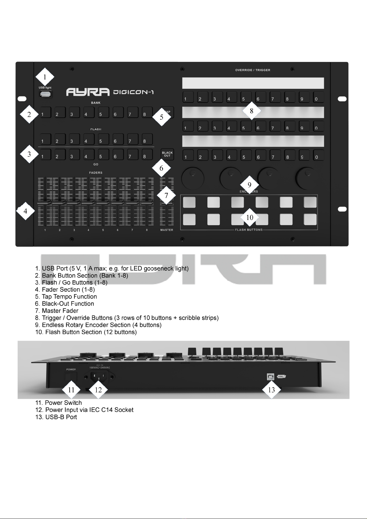
NAME MIDI code UTTON AND MESSAGE TYPE MIDI CHANNEL MIDI INDEX
Playback4 button A 26 BTN NOTE 4 OFF = 00, ON = 7F
Playback4 button B 27 BTN NOTE 1-8 OFF = 00, ON = 7F
Playback4 button C 28 BTN NOTE 1-8 OFF = 00, ON = 7F
Playback5 button A 29 BTN NOTE 5 OFF = 00, ON = 7F
Playback5 button B 2A BTN NOTE 1-8 OFF = 00, ON = 7F
Playback5 button C 2B BTN NOTE 1-8 OFF = 00, ON = 7F
Playback6 button A 2C BTN NOTE 6 OFF = 00, ON = 7F
Playback6 button B 2D BTN NOTE 1-8 OFF = 00, ON = 7F
Playback6 button C 2E BTN NOTE 1-8 OFF = 00, ON = 7F
Playback7 button A 2F BTN NOTE 7 OFF = 00, ON = 7F
Playback7 button B 30 BTN NOTE 1-8 OFF = 00, ON = 7F
Playback7 button C 31 BTN NOTE 1-8 OFF = 00, ON = 7F
Playback8 button A 32 BTN NOTE 8 OFF = 00, ON = 7F
Playback8 button B 33 BTN NOTE 1-8 OFF = 00, ON = 7F
Playback8 button C 34 BTN NOTE 1-8 OFF = 00, ON = 7F
Playback Fader 1 01 VR CC 1-8 00-7F
Playback Fader 2 02 VR CC 1-8 00-7F
Playback Fader 3 03 VR CC 1-8 00-7F
Playback Fader 4 04 VR CC 1-8 00-7F
Playback Fader 5 05 VR CC 1-8 00-7F
Playback Fader 6 06 VR CC 1-8 00-7F
Playback Fader 7 07 VR CC 1-8 00-7F
Playback Fader 8 08 VR CC 1-8 00-7F
TAP 57 BTN NOTE 1 OFF = 00, ON = 7F
Blackout 58 BTN NOTE 1 OFF = 00, ON = 7F
Master 09 VR CC 1 00-7F
button 1 35 BTN NOTE 1 OFF = 00, ON = 7F
button 2 36 BTN NOTE 1 OFF = 00, ON = 7F
button 3 37 BTN NOTE 1 OFF = 00, ON = 7F
button 4 38 BTN NOTE 1 OFF = 00, ON = 7F
button 5 39 BTN NOTE 1 OFF = 00, ON = 7F
button 6 3A BTN NOTE 1 OFF = 00, ON = 7F
button 7 3B BTN NOTE 1 OFF = 00, ON = 7F
button 8 3C BTN NOTE 1 OFF = 00, ON = 7F
button 9 3D BTN NOTE 1 OFF = 00, ON = 7F
button 10 3E BTN NOTE 1 OFF = 00, ON = 7F
button 11 3F BTN NOTE 1 OFF = 00, ON = 7F
button 12 40 BTN NOTE 1 OFF = 00, ON = 7F
button 13 41 BTN NOTE 1 OFF = 00, ON = 7F
button 14 42 BTN NOTE 1 OFF = 00, ON = 7F
button 15 43 BTN NOTE 1 OFF = 00, ON = 7F
button 16 44 BTN NOTE 1 OFF = 00, ON = 7F
button 17 45 BTN NOTE 1 OFF = 00, ON = 7F
button 18 46 BTN NOTE 1 OFF = 00, ON = 7F
button 19 47 BTN NOTE 1 OFF = 00, ON = 7F
button 20 48 BTN NOTE 1 OFF = 00, ON = 7F
button 21 49 BTN NOTE 1 OFF = 00, ON = 7F
The information in this user manual is subject to change at any time without notice.
Version: 1.0 Date of creation and author's initials: 02-12-2020 RV Revision date and author's initials: -