STUDIODUE Terra Plus RDM 1733 User manual

User manual for art. 1733 -1734 - 1735
Manuale d’uso per art. 1733 - 1734 - 1735
Terraplus
User manual for art. 1730 -1731 - 1732 - 1736
Manuale d’uso per art. 1730 -1731 - 1732 - 1736

2
rel. 03/19 • Studio Due
this page is intentionally left blank / questa pagina è stata intenzionalmente lasciata vuota

3rel. 03/19 • Studio Due
art. 4 PIN/XLR MF
(OPTIONAL)
INDOOR USE ONLY
art. 4 PIN/XLR MF male/female connectors
(optional)
art. 4 PIN/XLR MF connettori maschio/femmina
(opzionale)
these
CONNECTORS
are for INDOOR use
only
these
CONNECTORS
are IP67
questi connettori sono
solo per uso INTERNO questi connettori
sono IP67
,I\RXZDQWWRFRQQHFWWKH¿[WXUHVIRU
OUTDOOR use, you can make a new
cable utilizing the
art. 4 PIN-CONN M/F
The cable is not endowed with the
connectors kit
Se volete utilizzare gli apparecchi
all’ESTERNO, potete realizzare dei
nuovi cavi con
art. 4 PIN-CONN M/F
Il cavo non è incluso nel kit dei connettori
art. 4 PIN-CONN M/F
HQGRZHGZLWKWKH¿[WXUHLQFOXVRQHOO¶DSSDUHFFKLR
RSWLRQDORS]LRQDOH
!
WARNING
IMPORTANTE
3,1FRQQHFWRU&RQQHWWRUH3,1
,QWKLVFRQQHFWRU\RXFDQ¿QGWKH
NUMBER 4 or the GROUND sign. In questo connettore potete trovare il
NUMERO 4 o il simbolo della TERRA.
TERRA PLUS labelTERRA PLUS-T label

4
rel. 03/19 • Studio Due
INDEX
Page 5 - Physical / Dimensioni
Page 6 - Locking appliance during transport / Bloccaggio apparecchio durante il trasporto
Page 7 - Fixing of the formwork / Fissaggio della cassaforma
Page 8 - Safety informations / Informazioni di sicurezza
Page 9 - Introduction / Introduzione
Page 10 - Technical features / Caratteristiche tecniche
Page 12 - Example of connection DMX controller-fixtures / Esempio di collegamento centralina DMX-fari
Page 13 - Main supply connection / Collegamento fonte di alimentazione
Page 14 - DMX line connection / Collegamento alla linea DMX
Page 14 - DMX terminal line/ Terminale linea DMX
Page 15 - DRS functioning / Funzionamento del DRS
Page 16 - DRS menu list / Lista menu DRS
Page 17 - Tilt adjustment / Regolazione posizione tilt
Page 18 - DMX Listing / Lista dei canali DMX
Page 21 - CE standards / Certificazioni CE
Page 22 - Warranty / Garanzia

5rel. 03/19 • Studio Due
PHYSICAL / DIMENSIONI
200
Ø290
plastic
case
Ø200
262
Ø229
-2° +10°
motorized tilt adjustment
art.1733-1734-1735 only
art.
1733-1734-1735
only
m
a
n
u
a
l
p
a
n
1
8
0
°
IMPORTANT BEFORE MOUNTING / IMPORTANTE PRIMA DEL MONTAGGIO
PLASTIC CASE
DRAINAGE
ground level
xture
!
!be sure to create sucient
drainage around the plastic case

6
rel. 03/19 • Studio Due
TERRA PLUS RDM with Plastic Case (included)
IMPORTANT
!
DURING THE TRANSPORT / DURANTE IL TRASPORTO
DURING TRANSPORT, THE HEAD OF THE APPLIANCE MUST BE LOCKED BY THE TILT LIMIT IN THE POSITION +
10 ° OR -2 °.
OPERATE WITH THE DEDICATED DRS SETUP, MOVING THE HEAD IN ONE OF THESE POSITIONS.
DURANTE IL TRASPORTO, LA TESTA DELL’APPARECCHIO DEVE ESSERE BLOCCATA TRAMITE IL FINE CORSA
NELLA POSIZIONE +10° OPPURE -2°.
OPERARE CON IL DRS SETUP DEDICATO SPOSTANDO LA TESTA IN UNA DELLE DUE POSIZIONI.
TILT LIMIT +10°
FINE CORSA +10°
LIMIT SWITCH -2°
FINE CORSA -2°
+10° -2°
STOP
ONLY for version with TILT ADJUSTMENT - remove the label from the glass
ONLY for version with TILT ADJUSTMENT - remove the label from the glass

7rel. 03/19 • Studio Due
IMPORTANT
!INSTRUCTIONS FOR THE CORRECT APPLICATION OF THE FORMWORK OF THE TERRA PLUS
FIXTURES. ALL VERSIONS.
ISTRUZIONI PER LA CORRETTA POSA IN OPERA DELLA CASSAFORMA DEGLI APPARECCHI
TERRA PLUS. TUTTE LE VERSIONI.
Formwork /
Cassaforma
c)
Position (fit) and screw on the formwork the first aluminum
adjustment plate (p1).
In the opposite position fit and screw the second aluminum
adjustment plate (p2) as shown in the picture (a).
a)
(p1)
(p1) (p2)
The plates p1 and p2 positioned in this way, allow to cement
the formwork in the correct position with the finished instal-
lation level (f). See picture (c).
Le piastre p1 e p2 posizionate in questo modo, consentono
di cementare la cassaforma nella posizione corretta con il
livello finito di installazione (f). Vedi immagine (c).
finished installation level (f)
(c)
b) Insert the formwork in the hole created to house the appliance
so that the aluminum adjustment plates (p1 and p2) are at the
finished installation level (f) and in the correct position.
Posizionare la cassaforma nel foro creato per alloggiare l’ap-
parecchio in modo che le piastre di registro in alluminio (p1 e
p2) si trovino al livello finito di installazione (f) e in posizione
corretta.
Posizionare (inserire) e avvitare sulla cassaforma
il primo registro in alluminio di livello terra (p1).
Nella posizione opposta, fissare e avvitare la se-
conda piastra di registro in alluminio (p2) come
mostrato nella figura (a).
finished installation level (f)
d) Remove the plates p1 and p2. The formwork is now correctly
positioned.
Rimuovere le piastre p1 e p2. La cassaforma è ora posiziona-
ta in modo corretto
CORRECT FIXING OF THE FORMWORK - CORRETTO FISSAGGIO DELLA CASSAFORMA

8
rel. 03/19 • Studio Due
eng
WARNING
!SAFETY INFORMATION (service personnel)
READ ALL CAUTIONS AND WARNINGS PRIOR TO OPERATE THIS EQUIPMENT.
INSTRUCTION TO PREVENT INJURY OR DAMAGE DUE TO ELECTRIC SHOCK, FIRE, MECHANICAL HAZARDS,
DANGEROUS MATTERS.
•PROTECTION AGAINST FIRE
1) Maintain minimum distance of 0.1 meter from walls or any other type flammable surfaces.
2) Maintain minimum distance of 0,1 meter to lighted objects .
3) Replace fuses (if present) only with the specified type and rating.
4) Do not install the fixture close to heat sources. Do not lay the connection cable on the fixture when it is warm.
5) Fixture designed to be installed on normally flammable surfaces.
•PROTECTION AGAINST ELECTRIC SHOCK
1) This equipment must be earthed.
2) Class I equipment. The power supply cord includes a protective earthing conductor as part of the cord.
3) Disconnect power before servicing (service personnel).
•PROTECTION AGAINST MECHANICAL HAZARDS
1) Use secondary safety chain when fixing this equipment.
2) Equipment surface may reach temperature up to 75°C.
3) The protection screens and the lenses must be replaced with genuine parts only if they are visibly damaged and
their effectiveness has been reduced, for example, by cracks or deep scratches.
•PROTECTION AGAINST DANGEROUS MATTERS
At the end of its life, must be collected separately. It shouldn’t be thrown as urban waste and neither released in the
environment.
It must be collected from the nearest special waste collection point or consigned to your dealer that provides the servi-
ce. The incorrect waste disposal can damage the environment and the people for the presence of dangerous substan-
ces. Sanctions are provided for an unauthorized disposal.
F
INFORMAZIONI DI SICUREZZA (personale di servizio)
LEGGERE ATTENTAMENTE TUTTI GLI AVVERTIMENTI PRIMA DI COMPIERE QUALUNQUE OPERAZIONE SU QUESTO
APPARECCHIO. ISTRUZIONI PER PREVENIRE LESIONI O DANNI DOVUTI AL FUOCO, ALLE SCOSSE ELETTRICHE,
AI RISCHI MECCANICI ED A SOSTANZE PERICOLOSE.
•PROTEZIONE CONTRO IL FUOCO
1) Mantenere la distanza minima di 0.1 metri da pareti ed altre superfici infiammabili.
2) Mantenere la distanza minima di 0,1 metri dagli oggetti illuminati.
3) Sostituire i fusibili (se presenti) solo con altri dello stesso tipo e valore.
4) Non installare il faro vicino fonti di calore. Non appoggiare il cavo di connessione sul faro quando questo è caldo.
5) Questo apparecchio è adatto per il montaggio su superfici normalmente infiammabili.
•PROTEZIONE CONTRO SCOSSE ELETTRICHE
1) Questo apparecchio necessita di messa a terra.
2) Apparecchio di Classe I. Il conduttore di protezione deve far parte del cavo di alimentazione.
3) Disconnettere l’alimentazione prima di aprire l’apparecchio (personale di servizio).
•PROTEZIONE CONTRO RISCHI MECCANICI
1) Usare la catena di sicurezza supplementare quando installate il faro.
2) La temperatura dell’apparecchio può raggiungere 75°C.
3) Gli schermi di protezione e le lenti devono essere sostituiti sempre con ricambi originali
se sono visibilmente danneggiati e se la loro efficacia è stata ridotta, per esempio, da fessure o incisioni profonde.
IMPORTANTE
!
•PROTEZIONE CONTRO SOSTANZE PERICOLOSE
A fine vita è oggetto di raccolta separata, non gettare nei comuni cassonetti di rifiuti urbani, né tantomeno nell’am-
biente. Può essere consegnato presso gli appositi centri di raccolta differenziata predisposti dalle amministrazioni
comunali, oppure presso i rivenditori che forniscono questo servizio. Lo smaltimento errato può causare danni alle
persone e all’ambiente per la possibile presenza di sostanze pericolose. Sono previste sanzioni in caso di smaltimen-
to abusivo dei suddetti prodotti.
F
0,1 m
ita
0,1 m
IP67
IP67

9rel. 03/19 • Studio Due
WARNING
!
Check that the fixture has not been damaged during transport. If it has been damaged or it does not work,
address the seller. Whether the fixture has been shipped to you directly, please contact the shipping company.
Only the consignee (person or company) can claim for these damages.
INTRODUCTION
Thank you for using TERRA PLUS RDM, our inground LED lighting fixture with powerful LEDs, with IP67 rating protection and in
RGBW, WHITE BALANCE or MONOCHROMATIC light source.
• Available two versions: with STATIC OPTICS or with TILT ADJUSTMENT.
It is possible to adjust the TILT position of the fixture only for art. 1733 - 1734 - 1735.
The motorized tilt adjustment function (by dedicated DRS SETUP-T) allows you to position the light beam in the most appropriate
way, so it is not necessary to open the device that maintains the degree of protection IP67.
Manual Pan 180° and motorized Tilt adjustment -2° +10°. TERRA PLUS RDM series can be used to decorate columns, pillars, along
walkways, on patios, in steps, to highlight and to landscape details and key elements.
• Standard fixture colour finishing is grey.
To obtain the best performances and for a correct functioning of this unit for the years to come, we suggest you to read carefully this
manual before connecting or putting the fixture into use. By doing so you will gain experience with its commands and connections
and you will be easily able to use it.
YOUR REFERENCE
Always remember to give the serial number and to specify the model any time you address the seller for information or assistance.
BASIC KIT
• Projector
• n.2 connectors 4 pin male and female (without cable)
• User manual
• Studio Due warranty
• CE standards
INTRODUZIONE
Grazie per utilizzare TERRA PLUS RDM, il nostro apparecchio di illuminazione con potenti LED, protezione IP67 e sorgente luminosa
RGBW, WHITE BALANCE o MONOCROMATICA.
• Disponibili in due versioni: con OTTICA STATICA o con REGOLAZIONE TILT.
È possibile regolare la posizione TILT dell’apparecchio solo per l’art. 1733 - 1734 - 1735.
La funzione di regolazione inclinazione motorizzata (con DRS SETUP-T dedicato) consente di posizionare il fascio luminoso nel modo
più appropriato, senza aprire il dispositivo che mantiene così il grado di protezione IP67.
Pan manuale 180 ° e regolazione motorizzata Inclinazione -2 ° + 10 °. La serie TERRA PLUS RDM può essere utilizzata per decorare
colonne, pilastri, passaggi pedonali, nei cortili, per evidenziare passaggi e ai dettagli paesaggistici o elementi chiave.
• La finitura standard del colore dell’apparecchio è grigio.
Per ottenere il meglio delle prestazioni ed un corretto funzionamento negli anni di questa unità, Vi consigliamo di leggere
attentamente questo manuale prima di collegarla e metterla in uso. In questo modo acquisirete familiarità con i suoi comandi
e collegamenti affinché possiate utilizzarla facilmente.
VOSTRA REFERENZA
Citate sempre il numero del modello e di serie ogni volta che Vi rivolgete al vostro rivenditore per informazioni o assistenza.
CONFEZIONE BASE
• Proiettore
• n.2 connettori a 4 pin maschio e femmina (senza cavo)
• Manuale d’uso
• Garanzia Studio Due
• Dichiarazione CE
Controllate che l’apparecchio non abbia subito alcun danno durante il trasporto.
Se avesse subito dei danni o se non dovesse funzionare, rivolgetevi al vostro rivenditore.
Se l’apparecchio vi è stato spedito direttamente, rivolgetevi subito alla ditta di trasporto.
Solo il destinatario (la persona o ditta ricevente l’apparecchio) può reclamare per questo tipo di danni.
IMPORTANTE
!
eng
ita
version with TILT ADJUSTMENT
• Art. 1733 TERRA PLUS-T RDM RGBW;
• Art. 1734 TERRA PLUS-T RDM / WB;
• Art. 1735 TERRA PLUS-T RDM / M
version with STATIC OPTICS
• Art. 1730 TERRA PLUS RDM RGBW;
• Art. 1731 TERRA PLUS RDM / WB;
• Art. 1736 TERRA PLUS RDM / M
• Art. 1732 TERRA PLUS / M (plug-in)
versione con TILT ADJUSTMENT
• Art. 1733 TERRA PLUS-T RDM RGBW;
• Art. 1734 TERRA PLUS-T RDM / WB;
• Art. 1735 TERRA PLUS-T RDM / M
versione con OTTICA STATICA
• Art. 1730 TERRA PLUS RDM RGBW;
• Art. 1731 TERRA PLUS RDM / WB;
• Art. 1736 TERRA PLUS RDM / M
• Art. 1732 TERRA PLUS / M (plug-in)

10
rel. 03/19 • Studio Due
RGBW
Inground LED fixture with 12 powerful RGBW LEDs. IP67 rating protection.
Only for art. 1733 is possible to adjust the TILT position of the fixture. Manual Pan 180° and motorized Tilt adjustment -2° +10°.
The motorized tilt adjustment function (by dedicated DRS Setup) allows you to position the light beam in the most appropriate way,
so it is not necessary to open the device that maintains the degree of protection IP67.
TERRA PLUS RDM RGBW can be used to decorate columns, pillars, along walkways, on patios, in steps, to highlight and to landscape details and key
elements.
• Standard fixture colour finishing is grey.
ITEM FIXTURE [ KEY features ]
LEDs RGBW 12 RGBW
Total light power 40W
Lumen R 600, G 1100, B 170, W 1200
Optics 15° beam (38 mm lenses) - On request: medium and wide beam
Pan - Tilt art. 1733 only Manual Pan 180° - Motorized Tilt adjustment -2°... +10° by DRS Setup (needed)
Power consumption 45W - 0,2A@230V - PF0,9
Voltage range Universal 100 - 240Vac
Physical DxH: ø 290x200mm
Weight 5,5 Kg
Control Standard interface: RS-485, Protocol: RDM / DMX 512, Artnet by external converter
Connections Main Power: 3x1 cable
DMX INPUT and Tilt control: 4 Pin Male IP67 connector
DMX OUTPUT: 4 Pin Female IP67 connector
Setup RDM Control/configuration or individually by DRS (remote control device)
Dedicated DMX channel for white balance
DMX or Auto mode with Master-Slave function
Intelligent temperature control
Halogen simulation
CYM simulation
Flicker-free function
Smooth dimming function
DMX channels 10CH mode, 9CH mode, 5CH mode, 4CH mode, 3CH mode
200
Ø290
plastic
case
Ø200
262
Ø229
-2° +10°
motorized tilt adjustment
art. 1733-1734-1735 only
art.
1733-1734-1735
only
m
a
n
u
a
l
p
a
n
1
8
0
°
manual
pan 180° -2° + 10° motorized
tilt adjustment
dedicated DRS Setup for Tilt adjustment
RGBW
15°
OPTICS
medium
OPTICS
wide
OPTICS IP
67
LED RDM
TECHNICAL FEATURES / CARATTERISTICHE TECNICHE art. 1733 - 1730
version with motorized TILT ADJUSTMENT
• Art. 1733 TERRA PLUS-T RDM RGBW
version with STATIC OPTICS
• Art. 1730 TERRA PLUS RDM RGBW

11 rel. 03/19 • Studio Due
Inground LED fixture with powerful MONOCHROMATIC LEDs. IP67 rating protection.
Only for art. 1734 and 1735 is possible to adjust the TILT position of the fixture.
The motorized tilt adjustment function (by dedicated DRS Setup) allows you to position the light beam in the most appropriate way, so it is not
necessary to open the device that maintains the degree of protection IP67. Manual Pan 180° and motorized Tilt adjustment -2° +10°.
TERRA PLUS RDM /WB (White Balance) and TERRA PLUS RDM /M (Monochromatic) can be used to decorate columns, pillars, along walkways,
on patios, in steps, to highlight and to landscape details and key elements.
• Standard fixture colour finishing is grey
ITEM FIXTURE [ KEY features ]
LEDs Monochromatic 24 warm, neutral, cool white
On request: red, green, blue or amber
White Balance 12 Cool White + 12 Warm White
Total light power 40W
Lumen 6200 (4000K LEDs)
Optics 15° beam (38 mm lenses) - On request: medium and wide beam
Pan - Tilt art. 1734 and 1735 only Manual Pan 180° - Motorized Tilt adjustment -2°... +10° by DRS Setup (needed)
Power consumption 45W - 0,2A@230V - PF0,9
Voltage range Universal 100 - 240Vac
Physical DxH: ø 290x200mm
Weight 5,5 Kg
Control Standard interface: RS-485, Protocol: RDM / DMX 512, Artnet by external converter
Connections Main Power: 3x1 cable
DMX INPUT and Tilt control: 4 Pin Male IP67 connector
DMX OUTPUT: 4 Pin Female IP67 connector
Setup RDM Control/configuration or individually by DRS (remote control device)
Dedicated DMX channel for white balance
DMX or Auto mode with Master-Slave function
Intelligent temperature control
Halogen simulation
CYM simulation
Flicker-free function
Smooth dimming function
DMX channels Monochromatic 3CH mode, 1CH mode
White Balance 4CH mode, 2CH mode, 1CH mode
manual
pan 180° -2° + 10° motorized
tilt adjustment
2900K 6000K
WW W
warm neutral cool
BGR A
2900K 6000K
WW W
warm neutral cool
BGR A
15°
OPTICS
medium
OPTICS
wide
OPTICS IP
67
LED RDM
version with motorized TILT ADJUSTMENT
• Art. 1734-1735 TERRA PLUS-T RDM WB or M
version with STATIC OPTICS
• Art. 1731-1732-1736
TERRA PLUS RDM WB or M
TECHNICAL FEATURES / CARATTERISTICHE TECNICHE art. 1734 - 1735 - 1731 - 1732 - 1736

12
rel. 03/19 • Studio Due
EXAMPLE OF CONNECTION DMX CONTROLLER - FIXTURES / ESEMPIO DI COLLEGAMENTO CENTRALINA - APPARECCHI
DMX
¿[WXUH ¿[WXUH ¿[WXUH ¿[WXUH
TL
NORMAL
Address
set-up 9ch
&
Address
set-up 9ch
&
Address
set-up 9ch
&
Address
set-up 9ch
&
¿[WXUH ¿[WXUH ¿[WXUH
TL
MASTER/SLAVE
Set up = MASTER set-up = SLAVE set-up = SLAVE set-up = SLAVE
¿[WXUH
NORMAL AND MASTER/SLAVE FUNCTIONS / FUNZIONI NORMAL E MASTER/SLAVE
([DPSOH(VHPSLR
DMX
/DVW¿[WXUH
8OWLPRIDUR
7HUPLQDWLRQUHVLVWRU
7HUPLQDOHGLOLQHD
([DPSOH(VHPSLR
DMX
/DVW¿[WXUH
8OWLPRIDUR
7HUPLQDWLRQUHVLVWRU
7HUPLQDOHGLOLQHD
OLQHOLQHD
7HUPLQDWLRQUHVLVWRU
7HUPLQDOHGLOLQHD
OLQHOLQHD
'0;RXW '0;RXW
Connection controller-spot to
'0;RXWSXWRYHUPWORQJ
Collegamento centralina-spot ad una sola
OLQHDGLXVFLWD'0;OXQJDROWUHPW
/,1(!PWZLWKPLFURSKRQLFRUDXGLRFDEOH
/,1($!PWFRQFDYRPLFURIRQLFRRDXGLR
DMX
7HUPLQDWLRQUHVLVWRU
7HUPLQDOHGLOLQHD
([DPSOH(VHPSLR
SIGNALAMPLIFIER
AMPLIFICATORE
DI SEGNALE
/DVW¿[WXUH
8OWLPRIDUR
/DVW¿[WXUH
8OWLPRIDUR
DMX out
DMX out
TL=
Terminal Line
IRUH[DPSOH¿[WXUHVHWXSDWFKDQQHOV
TL
TL
TL
TL
MAINS
MAINS
MAINS
MAINS
13 rel. 03/19 • Studio Due
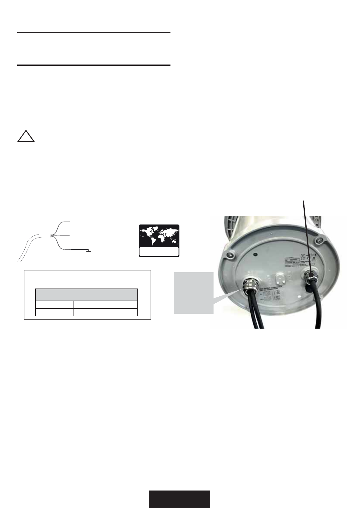
CONNECTION TO THE MAIN POWER / CONNESSIONE ALLA RETE ELETTRICA
This equipment must be earthed.
Class I equipment. The power supply cord includes a protective earthing conductor as part of the cord.
IMPORTANT: to ensure the IP67 protection rating, in case of replacement of the conductor cable, refer to the CONDUCTOR SIZE TABLE
Questo apparecchio necessita di messa a terra.
Apparecchio di Classe I. Il conduttore di protezione deve far parte del cavo di alimentazione.
IMPORTANTE: per garantire il grado di protezione IP67, in caso di sostituzione del cavo di alimentazione, fare riferimento alla
TABELLA SEZIONE CONDUTTORE.
eng
ita
WARNING
!
HIGH VOLTAGE!
Always disconnect the mains supply before access to the connection area.
ALTA TENSIONE!
Scollegare sempre l’alimentazione prima di aprire il vano dei collegamenti.
Main IN
Yellow/Green
Blue Neutral
100/240V.~ - 50/60Hz
Brown
UNIVERSAL MAIN VOLTAGE
100-240V.~ / 50-60Hz
MAIN IN
Ingresso rete
CONDUCTOR SIZES / SEZIONE CONDUTTORE
(length / lunghezza < 20mt.)
MAINS VOLTAGE CROSS SELECTIONAL AREAS
230V 3X1 mm2(minimum)
POWER INPUT/
INGRESSO ALIMENTAZIONE Ø 6 - 12mm NOT PRESENT in
PLUG IN version
NON PRESENTE
nella
versione PLUG IN
14
rel. 03/19 • Studio Due
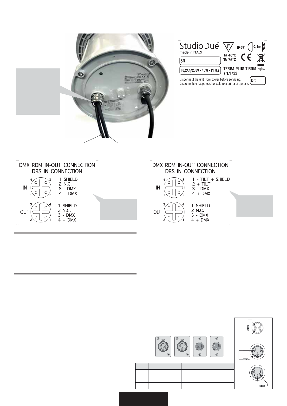
CONNECTION TO THE DMX LINE rear view / CONNESSIONE ALLA LINEA DMX vista posteriore
example of labels / esempi di etichette
DMX IN (male)
Ingresso DMX (maschio)
DMX OUT (female)
Uscita DMX (femmina)
ODEHOIRU¿[WXUH
with
STATIC OPTICS
ODEHOIRU¿[WXUH
with TILT
ADJUSTMENT
NOT PRESENT in
PLUG IN version
NON PRESENTE
nella
versione PLUG IN
DMX TERMINAL LINE
The wrong connection of the terminal line or its non-connection are probably the most frequent reasons of the lower DMX signal.
The terminator is a terminal resistor fitted at the end of the cable. (see pict. 1)
The terminal resistor should have the same value as the impedance of the connection cable (120 Ohm).
It is recommanded that all DMX 512 systems have the terminal resistor fitted in the end of DMX line.
TERMINALE LINEA DMX
L’incorretto o il mancato collegamento del terminale di linea è probabilmente la più comune causa del difettoso funzionamento
della linea DMX.
Il terminale di linea DMX consiste in una resistenza posta alla fine della linea. (vedere fig. 1)
La resistenza terminale dovrebbe avere lo stesso valore dell’impedenza del cavo di collegamento (120 Ohm).
E’ raccomandato per tutti i sistemi DMX 512, di inserire il teminale di linea nel connettore di uscita DMX dell’ultimo apparecchio
collegato.
eng
ita
Termination resistor
Terminale di linea
120 Ohm
PIN LANGISERIW
1SHIELD GROUND/RETURN/OV
2)DETREVNI,-(TNEMELPMOCATADROTCUDNOCRENNI
3INNER CONDUCTOR DATATRUE ( +, NON INVERTED)
DMX inputDMX output
Termination resistor
Terminale di linea
120 Ohm
Termination resistor
Terminale di linea
120 Ohm
DMX input
4
3
DMX output
pict. 1

15 rel. 03/19 • Studio Due
FUNZIONAMENTO DI BASE DEL DRS dedicato (DMX remote Setup-T) con REGOLAZIONE del TILT
Per effettuare la programmazione dei vari parametri di un apparecchio, è necessario procedere come segue:
• Disconnettere l’apparecchio da configurare da altri dispositivi DMX/RDM
• Collegare il cavo DMX dell’apparecchio da configurare, al programmatore DRS
• Accendere il programmatore DRS (premere qualsiasi pulsante) ed attendere che si visualizzi la scritta 8888
• Se il programmatore DRS individua un dispositivo DRS compatibile, visualizza per qualche istante la scritta
Conn e, successivamente, visualizza il nome dell’apparecchio e la relativa versione software
• Se il programmatore DRS non individua alcun dispositivo DRS compatibile o è presente qualche
malfunzionamento il display visualizzerà la scritta SCAn
• Una volta terminata la sequenza di riconoscimento, viene visualizzato il primo menu dell’apparecchio
• I pulsanti UP/DOWN permettono di scorrere la lista dei menu
• Il pulsante ENTER permettere di entrare in un menu o di confermare una opzione in caso di lampeggio del parametro
• Il pulsante ESC annulla una operazione o torna al livello di menu inferiore.
ita
Dedicated DRS (DMX Remote Setup-T) FUNCTIONING with TILT ADJUSTMENT
To make the set-up of the various fixture parameter, proceed as follow:
•Disconnect the fixture to set-up from the other DMX/RDM devices
• Connect the DMX cable of the fixture to the DRS commander
• Switch on the DRS commander (Press any button) and wait for the 8888 sign
• If the DRS commander detects a compatible DRS device, displays shortly the Conn written and afterwards,
displays the name of the fixture and its software version.
• If the DRS commander dont’ detects any compatible DRS device or is present any
malfunction, the display shows the SCAn written
• When the detection sequence is finished, the display shows the first menu
• The UP/DOWN buttons allow to scroll forward/backward the menu list
• The ENTER button allow to confirm the selected option (if the parameter is flashing)
• The ESC button allow to delete the operation and return to a previus menu level
eng
The DRS SETUP-T device
(for TERRA with TILT ADJUSTMENT)
can also be used for
TERRA with STATIC OPTIC
(ignore the TILT function)
Il dispositivo DRS SETUP-T
(per TERRA con REGOLAZIONE TILT)
può essere utilizzato anche per
TERRA con STATIC OPTIC
(ignorare la funzione TILT)

16
rel. 03/19 • Studio Due
Switching on the fixture you can see the model and the software version. For example:
All’accensione, viene visualizzato il modello di apparecchio e la versione software. Per esempio:
--> r - dr --> 1_01
than it’s shown the fist menu
poi viene visualizzato il primo menu
Address (Addr) Imposta l’indirizzo DMX
Set the DMX address
Auto Mode (ModE) Imposta la modalità DMX, SLAVE o MASTER
Set the DMX, SLAVE or MASTER mode
(no, SL, Pr01…Prxx)
Auto Speed (PrSP) Imposta la velocità di esecuzione dei giochi interni
Set the preset execution speed
( -400%…+400%)
N. Channels (nChn) Imposta il numero di canali DMX dell’apparecchio
Set the DMX channels of the fixture
(10, 9, 5, 4, 3)
Smooth Dimming (SMth) Imposta il tipo di interpolazione per la funzione smooth dimming
Set the interpolation type for the smooth dimming function
(OFF, Sd1, Sd2, Sd3)
Halogen Simulation (HALS) Imposta il funzionamento della modalità simulazione lampada alogena
Set the alogen simulation function mode
(OFF, Mod1, Mod2)
CYM Emulation (CYMS) Imposta l’apparecchio per funzionare come emulatore di sistema CYM o RGB
Set the fixture to work in CYM or RGB emulation system
(OFF -->RGBW, On -->CYM)
Flicker free function (FLcr) from 2.09 software version / dalla versione software 2.09
Select the value f1 .. f2
Selezionate il valore desidarato f1 .. f2
Test (tESt) Abilita il test dell’apparecchio ed esegue un programma di fabbrica per
verificarne il funzionamento
Enables the test of the fixture and execute a factory program to check
the right functioning
(OFF, On)
Reset (rSEt) Esegue un reset della parte elettronica
Execute a reset of the electronic section
Format (FrMt) Ripristina le impostazioni di fabbrica (Viene chiesta conferma)
Restore the factory setting (Require confirmation)
DRS MENU LIST / ELENCO MENU’ DRS

17 rel. 03/19 • Studio Due
-2° +10°
motorized tilt adjustment
art.1733-1734-1735 only
MAIN POWER
DMX LINE
collegare l’apparecchio
al DRS Setup dedicato
It is possible to adjust the TILT position of the
unit even without connecting it to the mains
power supply.
------------
E’ possibile la regolazione della posizione del
TILT dell’apparecchio anche senza collegare
quest’ultimo alla rete elettrica.
1
adjust the position of
the light beam
2
When the head of the appliance reaches the
limit switch, do not insist on the action.
Motor breakage risk.
Quando la testa dell’apparecchio raggiunge il
finecorsa, non insistere con l’azione.
Rischio di rottura del motore.
IMPORTANT
!
powered by battery
alimentato a batteria
connect the fixture
with the dedicated
DRS Setup
regolare la posizione
del fascio di luce
TILT ADJUSTMENT with dedicated DRS Setup /
REGOLAZIONE posizione TILT con DRS Setup dedicato
DRS Setup is required to adjust the TILT position of the unit. (-2° +10°)
It is possible to adjust the TILT position of the unit even without connecting it to the mains power supply.
However, we recommend that you select the program 001 (for example red program) in order to see the projected light source
and for the correct positioning.
È necessario utilizzare il DRS Setup dedicato, per regolare la posizione TILT dell’unità. (-2 ° + 10 °)
E’ possibile la regolazione della posizione del TILT dell’apparecchio anche senza collegare quest’ultimo alla rete elettrica.
Si consiglia comunque di selezionare il programma 001 (per esempio programma rosso) per poter vedere proiettato e per il
corretto posizionamento il fascio luminoso.
When the head of the appliance reaches the limit switch, do not insist on the action. Motor breakage risk.
Quando la testa dell’apparecchio raggiunge il finecorsa, non insistere con l’azione. Rischio di rottura del motore.
IMPORTANT
!

18
rel. 03/19 • Studio Due
DMX Channels list 10Ch / Lista dei canali DMX 10Ch
8 BIT FUNCTION 0 31 63 95 127 159 191 233 255
CH1 DIMMER
CH2 STROBE
FLASH 0,4Hz / 25Hz
2 -127
OPEN
0 - 1
RAINBOW - FLASH 0,4Hz / 25Hz
128 -255
CH3 LED FADE
TIME
FAST - 0,1 sec.
0 = CUT SLOW
25,5 sec.
LINEAR
CH4 RAINBOW
CH5 BALANCED
WHITE 0 - 15 NORMAL 16 - 255
WW CW
CH6 MACRO
0 - 15
no macro
neutral
white + CW
white CW
white mid
white WW
white + WW
white sodium
lamp sodium
lamp+
16 ....................................................................................................................................................................... 255
CH7 RED
CH8 GREEN
CH9 BLUE
CH10 WHITE
DMX Channels list 9Ch / Lista dei canali DMX 9Ch
8 BIT FUNCTION 0 31 63 95 127 159 191 233 255
CH1 RED
CH2 GREEN
CH3 BLUE
CH4 WHITE
CH5 STROBE
FLASH 0,4Hz / 25Hz
2 -127
OPEN
0 - 1
RAINBOW - FLASH 0,4Hz / 25Hz
128 -255
CH6 DIMMER
CH7 LED FADE
TIME
FAST - 0,1 sec.
0 = CUT SLOW
25,5 sec.
LINEAR
CH8 RAINBOW
CH9 BALANCED
WHITE 0 - 15 NORMAL 16 - 255
WW CW

19 rel. 03/19 • Studio Due
STUDIODUE light s.r.l.
str. Poggino, 100 - 01100 VITERBO ITALY - tel. +39 0761 352520 - fax +39 0761 352653
8 BIT FUNCTION 0 31 63 95 127 159 191 233 255
CH1 DIMMER
CH2 RED
CH3 GREEN
CH4 BLUE
CH5 WHITE
DMX Channels list 5Ch / Lista dei canali DMX 5Ch
DMX Channels list 4Ch / Lista dei canali DMX 4Ch
8 BIT FUNCTION 0 31 63 95 127 159 191 233 255
CH1 RED
CH2 GREEN
CH3 BLUE
CH4 WHITE
DMX Channels list 3Ch / Lista dei canali DMX 3Ch
8 BIT FUNCTION 0 31 63 95 127 159 191 233 255
CH1 RED
CH2 GREEN
CH3 BLUE

20
rel. 03/19 • Studio Due
8 BIT FUNCTION 0 31 63 95 127 159 191 233 255
CH1 DIMMER
CH2 STROBE
FLASH 0,4Hz / 25Hz
2 -127
OPEN
0 - 1
RAINBOW - FLASH 0,4Hz / 25Hz
128 -255
CH3 LED FADE
TIME
FAST - 0,1 sec.
0 = CUT SLOW
25,5 sec.
LINEAR
8 BIT FUNCTION 0 31 63 95 127 159 191 233 255
CH1 DIMMER
DMX Channels list 3Ch / Lista dei canali DMX 3Ch
MONOCHROMATIC / MONOCROMATICO
8 BIT FUNCTION 0 31 63 95 127 159 191 233 255
CH1 BALANCED
WHITE 0 - 15 NORMAL 16 - 255
WW CW
CH2 DIMMER
CH3 STROBE
FLASH 0,4Hz / 25Hz
2 -127
OPEN
0 - 1
RAINBOW - FLASH 0,4Hz / 25Hz
128 -255
CH4 LED FADE
TIME
FAST - 0,1 sec.
0 = CUT SLOW
25,5 sec.
LINEAR
8 BIT FUNCTION 0 31 63 95 127 159 191 233 255
CH1 BALANCED
WHITE 0 - 15 NORMAL 16 - 255
WW CW
8 BIT FUNCTION 0 31 63 95 127 159 191 233 255
CH1 BALANCED
WHITE 0 - 15 NORMAL 16 - 255
WW CW
CH2 DIMMER
DMX Channels list 4Ch / Lista dei canali DMX 4Ch
WHITE BALANCE
DMX Channels list 1Ch / Lista dei canali DMX 1Ch
DMX Channels list 2Ch / Lista dei canali DMX 2Ch
DMX Channels list 1Ch / Lista dei canali DMX 1Ch
This manual suits for next models
6
Table of contents
Other STUDIODUE Outdoor Light manuals


