C792US - 2006_11_REV-002
A
START
HERE
Warning: The Luminaire should only be used complete with its protective shield (cover)
IMPORTANT INSTRUCTIONS
t90 C
1m
F
A.C.N. 010 572 773
UL available L
U
R
1INSTALLATION
Should you experience any difficulty please contact your supplier.
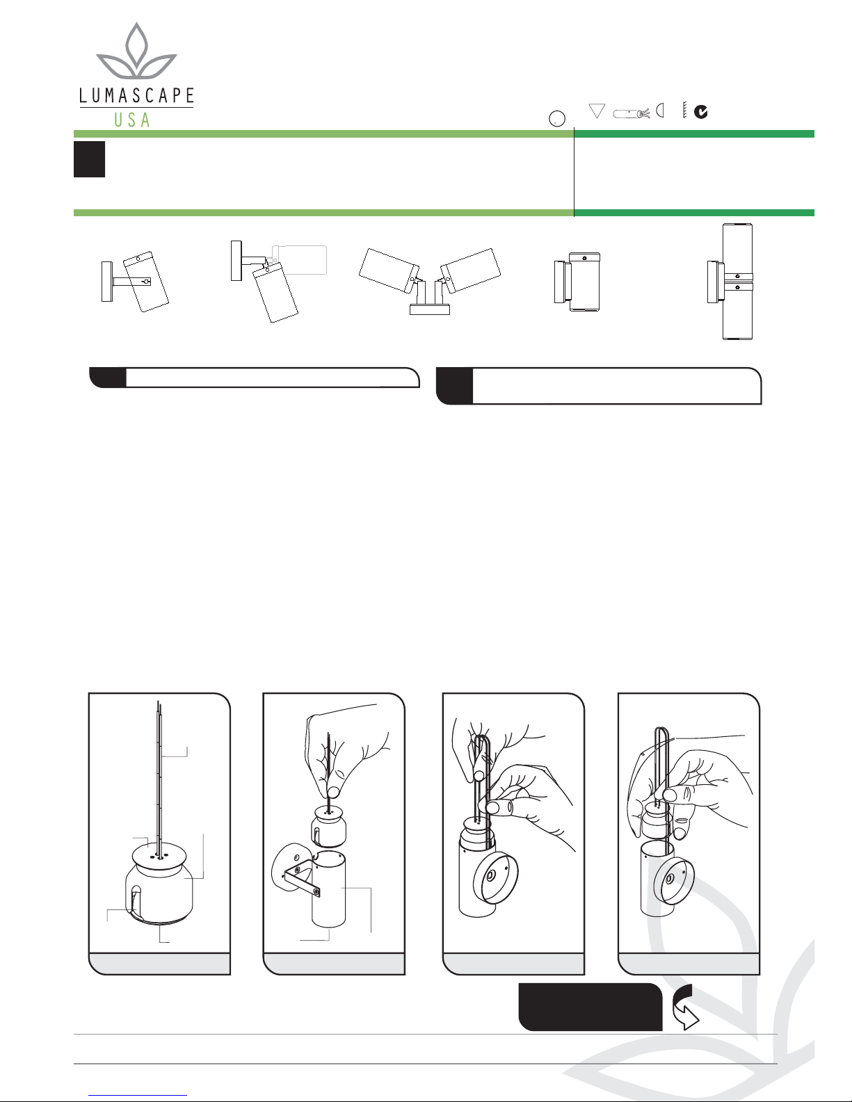
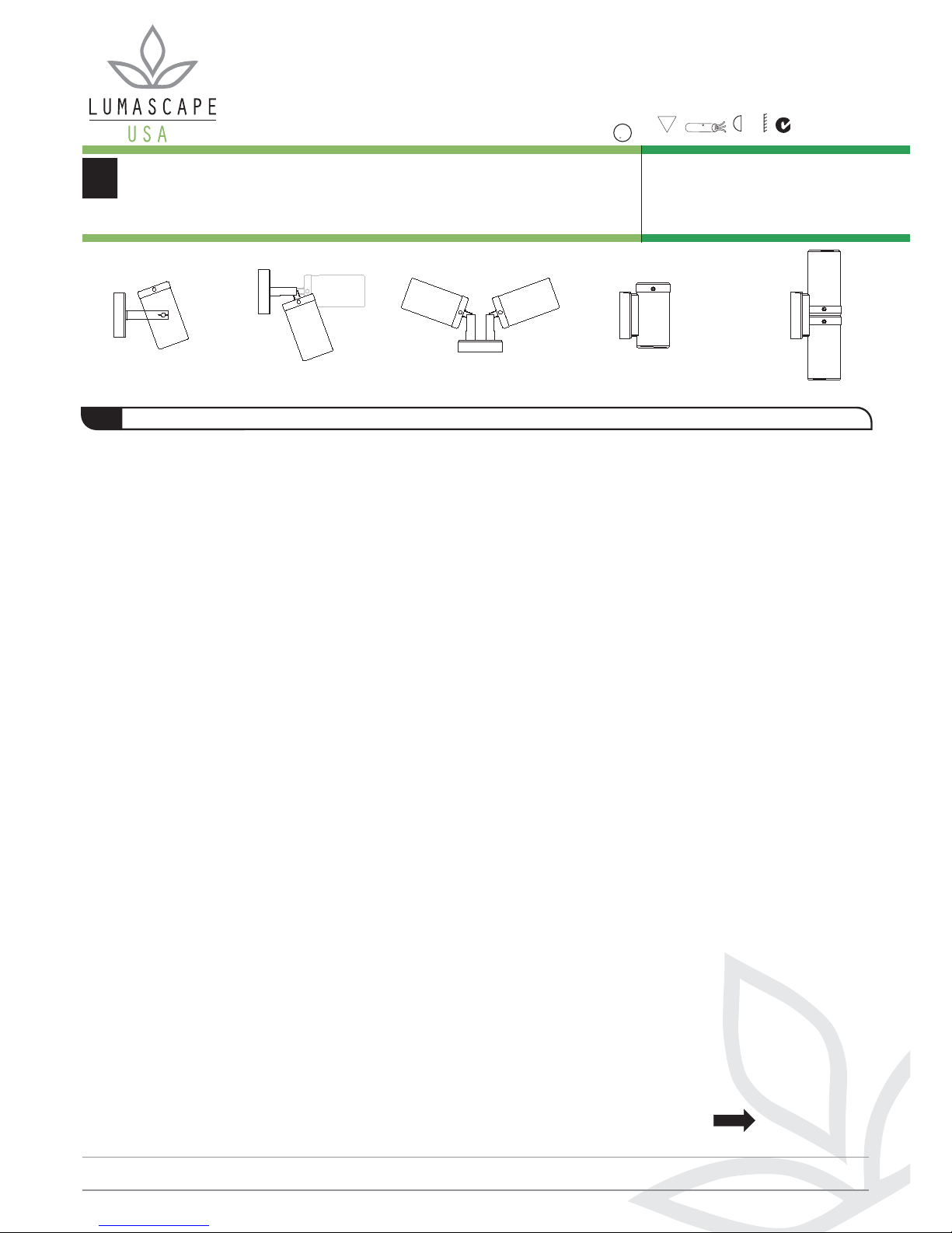
LS101A LS321A LS321-2A LS201A-3 LS121A-2
For Installation: LS101A, LS321A, LS321-2A, LS201-3, LS121A-2
1. Select a suitable 12 volt isolating type transformer and locate
centrally in relation to fixtures (Figure A).
2. Mark actual locations of fixtures to be installed. Calculate
voltage drop on each run of cable (refer voltage drop
section).
3. Lay cable from transformer to each fixture (refer voltage drop
section).
4. Take supplied rubber gasket for the backing plate and peel
from backing paper.
5. When handling self adhesive gasket, try to sit the ring on the
tip of one finger allowing the seal to hold its own shape.
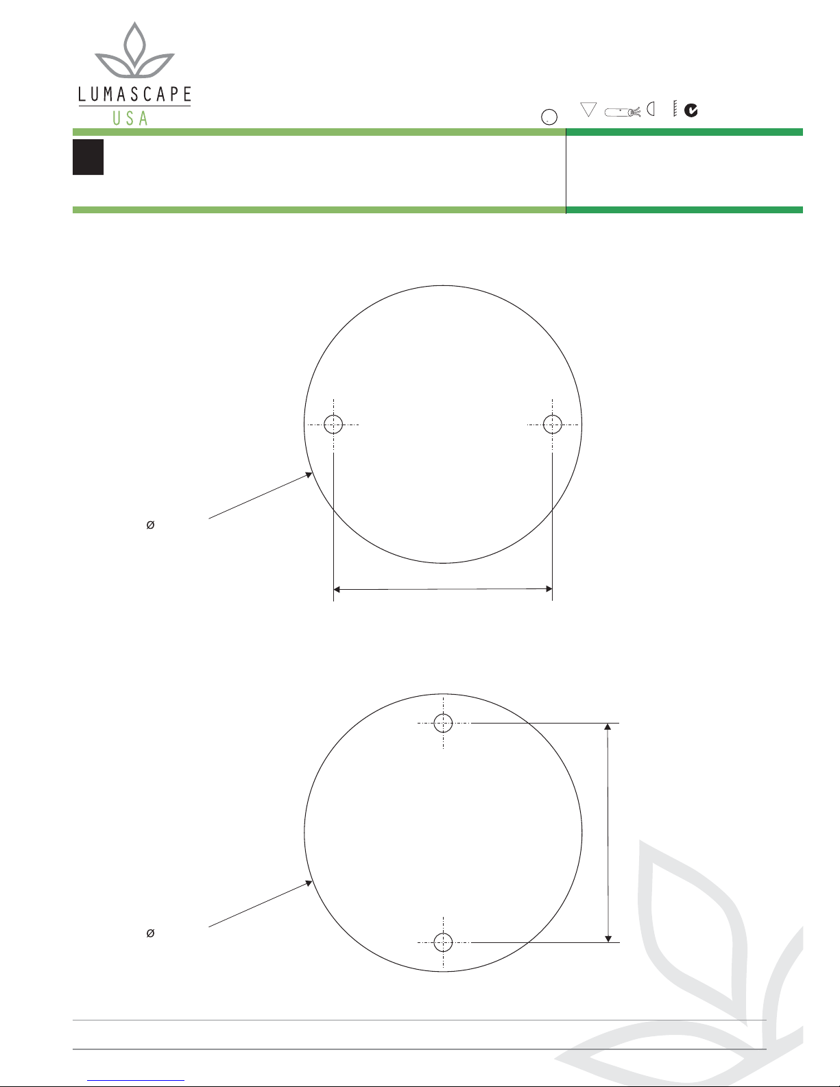
6. Fit the gasket to the stainless steel backing plate, ensuring
the indents on the seal match the positions of the screw lugs
on the backing plate (Figure B).
7. Before pressing the gasket down firmly, ensure alignment is
correct with the outside perimeter.
8. Fit the backing plate to the splice box cover with the cable
gland (Figure C).
9. Take supplied seal for the splice box cover and peel from
backing paper.
10. Fit seal to the back face of the splice box cover, ensuring
that the 3 holes match the 3 hole positions on the cover
(Figure D).
11. Make sure that the supply cable is plenum rated and fed
through a conduit attached to the splice box. Split cable and
strip ends to approximately 20mm (3/4”) (Figure E).
12. Feed the light fixture wires through the gland in the splice
box cover. Do not trim or strip end of light fixtures wires.
The full length of these wires is required for easy fixture
removal (Figure E).
13. Note that the supply cable is indexed (i.e. one side is
marked the other is not). Gather together indexed leg/s and
one of the fixture wires. Very lightly twist the strands
together. Then fit the yellow scotch lock connector applying
pressure as you twist it on. Keep twisting until very tight.
Repeat for remaining wires (Figure F).
14. Fasten the splice box cover to the splice box with the
supplied screws (Figure F).
15. Fasten the fixture’s rear canopy to the backing plate with the
supplied screws. It is advised to place silicone caulking
around the canopy when mounting (Figure F).
16. Connect supply cable to transformer making sure indexed
legs are grouped with indexed and non-indexed with non-
indexed legs.
17. Plug transformer into power point, switch on and check
each fixture is operating.
18. At night adjust and aim your fixtures to achieve the desired
effect (if applicable).
Overcurrent protection for the secondary circuit must be
provided at the supply transformer in accordance with the
National Electrical Code.
WARNING-
INSTALLATION DIAGRAMS OVERLEAF
www.lumascape.com
INC.
Lumascape USA Inc. 2006©
LUMASCAPE
HEAD OFFICE
T 07 3286 2299 F 07 3286 6599
LUMASCAPE
SYDNEY - NSW
T 02 9519 6860 F 02 9519 8834
LUMASCAPE
MELBOURNE - VIC
T 03 9686 1900 F 03 9686 1700
ECC LIGHTING
LUMASCAPE AGENT - NZ
T 09 379 9680 F 09 308 9328
H.I. LIGHTING
LUMASCAPE AGENT - WA
T 08 9321 5422 F 08 9321 5881
NQ LIGHTING
LUMASCAPE AGENT - NTH QLD
T 07 4031 4490 F 07 4031 5933
T 1-(650)-595-LUMA(5862) 1-(650)-595-5820
LUMASCAPE USA INC
Free Call 1-866-695-LUMA(5862)
LIGHTING PARTNERS AUSTRALIA
LUMASCAPE AGENT - SA
T 08 8232 0074 F 08 8232 0076
Lumascape USA Inc.
1300 Industrial Rd., Unit #19
San Carlos, CA 94070, USA
T 1-(650)-595-LUMA(5862)
F 1-(650)-595-5820
W www.lumascape.com
Free Call US & Canada1-866-695-LUMA(5862)
MODELS LS101A LS321A
LS321-2A LS121A-2
LS201-3
(Max. Wattage)
(50W), (50W),
(2x 50W), (35W IRC),
(2x35W IRC)