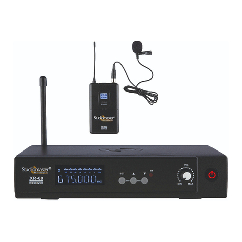
Studiomaster Professional XR-40 User manual

UHF Wireless Microphone System
XR-40
1. .......................................................................................................................Features
2........................................................................................................................Systems Components
3........................................................................................................................Operating Instructions
4........................................................................................................................Basic Troubleshooting
5........................................................................................................................Technical Specifications
6........................................................................................................................Safety Instructions
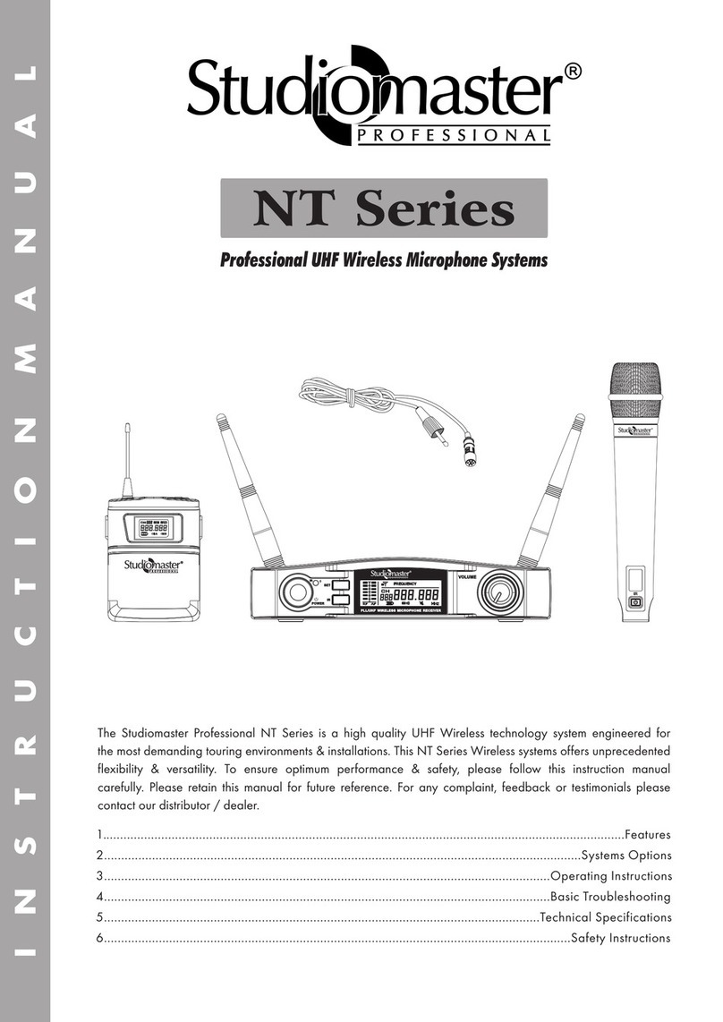
The Studiomaster Professional XR 40 is a high quality dual UHF Wireless technology system engineered for
the most demanding touring environments & installations. This XR 40 Wireless systems offers unprecedented
flexibility and versatility. To ensure optimum performance & safety, please follow this instruction manual
carefully. Please retain this manual for future reference. For any complaint, feedback or testimonials please
contact our distributor / dealer.
XR-40L
BO DY PAC K
POWER
WIRELESS MICROPHONE SYSTEM
CH CH
XR-40
RE CEI VER
VOL BVOL A
MIN MINMAX MAX
AF 1RF 1
AF 2RF 2
XR -40 H
On\Off
XR-40

1. Features
2
• High quality UHF band frequency duet Wireless
Microphone System.
• Individual channel output with level control & mix output.
2. System Options
• . • XR 40HL (Receiver + Handheld + Lapel)XR 40HH (Receiver + Handheld + Handheld)
• Lapel Lapel . • XR 40CC (Receiver + Conference + Conference). XR 40LL (Receiver + + )
3. Operating Instructions
3.1 Receiver Features: Front & Rear Panel
Rear Panel
4
3
1 12 2
BALANCED-B
ANT-B
MIX OUT
DC INPUT
12-15VDC
BALANCED-A
ANT-A
Front Panel
1. Antenna : The antenna receives signals from Transmitter, for better strength keep the antenna fully extended.
2. Balanced audio output : 3 Pin XLR female connectors are provided to connect to the input of the Mixer/Amplifier/
Powered speaker.
3. Mixed output : 1/4” (6.35) Unbalanced TRS Jack is provided to connect mixed output to the input of Mixer/
Amplifier/Powered speaker.
4. Power Jack : 12VDC Input voltage to power up the unit.
1. LED Screen : It displays frequency (fixed).
2. Audio Indication LED : This LED lights up when there will be signal reception.
3. Channel Select Indication : LED is provided to indicate the Transmitter is ON.
4. Volume Controls : To adjust the Input signal level.
5. Power ON/OFF Switch : To switch ON/OFF the receiver module.
3.2 Handheld Transmitter Features
XR -40H
On\Off
1 3 4
2
C H
796.8
M
H
Z
FREQUENCY
B
1. Grill : It protects the capsule from damages. Also it acts as an effective wind & pop filter.
2. Power Status & Battery Indication.
3. LED Screen : LED screen displays the channel frequency.
4. Power ON/OFF : Use This switch to power the transmitter ON or OFF.
POWER
WIRELESS MICROPHONE SYSTEM
CH CH
XR-40L
RE CE IV ER
VOL BVOL A
MIN MINMAX MAX
AF 1RF 1
AF 2RF 2
1 32 4 5
• UHF Operating Frequency Range: 740-790MHz.
• Display for frequency indication.
• Two microphones can be used at the same time.
Battery Indication:
i) Good /New Batteries: When the switch is pressed, the Red LED blinks once and goes OFF immediately.
The screen remains ON and displays the channel's frequency.
ii) Weak Batteries: When the switch is pressed, the Red LED remains ON continuously.
The screen remains ON and displays the channel's frequency.
iii) Dead Batteries: The ON/OFF switch does not function, the Red LED remains OFF and the screen displays the
channel's frequency.

3
3.5 Polar Pattern & Frequency Response Curve
1. Confirm the connections between receiver & mixer as well as between mixer & amplifier are correct. Turn down the volume
on the amplifier or mixer.
2. Turn on the receiver (The receiver will shows CH 1, CH 2 Frequency and RF 1, RF 2 LED will be off because transmitter is off).
3. Turn on the transmitter (Note: When transmitter is turned on the RF 1 & RF 2 LED lights up to indicate availability of Transmitter
1 & 2 respectively.
4. Test the transmitters. AF 1 & AF 2 LED lights up to indicate signal reception.
5. Turn up the volume in the amplifier or mixer.
3.6 How to operate
Usage Tips
- Make sure you can always see the receiver antenna from the transmitter position.
- Keep the distance from transmitter to receiver as short as possible
- Avoid obstruction between transmitter & receiver.
- Perform a ‘’Walk Test’’ before performance or presentation. If dead spots are found, adjust location of receiver. If dead
spots remain mark spots and avoid that spot.
Polar Pattern Frequency Response Curve
3.3 Body Pack Features
1. Antenna: Transmission Antenna.
2. Power ON LED: LED light when lapel body is switched on.
3. Mic Input: Input socket to connect lapel microphone.
4. Display : It display fixed frequency.
5. Power ON/OFF Switch : This switch can be used to
ON/OFF microphone as required.
6. Battery Cover: Slide downward for access to
the battery compartment.
7. Belt Clip: To hang on belt.
8. Microphone Head (Lapel).
7
4
6
1
5
2
3
782.30
MHZ
FREQUENCY
Lapel Microphone
8
3.4 Conference Transmitter Features
1
4
3
5
2
XR-40
6
1. Mic Capsule: This high quality microphone is used to pick up the
voice of the person speaking.
2. Mic LED: This LED displays the status of the microphone, when
the LED lights up it means that the microphone is active.
3. LED Display: It displays fixed frequency.
4. Low Power Indication: When microphone On/Off
switch is pressed the LED lights up & goes off.
Also when battery goes low the LED becomes brighter.
5. Microphone ON/OFF Switch: This switch is
used to switch ON/OFF the conference transmitter.
6. Battery Compartment: The system operates
with 2 x 1.5V AA Batteries.

* Design and specification are subject to change without notice.
is a registered trademark of Audioplus in India. © Copyright Audioplus, 2008. All rights reserved. Any
unauthorised reproduction or use of logos, images or design elements is strictly prohibited by law. No part of the
compilation may be reproduced in any manner or translated without written permission.
Rev002/SM XR 40/AUG 2020
A1/A2, Giriraj Industrial Estate, Mahakali Caves Road, Andheri (East), Mumbai - 400 093. India
Tel.: +91-22-428690000 / 01 Whats App.: +91-8879028079 E info@audioplus-india.com
W www.studiomasterprofessional.com / www.audioplus-india.com
No Voice; (Signal is normal) • Check whether the level control of the receiver is set enough.
• Check whether the connection between receiver & mixer, mixer & amplifier or
amplifier & speaker are connected. Also check mixer or amplifier volumes are ok.
No Voice; (RF signal is normal
but AF signal is weak)
• Check whether the transmitter battery is fully charged..
• Interchange the transmitter Mics.
When transmitter is ON, there
is noise or interruption in the
receiving signal.
• Check whether the battery is charged fully.
• Eliminate the RF source of the disturbance nearby which causes interference.
• If the signal is too weak, place the receiver closer to transmitter as far as possible.
RECEIVER
Operating Frequency response
Receiving Frequency
Bandwidth
Frequency Response
Nominal deviation / peak error
Total harmonic distortion
Sensitivity
Adjacent channel selection
Intermediation impedance
Noise filter
Power Requirement
740-790MHz
Fixed Frequency
50MHz
50Hz-16KHz
± 24KHz / ± 28KHz
<0.9%
-98dBm
> 75dB
> 70dB
> 75dB
DC 12V
TRANSMITTER
Carrier frequency
Frequency stability
Frequency response
Frequency bandwidth
Harmonic radiation
Maximum offset
Sensitivity
740~790 MHz
+0.005%
50Hz-16KHz
50MHz
< -55dB
± 60MHz
-80 ± 3dB
Use Battery 2 x 1.5V (AA)
5. Technical Specifications
6. Safety Instructions
• Keep the wireless receiver in a good location to ensure good signal strength.
• Please keep the product away from direct sunrays & rain.
• Please keep the product away from heavy magnetic or electromagnetic fields, it could affect product performance.
• Please switch off when removing the batteries.
• Please remove the batteries/ power supply when the product is not being used for a long time.
• Do not open any of the components yourself, for repairs please contact an authorised Studiomaster Professional dealer.
• Do not use systems with the same frequency at the same place, please separate them by a considerable distance.
4. Basic Troubleshooting
Solution
Problem
No Voice;
(No signal on receiver)
• Check whether power switches of transmitter & receiver are ON.
• Check whether the battery connections are correct & battery polarity is right in
transmitter. • Check whether the antenna is properly connected on receiver.
• Make sure that there is no obstruction between the antenna & the transmitter.
Table of contents
Other Studiomaster Professional Microphone System manuals
Popular Microphone System manuals by other brands
T.BONE
T.BONE Lucan System CC 200 RC quick start guide
himbol
himbol ZOlink Series quick start guide
Sony
Sony DWZM50 product manual
Better Music Builder
Better Music Builder VM-92U operating instructions
AlienPro
AlienPro MU-250 operating manual
Nady Systems
Nady Systems DigiTRU Diversity UB-33B owner's manual
