Studiomaster DQX Series User manual

DQX SERIES
Owner's Manual
Professional Amplifier
This manual does not contain all the information about the design, production,
and changes of the equipment, and does not cover all the conditions that may
occur during the installation, use and maintenance.
The information provided in this manual is accurate at the time of delivery of
the equipment, it maybe has been changed because of the product upgrade.
RS48 5
PUSH FO R DS P
DQX2-2000
RS485/ AE S
RS48 5
PUSH FO R DS P
DQX2-3000
RS485/ AE S
RS48 5
PUSH FO R DS P
DQX4-2600
RS485/ AE S
RS48 5
PUSH FO R DS P
DQX4-4000
RS485/ AE S

01
IMPORTANT SAFETY INSTRUCTIONS

02
PROFESSIONAL POWER AMPLIFIER
1 Welcome
1.1 Features
a、 90~260VAC / 50~60HZ Wide range power supply.
b、 high-definition audio DSP .
c、 Analog and AE S3 signals can be received.
d、RS485 serial communication port,for amplifier control and monitoring.
e、Modular design and maintenance is simple.
f、 2, 4 channel design,Very suitable for touring.
1.3 How to use this manual
This manual provides the basic information for the proper installation and use of the
equipment, and does not cover all the conditions that may arise in the actual project. For more
information, please visit our website or contact our technical support, system installation
personnel or agents.
Please take care of the sales order or invoice for your purchase of this equipment. You need
to show the credentials when the product is guaranteed.
2 Environmental protection, energy saving, cost saving
Thank you for your trust, buy our class D power amplifier!
Our company focuses on class D power amplifier. The high level of R&D team, experienced
production team and high-quality technical support team ensure that our products used in a variety
of environment are stable and reliable, and bring you a pleasant experience.
In order to maximize the efficiency of the equipment and bring you a pleasant experience, please
read this manual carefully.
1.2 Function
a、Audio input:AES3 digital audio and analog audio selectable.
b、Built-in 4X4 audio matrix.
c、Pushbutton for fast mute.
d、Mode: stereo, mono, bridge, one in four out.
e、15 segment parameter EQ.
f、Filter for each channel: direct,low pass,band pass,high pass,all pass.
g、Delay for each channel:0~65000us delay(step 1us).
h、Peak voltage limiter,Over temperature,Short protection.
、 .i Over load limiter
、 .j Under voltage, DC protection
k、Status to monitor:temperature,voltage,current,fault.
l、RS-485 address and Baud Rate settings;
m、16 memory spaces for parameter save and recall.

03
465mm
483mm
(370mm)
45mm
RS 485
PU SH FO R DSP
DQX2 -2000
RS 485/ AES
SUN ON
PMD1204 P QBX -A
(2).B2220.G N
DC12V —8.0W
SUN ON
PMD1204 P QBX -A
(2).B2220.G N
DC12V —8.0W
SUN ON
PMD1204 P QBX -A
(2).B2220.G N
DC12V —8.0W
SUN ON
PMD1204 P QBX -A
(2).B2220.G N
DC12V —8.0W
* Saving energy, reducing operating costs
* Environmental protection
Aluminum, copper and steel are greatly reduced, saving energy and resources;
reduce transportation emissions 70%.
Climate warming is a challenge to the world, energy saving and emission reduction
are effective measures to solve the climate.
We are committed to providing environmental friendly products. For blue sky ,
white clouds, green mountains and rivers ,let us act together!
3 Installation
3.1 Check out of the box
Open packaging and check whether the equipment is damaged in the transportation .
If the equipment is damaged, please inform the shipping company immediately, only you
have the right to request compensation for shipping damage. Please save the packing case
as evidence of damage for the shipping inspection. We will provide the necessary assistance
for you.
It is recommended that you save all packaging materials for use in the transportation
equipment. Do not transport the equipment in the absence of an outer package, so as not
to damage the equipment.
Packing list:
amplifier 1 pcs User's manual 1 pcs
Power cord 1 pcs
Machine foot 4 pcs
3.2 Outline dimensions

04
PROFESSIONAL POWER AMPLIFIER
3.3 Installation preparation
Warning: before installation, please confirm that you see and read
the safety warning.
The equipment is high power, around a strong magnetic field. Keep
the signal sensitive equipment away (preferably not less than 20cm),
ortherwise may produce noise.
For the normal operation, following parts is needed:
1、Input connection cable
2、Output connection cable
3、Ethernet cable (for Ethernet interface power amplifier)
4、Cabinets or equipment mounting rack
Before installation,make sure that the power cord is not connected to the
power outlet;The power switch is turned off;The volume knob is
completely.
3.4 Cooling instructions
The cooling mode of the equipment is as follow:
the cold air is sucked through the ventilation hole of
the front panel, and the heat are taken out from the
rear panel. In order to ensure good heat dissipation,
please put the equipment in the 0℃~40℃ environm
ent, and ensure that the front and rear panel airway
open. If the temperature exceeds 85 degrees, outp
ut voltage will be reduced, avoid excessive tempera
ture rise. If the temperature continues rise up to 90
degrees, the power amplifier will be shunted down,
when the temperature dropped to a safe temperat
ure, the equipment will restart automatically.
After working for some time, if the cooling effe
ct is not good, please turn off the equipment and re
move the dust net cover to clean up the dust.
3.5 Power cord
The grounding end of the power cord must be grounded,
otherwise there is a risk of electric shock!
PUSH FOR DSP
DG42 00
RS485/AE S3
PUSH FOR DSP
DG4200
RS485/A ES3
PUSH FOR DS P
DG4200
RS485/AE S3
PUSH FO R DSP
DG42 00
RS485/A ES3
PUSH FOR D SP
DG4200
RS485/A ES3
PUSH FOR D SP
DG42 00
RS485/AE S3
PUSH FOR DSP
DG4200
RS485/AE S3
PUSH FOR DSP
DG42 00
RS485/AE S3
PUSH FOR DSP
DG42 00
RS485/A ES3
PUSH FOR DS P
DG4200
RS485/AE S3
The power cord must have sufficient current capacity, AC power supply voltage and frequency
must be in range of ±10% of the nominal value.
3.6 Input / output line

05
Common knowledge:
Try to use the shielded wire, the higher density shielding layer is the better.
Try to select balance connection for input, to reduce noise interference.
Selection of non balance connection, the shorter the better, preferably not more than 3m.
The weak signal line should avoid to parallel with the power line and the power output line,
otherwise it might produce noise.
Before changing any connection, please turn off all equipments. Otherwise, it may cause
damage to hearing and speakers.
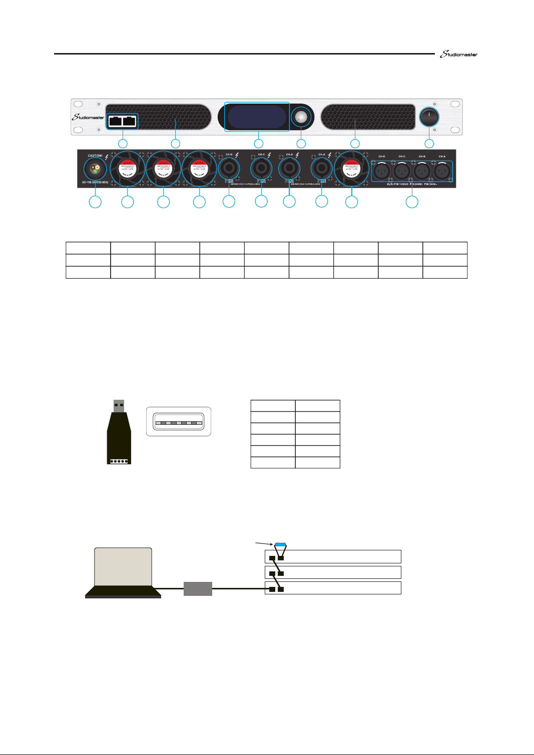
Balanced analog input Non balanced analog input
connection
GND SHIELD
4 Operating instructions
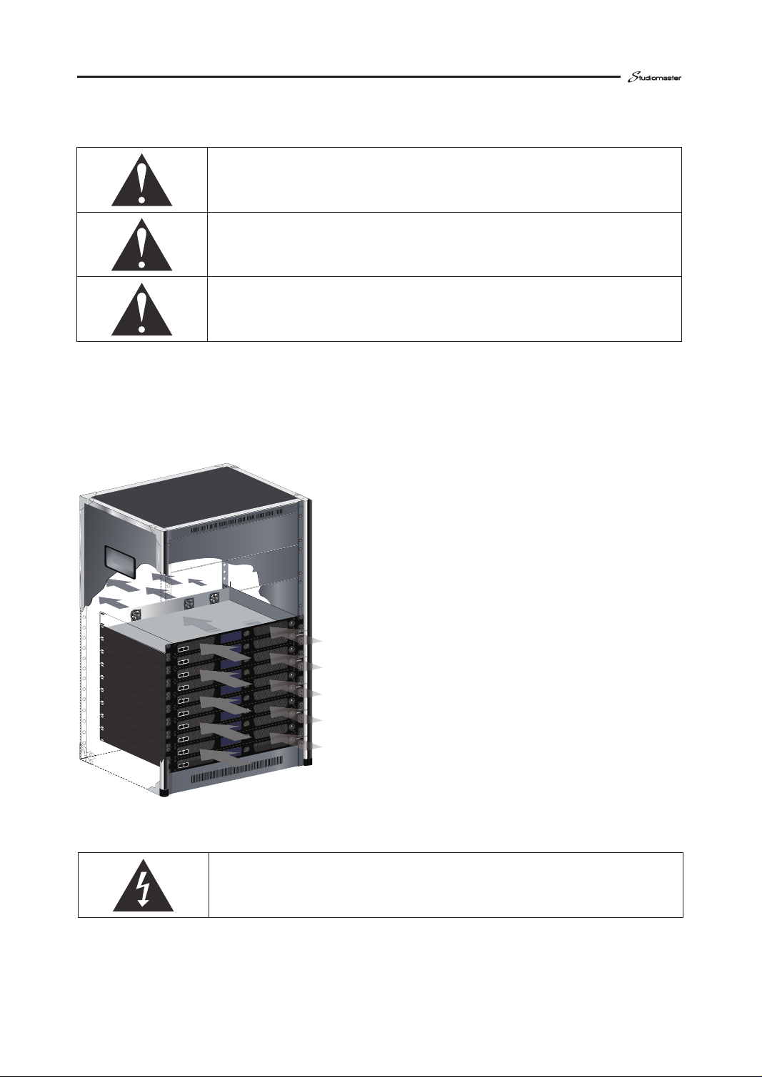
Before installation, make sure that the power cord is not connected to
the power outlet; the power switch is turned off; the volume knob is
completely closed (counter clockwise to the limit).
4.1 Protection speaker
Clipping not only makes sound distortion, but also damages the tweeter, you can reduce the
input signal to avoid clipping.
Strong sub signal will cause the speaker burned. The high level low frequency signal caused
by the falling of the microphone is a typical sub acoustic signal. One of the following ways to
prevent sub sonic signals should be used:
a、Installing a high pass filter between the mixer and amplifier.
b、Turn on the high pass filter in the mixer. Without affecting the use, the filter frequency is
set as high as possible. For example, for the music signal is set to 35Hz, for the microphone set to
75Hz.
4.2 Attention
In order to achieve the best performance and the highest security, please pay attention:
1、Before use, you need to configure the amplifier, including the input and output lines.
Improper wiring will lead to the equipment can not work properly. For information about connection
and configuration, please refer to the “installation” section of this manual.
2、Be careful when connecting, selecting the input signal and controlling the output level.
This can avoid unnecessary trouble.
3、 Do not connect the ground wire of the input and output cable together . This will form a
ground loop and cause oscillations.
4、Do not connect the output cable to the power supply, Otherwise it may cause electric shock.
5、Without authorization, modify the circuit will be dangerous, and the agents will not provide
any services.
6、Do not use the amplifier in the SIG LED continuous flashing yellow.
7、Do not make mixer overload, otherwise it will send clipping signals to the amplifier. Power
amplifier will accurately reproduce such signals, the speaker may be damaged.
8、Do not use the amplifier under the condition of lower than the nominal load. Too low load
may cause amplifier output protection and premature clipping ,damage the speaker.
9、When the amplifier is turned on, the output port may be fatal.
Important note: our company is not responsible for the damage caused by
excessive use.

06
PROFESSIONAL POWER AMPLIFIER
RS 485
PU SH F OR D SP
DQX2-2000
RS485/A ES
15
4
3
2 2
SU NON
PMD 1204PQ BX-A
(2).B 2220.GN
DC1 2V —8.0 W
SU NON
PMD 1204PQ BX-A
(2).B 2220.GN
DC1 2V —8.0 W
SU NON
PMD 1204PQ BX-A
(2).B 2220.GN
DC1 2V —8.0 W
SU NON
PMD 1204PQ BX-A
(2).B 2220.GN
DC1 2V —8.0 W
69
88
7 7
88
7 7
4.3 Operation
1、RS485 serial communication port,AES3 digital audio input port.
2xRJ45 port,the port is defined as follows:
PIN1 PIN2 PIN3 PIN4 PIN5 PIN6 PIN7 PIN8
RJ45 PIN#
RS485_A RS485_B AES1/2+ AES3/4+ AES3/4- AES1/2- Reserved
Signal
White/Green Green White/Orange Blue White/Blue Orange
White/Brown
Brown
Wire Color
Reserved
◇Instructions for connecting amplifier and computer(RS485):
Hardware preparation:
a、Recommended configuration of computer: Windows XP and above, Windows 10
recommended.Display resolution greater than 1366 x 768;
b、USB-RS485 adapter: it is recommended to adopt the USB to serial port scheme of CH340,
485half duplex communication; and correctly install the USB to serial port driver; (the
following figure shows the common adapter, only connect two wires a and B to the RJ45
port of power amplifier)
c、Adapter to RJ45 port of power amplifier: Category 5 line and above.
◇Online steps:
a、Connect the hardware as shown in the figure below:
Connection precautions:
I、In order to ensure the normal communication, the RJ45 port at the end of the bus needs
to be equipped with a 120ohm impedance matcher;
II、The line sequence of USB-RS485 adapter and RJ45 port of power amplifier shall be the
same, RJ45 Pin1 = 485 A, RJ45 Pin2 = 485 B;
b、The 485 address and baud rate of the machine can be set through the front panel rotary
1
Item Pin definition
1
2
3
4
5
A
B
GND
GND
+5V
PC
Amplifier 1
Amplifier 2
Amplifier 3
USB-RS485 adapter
120ohm,Resistance

07
2、Cooling Vents:Front-to-rear forced airflow through foam dust filter.
3、LCD Display Screen.
4、Control Button:turn for previous and next ,push for enter.
5、Power Switch:ON/OFF . It is ON to press “I” down .
6、Power cord:Configuration 3×1.0mm², 3×1.5mm² or 3×2.5mm² cord according to power .
7、Fans:Provide front-to-back forced airflow for cooling.
8、Output sockets.
To wire stereo or mono speakers to the Output sockets, use below method:
To wire Bridge speakers to the Output sockets, use below method:
2+ 1-
2-
1+
+
-
CH-A/B/C/D
8Ω
4Ω
2Ω
b、 encoder, as shown in the following figure;
Setting considerations:
I、485 address setting range: 1-255, 485 address of equipment under the same bus cannot be
repeated;
II、The baud rate range is 1920-115200, and the baud rate of the equipment under the same
bus shall be set to be consistent; the baud rate shall be set according to the transmission
distance and rate. The lower the baud rate is, the farther the transmission distance is. The
higher the baud rate is, the closer the transmission distance is. It is recommended to set
3840;
c、Open the upper computer software of the computer, click "search", the amplifier under the
bus will be displayed in the list, double-click or right-click to enter the power amplifier
configuration interface;

08
PROFESSIONAL POWER AMPLIFIER
MENU:
1. Volume
2. Mode
4. Gain
5. Mute
MAIN CHA
CHB
CHC
CHD
EXIT
Volume gain:
CH_AB
CH_CD
EXIT
Mute control :
CHA
CHB
CHC
CHD
EXIT
3. Source
Input Source:
Analog
AES
EXIT
MODE:
STRO
MONO
BRDG
1IN-4OUT
EXIT
5.2 MENU TREE
5.1 DSP signal processing flow
5 Advanced Operation
Analog audio
AES digital audio
A/D
convertor
AES
decoder
Input Source
Configuration Audio routing Volume gain 15 segment
parameter EQ
Filters:
direct,
low pass,
band pass,
high pass,
all pass.
Delay
Limiter
Mute control Mode control
Volume channel selection:
......
To wire Bridge speakers to the Output sockets, use below method:
9、Balanced Analog XLR Inputs:3-pin female XL R connector for each channel.
2+
1-
2-
1+
+
-
8Ω
4Ω
CH-A/C

09
......
6. Delay
7. Filter
8. DSP bypass
9. EQ
Delay:
CHA
CHB
CHC
CHD
EXIT Filters:
Highpass
Freq
Type
Lowpass
Freq
Type
EXIT
Filters:
CHA
CHB
CHC
CHD
EXIT
DSP Bypass:
CHA_Bypass
CHB_Bypass
CHC_Bypass
CHD_Bypass
EXIT
EQ parameter adjust:
CH select
Band select
Type select
Freq adjust
Boost
Q
EXIT
12. Standby
13. Address
14. Save/Recall
Standby setup:
Normal
Standby
EXIT
Save
Recall
Clear
EXIT
485 parameter settings:
Address
Baudrate
EXIT
Restore factory settings
11. Status
TEMP
Pro.
Load
EXIT
15. Reset
Status view:
10. Limiter
RMS Limiter
Channel
Attack (ms)
Release (ms)
Threshold (dB)
Switch
EXIT
Save and recall settings:
......

10
PROFESSIONAL POWER AMPLIFIER
Click on the corresponding process box to make corresponding parameters and process
settings.
Click on the following flow chart:
Input A\Input B\Input C\Input D
Output Gain1\Output Gain 2
OUT A\OUT B\OUT C\OUT D
The parameters are set as follows:
Volume independent adjustment of channels A, B, C and D(-80dB~0dB)
MUTE independent adjustment of channels A, B, C and D(ON\M U TE)
6.1 software flow pattern
6.2 Volume adjustment and MUTE
6 Software settings
16. Contrast
18. Exit
17. Cursor
Contrast adjustment of display screen:
Contrast
B/L Mode
EXIT
Cursor settings:
Clockwise up
Clockwise down
EXIT
......

11
Can be set: STRO (Stereo), MONO , BRGD (Bridge) ,ONE IN (1 in 4 out )
four modes.
The flow chart of each channel is as follows
STRO(Stereo)
MONO
6.4 MODE
Gain 1 control the gain of channel A and B, the gain range is shown in Tab 9.
Gain 2 control the gain of channel C and D, the gain range is shown in Tab 9.
6.3 Gain adjustment

12
PROFESSIONAL POWER AMPLIFIER
Options: Analog (analog audio input), AES (AES3 digital audio input), AUTO (digital
audio priority, automatic switching between analog and AES3)
6.5 INPUT(Signal source selection)
6.6 DSP Bypass
BRGD(bridge)
ONE IN(1 in 4 out)

13
Low pass filter types (12\24\48dB-Bworth, 12\24\28dB-Bessel, 12\24\48dB-Lnkwtz)
24dB-Bworth
12dB-Bworth
Crossover-Click the image to change the high and low frequency
(20Hz-20KHz).
6.7.1 LowPass(low pass filter):
6.7 Crossover

14
PROFESSIONAL POWER AMPLIFIER
48dB-Bworth
12dB-Bessel
24dB-Bessel
DSP Bypass switch

15
12dB-Lnkwtz
24dB-Lnkwtz
48dB-Lnkwtz
Frequency-Input low pass filter frequency (20Hz~20kHz)
48dB-Bessel

16
PROFESSIONAL POWER AMPLIFIER
24dB-Bworth
12dB-Bworth
48dB-Bworth
12dB-Bessel
High pass filter types (12\24\48dB-Bworth, 12\24\28dB-Bessel, 12\24\48dB-Lnkwtz)
6.7.2 High Pass(High pass filter):

24dB-Bessel
48dB-Bessel
12dB-Lnkwtz
24dB-Lnkwtz
17

48dB-Lnkwtz
Frequency-Input high pass filter frequency (20Hz~20kHz)
Switch channel
Parametric EQ- the type, frequency, gain and Q value of each segment are settable.
PEQ-1:
6.8 Parametric EQ
18
PROFESSIONAL POWER AMPLIFIER

Switch Band
Switch Filters Type(ByPass、Peaking、Low Shelf、High Shelf)
Bypass
Peaking
19
Table of contents
Other Studiomaster Amplifier manuals

Studiomaster
Studiomaster ARC 120A User manual

Studiomaster
Studiomaster DJA 100 User manual

Studiomaster
Studiomaster DX400 User manual

Studiomaster
Studiomaster DJA 550 User manual

Studiomaster
Studiomaster SX225 User manual

Studiomaster
Studiomaster ARENA 15 User manual

Studiomaster
Studiomaster DPA 5000 User manual

Studiomaster
Studiomaster QX Series User manual

Studiomaster
Studiomaster HX Series User manual

Studiomaster
Studiomaster DJA 5000 User manual