Studiomaster SLA 40 User manual

Index:
1.............................................................................................................Introduction
2.............................................................................................................Features at a Glance
3.............................................................................................................onfiguring & Setting-Up
4......................................................................................................... ...Rigging Instructions
5.............................................................................................................Flying Patterns
6.............................................................................................................Connection Diagrams
7.............................................................................................................Technical Specifications
SLA 40
Line Array System
I N S T R U C T I O N M A N U A L
1

2
1. Introduction
Thank you for purchasing the Studiomaster Professional SLA 40 Line Array System.
To ensure optimum performance and safety, please follow this instruction manual carefully.
Please retain this manual for future reference.
For any complaint, feedback or testimonials please contact our distributor / dealer.
The SLA 40 is a specially designed loudspeaker module designed to form a vertical stack in varying numbers.
This stack is usually flown to provide superior sound coverage in the intended listening areas. Stacked SLA 40
modules form a line array for constructive summing and increased coupling. Sound dispersion of SLA 40 array
has a very narrow vertical dispersion angle. Therefore sound can be precisely directed where audience is
present.
The SLA 40 has a maximum hinge of 10°, variable in steps of 2°. This hinge is enough to provide necessary tilt
in a typical J or spiral array. The SLA 40 is capable of producing peak SPL of 132dB with its dual LF drivers and
twin HF drivers. For achieving even sound pressure levels in the audience areas, SLA 40 is provided with a
switch for altering its sensitivity from nominal 0dB to -3, - 6 and -9dB. The SLA 40 has a full frequency response
ranging from 80Hz to 20kHz. However for delivery of bass frequencys, it is complemented with Subwoofer
model SLA 40S, SLA 40S is designed for ground level stacking.
SLA 40T: The SLA40T incorporates 2 x 8”
Mid-Bass transducers & 1” High Duty HF transducer
with state of the art Waveguide horn, all comprised
into a sleek & lightweight enclosure. This Array
module has a horizontal coverage angle of 100°
& vertical Coverage angle of 10°.
SLA 40 System Consists of:
SLA40T
Dual 8", 2-Way 400 Watts @ 8 Ω, Passive Line Array Module.
About Waveguides:
Sound Waves in open space propagate in all directions, this way they lose their
power significantly. In order to counter this problem the SLA-40T incorporates
waveguide driver to ensure maximum control on power & dispersion. This ensures
pure performance and negates the possibilities of phase cancellations.
SLA 40S
Dual 15", 800 Watts @ 4 Ω, Passive Line Array Sub Woofer.
SLA 40S: The SLA-40S incorporates 2 x 15”
Powerful Low Frequency Transducers for extended
sub filling. The enclosure is specially designed to
deliver high SPL and long excursion, without being
very bulky.

Important Concept of Line Array:
In the case of normal loudspeakers, as sound travels, its SPL (Sound Pressure Level) falls by 6dB for every
doubling of distance. In the case of a Line Array the fall in SPL is 3dB for every doubling of distance up to a
certain distance called transition point. Beyond that the fall in SPL is 6dB for every doubling of distance as in
the case of normal loudspeakers.
The transition point is dependent on the length of the line array. Longer the array, further away is the transition
point. Therefore if near equal SPL is desired spanning the front row to the last row, it is recommended to have
more numbers of SLA 40T enclosures stacked vertically in spiral formation.
3
SLA 40KIT
Fly Bars & Quick Release Pins.
SLA40 Kit: The SLA40 Kit is set of essential
hardware required for rigging & flying this line
array system. It consist of ultra durable Flybars /
Array Frames & Quick Release Pins
(Push-Pull Bullets). This kit makes flying the
SLA40 Series a child’s play.
2. Features at a Glance
• Higher direct to reverberant ratio due to the directional nature of the system.
• Increased feedback rejection due to directionality in vertical plane & therefore more acoustic gain available.
• Frequency response is uniform over the coverage area.
• Because of increased HF throw of the system, need for delay stacks is eliminated or reduced.
• Even sound pressure level can be achieved over the entire listening area by proper articulation of the vertical
array formed by SLA 40.
• More stage space available as SLA 40 arrays are flown.
3. Configuring & Setting-Up
SLA 40T enclosures can be flown or ground stacked. For small venues or temporary/rental installations where flying
SLA 40T may not be possible, these can be ground stacked on top of its sub-woofer SLA 40S.
When ground stacked, the SLA 40T enclosures are generally kept straight i.e., all enclosures have 0° tilt without any
splay. Two to four SLA 40T enclosures may be adequate for small venues. A pair (in Left & Right placement) of this
set-up i.e., two to four SLA 40T with one SLA 40S will provide very even coverage and used for stereo reproduction of
program as well.
As a thumb rule for every four nos. of SLA 40T one SLA 40S subwoofer should be employed. When multiple
sub-woofers are used it is better to stack these together for coherent lows. The location of the sub-woofers should be
beneath the stage and centrally positioned.

When SLA 40T enclosures are flown, it is possible to configure these in any one of the following
formation:
Straight Array – In this type all enclosures have 0° tilt. ll modules
are arrayed vertically without any downward tilt. This formation
gives a narrow long throw beam. Such an array will not find
deployment in a practical setup because of its very narrow coverage
in vertical plane.
A
SLA 40T disperses sound as a line source with a vertical beam angle of 10° & horizontal beam angle of 100°. A very
simplistic depiction of this is shown below.
HORIZONTAL BEAM
100°
VERTICAL BEAM
10°
4
Curved Array – In this type, the enclosures are configured as an
arc of a circle. The upper enclosures radiate sound upwards toward
the ceiling & the lower enclosures have a wide lower fill. Such an
array has the widest possible coverage in the vertical plane & is not
suitable for long throw requirement. This configuration is suitable for
small venues and if installed indoors, the venue should have acoustic
treatment with highly absorbent ceiling.

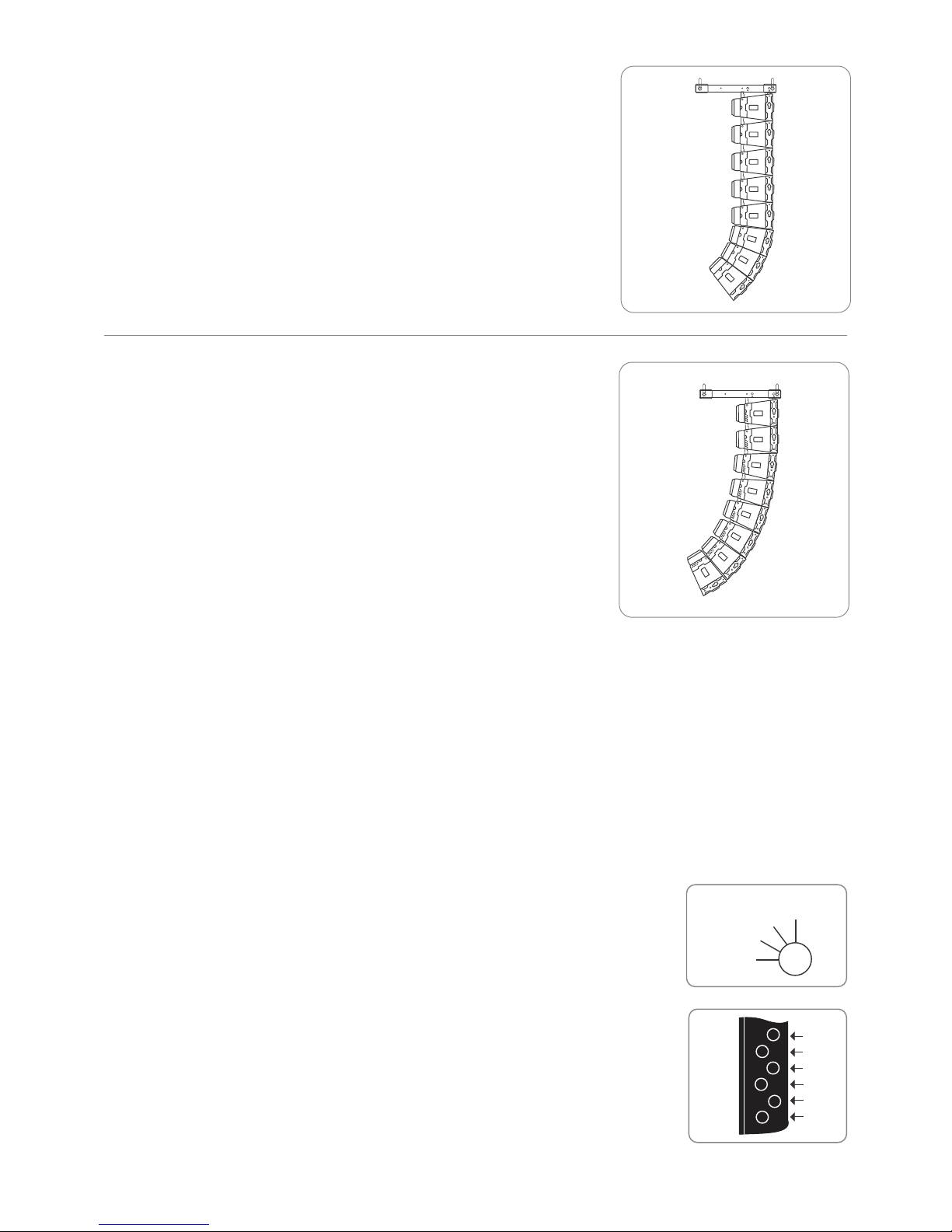
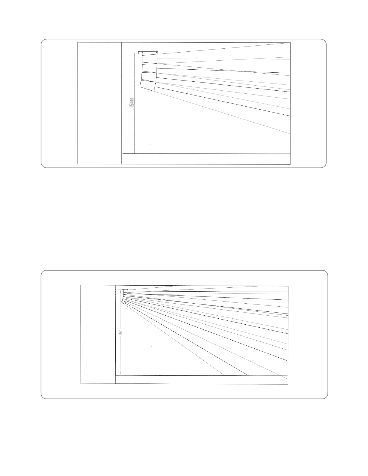
Spiral or Progressive Array - Unlike a J-Array, spiral or progressive
array is a continuous curve. The upper portion of the array is nearly
straight but then increases in curvature towards the bottom. Most small
and mid-sized venues get covered very well with this type of array
formation and we recommend this formation when installing four to
eight SLA 40T. This would be the situation with majority of the installers
of SLA 40T. With this configuration one can expect very uniform
coverage over the entire audience area. In a spiral array the angle
between successive enclosures changes by a predetermined incremental
angle. SLA-40T has provision for 0°-2°-4°-6°-8°-10° tilt angles.
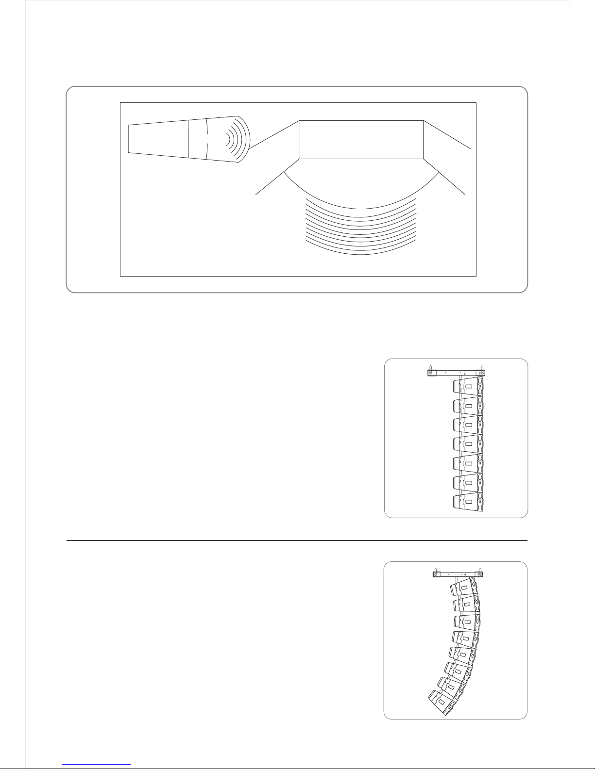
J-Array – This is a combination of straight and curved arrays. In the
real world Line Arrays are almost always used as curved vertical arrays.
A large venue may consist of a dozen enclosures, with top two to four
enclosures straight with 0° vertical splay, aimed at the farthest seats.
As we move down the array, the angle between adjacent enclosures
increases until at the bottom there are one or two modules aimed
almost straight down to cover the front seating area. Therefore a
J-Array has upper portion of the array as straight and then increases
in curvature toward the bottom giving the array the shape of letter J.
Therefore the incremental angle of 2° will yield 0°, 2°, 6°, 12°, 20°, 30°,40°, 50° aiming angles relative to the
horizontal when eight SLA 40T enclosures are flown. The topmost module has 0° tilt and lowest (eighth) has 50° tilt
relative to horizontal.
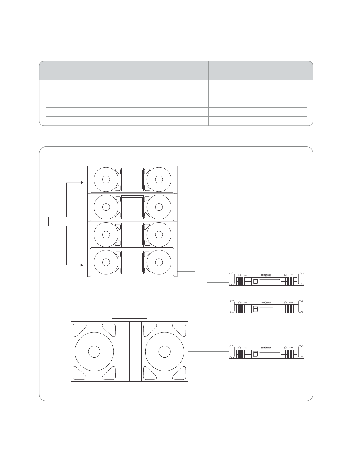
Powering of topmost enclosure is at full power and subsequent ones are progressively turned down a little. This way
a reasonably even coverage with almost equal SPL in the front seating area and farthest seating area is achievable.
SLA40T has a switch for providing HF attenuation of -3dB,-6dB, & -9dB. This feature can be utilized during
equalization of the frequency response. A reasonably even frequency response in the entire listening area is also
aided by the wave-guide loaded HF drivers of SLA 40T.
-9dB
-6dB
-3dB
-0dB
Sensitivity Settings: The sensitivity knob is located on rear panel of the
SLA 40T. This is used to adjust the HF attenuation of the SLA 40T module.
A flat screwdriver can be used to change settings as required.
Splay / Tilt Angle: This set of angled grooves can be used to tilt the
modules in perspective to the other stacked modules, in order to form the
numerous flying configurations.
10°
8°
6°
4°
2°
0°
5
Table of contents
Other Studiomaster Recording Equipment manuals