Studiomaster CLUBXS10 User manual

CLUBXS8/10
CLUBXS

1
Service Information
If you have a problem with your Studiomaster product or think it has developed a
fault contact your local dealer or distributor for service details.
Should it be recommended you return the product to your nearest Studiomaster
Service Centre you must first contact them.
You will be asked for the product type and serial number. You will then be given a
Returns Authorisation (RA) number.
Pack the unit in its original carton to protect it from shipping damage.
You must have the Returns Authorisation number clearly marked on the outside of
the carton or we may refuse the delivery. Studiomaster cannot be held responsible
for damage resulting from the equipment being packed incorrectly.
Label the equipment clearly with your name and address and include a clear
description of the fault. The more information you supply helps the service engineer,
minimising repair cost when out of warranty.
Please write your Serial number here for future reference....

2
1. Introduction
Thank you for Studiomaster CLUBXS8/10 compact mixer which features universal voltage
100-240V, compression function of each mic channel to keep crystal clear sound during
performance. The mixer can play the music via SD card/USB/bluetooth. The mic sound or
music of line in can be recorded to SD card/USB to suit for the requirement of solo or band
performance or conference recording.
Application
suitable for the applications in PA system or indoor recording, e.g.Movie/TV/music
recording in theatre/dancing hall/bar/conference hall, etc;
2. Function
1) 4-6 CH MIC/line and 2CH stereo inputs;
2) Compression function of mic channels (0-9dB);
3) Built-in USB/SD card/bluetooth playing/recording function;
4) 48V phantom power for condenser mic;
5) Built-in 16 program DSP with adjustable delay for wonderful effect;
6) Main outputs with 2X8 accurate meter to monitor output level;
7) Universal voltage 100V-240V;
Specification
Mono input
Mic input
Bal input
Frequency response 10 Hz to 30 kHz, +/-3 dB
THD(THD&N) 0.03% at +4 dBu, 22Hz-20kHz A-weighted
Compression
S/N ratio (SNR)115 dB
Line in Bal input
Frequency response 10 Hz to 30kHz, +/-3 dB
THD(THD&N)
Max gain
Stereo input channel
Line in
Frequency response
0.005% at+4 dBu, 22Hz-20kHz A-weightde
75 dBu MIC INPUT MAIN OUTPUT
Bal/unbal
10 Hz to 55 kHz, +/-3 dB
THD(THD&N) 0.005% at +4 dBu, 22Hz-20kHz A-weighted
Impedance
1.4 kOhm
Mic input
Line in 10 kOhm
Other inputs 10 kOhm or more
Recording output 1 kOhm
Other outputs
Mono EQ
HI
MID
LOW
Low cut filter
120 Ohm
+/-15 dB @12 kHz
+/-15 dB @2.5kHz
+/-15 dB @45Hz
80 Hz, 18dB/Oct.
A/D &D/A converter sample frequency 24-Bit 16 programsDSP
AUX +22 dBu
100-240 VAC~50/60 Hz
Main mix
Power supply
DSP +22dBu
Noise (BUS noise)
Fader 0dB,all input channel knobs set to minimum,
EQ knobs set to middle,:-100dBu(reference:+4dBu)
Max output Bal +27dBu unbal +22dBu 1/4 connector
Dimension(D*W*H)mm
Net weight
CLUBXS8: 358X280X76
GAIN:0-9dB,THRESHOLD: 20dB 5dB
HI +/-15 dB @12 kHz
LOW +/-15 dB @60Hz
CLUBXS10: 358X336X76
CLUBXS8: 4kg CLUBXS10: 4.5kg
11

3
A. Channel
1. MIC/LINE CHANNEL(CH1-6)
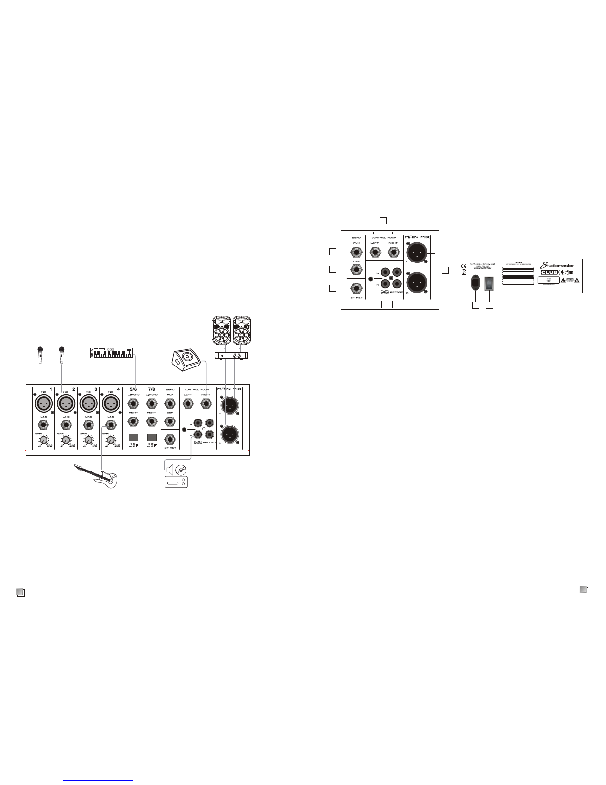
Balanced XLR input connector (1 ground 2 hot 3 cold).
CLUBXS8 Is designed with 4 low noise mic pre-amp (CLUBXS10
has 6) and phantom power, 45dB gain and >100 dB S/N ratio. The
phantom power is used for condenser mic. If you use dynamic mic,
please turn off phantom power first. These channels are designed
with 1/4inch TRS bal/unbal line ine connectors to connect with
keyboard, electric drum, DSP, etc.
3. COMP
2. Gain control
It adjusts input signal level to balance the S/N ratio and dynamic
range. To get best effect, adjust this knob: make PEAK LED flashes
sometimes to avoid channel distortion.
Mic input gain range: -16~-60dB, line in gainrange: +10~ -34.
5. EQ control
1
2
7
8
10
3
5
6
9
4
4. HPF
It turns on/off the HPF with 18 dB octave to activate 80 Hz LF filter.
You can also use it to reduce mains hum noise or stage mic noise.
Hi when you set it to max, 12 KHZ frequency level boosts +15dB.
To min, and the 12 kHz frequency levelcuts -15dB
MID when you set it to max, 2.5 KHZ frequency level boosts +15dB.
To min, and the 2.5 kHz frequency level cuts -15dB.
LOW when you set it to max, 4.5HZ frequency level boosts +15dB.
To min, and the 4.5 kHz frequency level cuts -15dB
6. AUX-DSP
7. PAN
Set it to middle position, then sound image will be in the middle of
the stage. It can also adjust the left/right output signal.
8. PEAK LED
When signal reaches the level of clipping level deducted 3dB,
PEAK LED lights up red.
9. MUTE &LED
Each channel is designed with MUTE button. Press it to mute
the channel. The mute LED lights up.
It adjusts channel compression. Turn clockwise to increase
compression ratio and gain willadjust automatically.
BLOCK DIAGRAM
10
These two knobs are used to the level of signal sent to AUX-DSP
BUS, and then to external DSP, or to built-in DSP module. DSP knob
can also adjust channel level.

9
Bal/unbal mode of TRS/XLR connectors
1/4 TRS or XLR connector bal/unbal modes; please refer to below:
1/4 connector
XLR connector
Connection
The supplied 1/4 TRS and XLR connector to connect with pro audio equipments;
please refer to below:
TS unbal TRS bal TRS unbal
XLR unbal XLR bal
Balanced
Unbalanced
4
Stereo channel
10. FADER
It adjusts the level of channel signal which is sent to main mix out.
Note: set the unused faders to minimum position.
1
2
3
4
5
6
7
8
9
1. Stereo channel input
Unbalanced connectors. If signal input from LEFT/MONO, the signal
outputs from L/R main mix outputs. If signal inputs from RIGHT
connector, signal outputs from R main mix output. This connector
can be connected with keyboard, electric drum, DSP, etc.
2. -10/+4 sensitivity switch
Press t his switch, this sensitivity will be 10dB higher.
3. LINE/USB/MP3 selection switch
Release for stereo line input. Press for USB/MP3/bluetooth input.
4. EQ control
Hi: set to maximum position, and 12 KHz frequency level boosts +15dB.
Set to minimum position, and 12 kHz frequency level cuts -15dB.
LOW: set to maximum position, and 60 KHz frequency level boosts +15dB.
Set to minimum position, and 60 kHz frequency level cuts -15dB.
5. AUX-DSP
These two knobs are used to the level of signal sent to AUX-DSP
BUS, and then to external DSP, or to built-in DSP module. DSP knob
can also adjust channel level.
6. PAN
Set it to middle position, then sound image will be in the middle
of the stage. It can also adjust the left/right output signal.
7. PEAK LED
When signal reaches the level of clipping level deducted 3dB,
PEAK LED lights up red.
8. MUTE BUTTON & MUTE LED
Each channel is designed with MUTE button. Press it to mute the
channel.The mute LED lights up.
9. FADER
It adjusts the channel level.
Note: set the faders of unused channels to minimum position to
reduce noise.

8
Installation
1. There should be no obstacles before the speaker cabinet. You had better put the speaker
cabinet on a speaker stand.
2. Use professional devices to suspend or install the speaker cabinets to avoid hurt.
3. Use high quality cable to ensure the best tone.
4. Please match the right power and impedance of power amplifier and speaker cabinet.
5. Do not point the microphone to the speaker cabinet to avoid feedback.
Power amplifier
Passive speaker cabinet
Monitor speaker cabinet
Microphone
Keyboard
CD player
Guitar
5
1. AUX SENDS
1/4" phone jacks to send signal from AUX BUS to external equipments, e.g. Effect
equipment or stage monitor, etc;
2. DSP output
1/4" phone jack to output DSP signal and the level is controlled by channel DSP.
3. AUX RETURNS input
Stereo 1/4" phone jacks to return effect equipment stereo signal to Main Mix. Or you can
Use AUX RETURN knob to adjust volume. The input AUX signal will be sent to MAIN MIX.
Unbal RCA and 3.5 connectors to input signal from CD player/computer, etc;
5. RECORD
Unbal RCA connector to output signal to recording equipment.
6. MAIN MIX output
Bal XLR connector. The level is adjusted by Main Mix fader.
7. CTRL ROOM output
1/4" phone jacks send Control Room signal to monitor speaker cabinet.
8. POWER socket
It is designed with fuse to connect with mains. Please replace the fuse with the
same type and rating.
9. POWER swtich
It turns on/off the mixer.
4. PLAYBACK
89
OUTPUT AND REAR PANEL
1
2
3
45
6
7

7
SD/USB/BLUETOOTH
1. MODE
Press this button to select mode: SD card, USB, bluetooth, recording.
a) SD/USB mode: insert SD card/USB to play music directly.
b) Bluetooth mode press the button to select bluetooth, then match the bluetooth,
then play music.
c) Recording mode press the button to select recording mode. Input signal from
mic or line, then
press play button to record.
The LCD displays recording symbol flashing.
2. Play/pause button
3. Stop button
4. Repeat button
5. Previous button
6. Next button
7. Sd card input connector
8. USB input connector
123456
7
8
1. +48V phantom power switch/red when on
It is used for condenser mic operation. Please
set all faders to minimum before turning on the
switch to protect speaker cabinets.
2. Stereo return
It adjusts stereo return signal level.
3. AUX send
It adjusts aux send level.
4. PLAYBACK
It adjusts the playback signal level.
5. CTRLMP PHONES
It adjusts the phone signal level.
6. PLAYBACK switch
Press the switch to send signal to monitor
and phones.
7. MAIN MIX switch
Press the switch to send MAIN signal to
monitor and phones.
8. Phone output
This connector send signal to phones.
9. DSP ON switch
Press this switch to start DSP operation and
LED lights up green.
10. DSP fader
It adjusts the DSP signal level.
11. PARAMETER
It adjusts thedelay time.
12. PROGRAM
13. POWER LED
14. PEAK LED
15. MAIN OUTPUT LEVEL LED
16. MAIN MIX fader
It adjusts theMAIN MIX outpu t level.
1
2
3
4
5
6
7
8
9
10
11
12
13
14
15
16
Prg#
Small Hall
Large Hall
Small Room
Bright Room
Thin Plate
Large Plate
Spring Reverb
Multi-tap Delay
Analog Delay
Chorus Verb
STEREO CHORUS
Flanger
Gated Reverb
Phaser
Flange Verb
Vocal Echo
Description Parameter 1
Rev Time
Rev Time
Rev Time
Rev Time
Rev Time
Rev Time
Rev Time
Rev Time
Rate
Rate
Rate
Gate Time
Rev Time
Delay Time
Delay Time
Delay Time
0.9sec~3.5sec
1.5sec~8.6sec
0.28sec~0.82sec
0.36sec~1.38sec
0.44sec~1.54sec
0.72sec~10sec
0.4sec~2.3sec
0.56sec~3.5sec
0.58Hz~11Hz
0.58Hz~6Hz
0.58Hz~4.35Hz
0~680ms
0~680ms
0.25sec~0.78sec
0.34sec~2sec
0~400ms
48v
1
2
3
4
5
6
7
8
9
10
11
12
13
14
15
16
6
123456
7
8
This manual suits for next models
1
Table of contents
Other Studiomaster Recording Equipment manuals