StumpJumper EVO ALLOY User manual

EVO ALLOY
USER MANUAL


CONTENTS
1. INTRODUCTION................................................................ 1
1.1. INTENDED USE ....................................................................................................................................................................1
1.2. WARRANTY .........................................................................................................................................................................1
2. GENERAL NOTES ABOUT ASSEMBLY .....................................2
2.1. FORK/HEADSET.................................................................................................................................................................2
2.2. SEATPOST .........................................................................................................................................................................2
2.3. BOTTOM BRACKET ..........................................................................................................................................................3
2.4. REAR AXLE........................................................................................................................................................................3
2.5. DERAILLEUR HANGER.....................................................................................................................................................3
2.6. STEM ..................................................................................................................................................................................3
3. GENERAL NOTES ABOUT MAINTENANCE ............................... 4
4. SPECIFICATIONS ............................................................ 5
4.1. GEOMETRY.........................................................................................................................................................................5
4.2. GENERAL SPECIFICATIONS............................................................................................................................................6
4.3. SHOCK CUSTOMIZATION ................................................................................................................................................ 7
4.4. TOOLS REQUIRED ............................................................................................................................................................ 7
4.5. BOLT SIZE / TOOLS / TO TORQUE SPECIFICATIONS................................................................................................... 7
4.6. GENERAL TORQUE SPECIFICATIONS ........................................................................................................................... 8
4.7. BEARING SPECIFICATIONS .............................................................................................................................................8
4.8. SPACER/AXLE/BOLT SPECIFICATIONS .........................................................................................................................8
5. REAR TRIANGLE PIVOT ASSEMBLY...................................... 11
5.1. BEARING ASSEMBLY ........................................................................................................................................................11
5.2. PIVOT ASSEMBLY............................................................................................................................................................13
5.3. SUSPENSION TORQUE SPECIFICATIONS ....................................................................................................................17
6. INTERNAL ROUTING ....................................................... 17
6.1. DROPPER SEATPOST ......................................................................................................................................................17
6.2. REAR DERAILLEUR AND REAR BRAKE........................................................................................................................19
6.3. REAR BRAKE CABLE BAT..............................................................................................................................................22
7. FLIP CHIPS & HEADSET Cups ........................................... 22
7.1. ADJUSTING THE HORST PIVOT FLIP CHIP...................................................................................................................23
7.2. ADJUSTING THE HEAD TUBE ANGLE..........................................................................................................................23
8. AIR SHOCK SETUP ......................................................... 27
8.1. SETTING AIR PRESSURE................................................................................................................................................27
9. DERAILLEUR HANGER ..................................................... 28
10. SMALL PARTS.............................................................. 29
We may occasionally issue updates and addendums to this document. Please periodically check
www.specialized.com or contact Rider Care to make sure you have the latest information.
Info: specialized.com / 877-808-8154
SPECIALIZED BICYCLE COMPONENTS
15130 Concord Circle, Morgan Hill, CA 95037 (408) 779-6229
0000164477_UM_R1, 03/21

1
1. INTRODUCTION
This user manual is specific to your Specialized Stumpjumper Evo Alloy bicycle. It contains
important safety, performance and technical information, which you should read before your
first ride and keep for reference. You should also read the entire Specialized Bicycle Owner’s
Manual (“Owner’s Manual”), because it has additional important general information and
instructions which you should follow. If you do not have a copy of the Owner’s Manual, you
can download it at no cost at www.specialized.com, or obtain it from your nearest Authorized
Specialized Retailer or Specialized Rider Care.
Additional safety, performance and service information for specific components such as
suspension or pedals on your bicycle, or for accessories such as helmets or lights, may
also be available. Make sure that your Authorized Specialized Retailer has given you all
the manufacturers’ literature that was included with your bicycle or accessories. If there is
a difference between the instructions in this manual and the information provided by the
component manufacturer, please refer to your Authorized Specialized Retailer.
When reading this user manual, you will note various important symbols and warnings, which
are explained below:
WARNING! The combination of this symbol and word indicates a potentially
hazardous situation which, if not avoided, could result in serious injury or
death. Many of the Warnings say, “you may lose control and fall.” Because
any fall can result in serious injury or even death, we do not always repeat
the warning of possible injury or death.
CAUTION: The combination of the safety alert symbol and the word CAUTION
indicates a potentially hazardous situation, which, if not avoided, may result in
minor or moderate injury.
The word CAUTION used without the safety alert symbol indicates a situation
which, if not avoided, could result in serious damage to the bicycle or the
voiding of your warranty.
INFO: This symbol alerts the reader to information which is particularly
important.
GREASE: This symbol means that high quality grease should be applied as
illustrated.
CARBON FRICTION PASTE: This symbol means that carbon friction paste
should be applied as illustrated to increase friction.
TECH TIP: Tech Tips are useful tips and tricks regarding installation and
use.
1.1. INTENDED USE
The Specialized Stumpjumper Evo Alloy bicycles are intended and tested for Mountain Bike
(condition 4) use only.
For more information on the intended use and structural weight limits for the frame and
components, please refer to the Owner’s Manual.
1.2. WARRANTY
Please refer to the written warranty provisions provided with your bicycle, or visit
www.specialized.com. A copy is also available at your Authorized Specialized Retailer.

2
2. GENERAL NOTES ABOUT ASSEMBLY
This manual is not intended as a comprehensive assembly, use, service, repair, or
maintenance guide. Please see your Authorized Specialized Retailer for all service, repairs, or
maintenance. Your Authorized Specialized Retailer may also be able to refer you to classes,
clinics, or books on bicycle use, service, repair, and maintenance.
WARNING! Due to the high degree of complexity of the Stumpjumper Evo Alloy
Evo Alloy, proper assembly requires a high degree of mechanical expertise,
skill, training, and specialty tools. Therefore, it is essential that the assembly,
maintenance and troubleshooting be performed by an Authorized Specialized
Retailer.
WARNING! Many components on the Stumpjumper Evo Alloy, including, but not
limited to the rear suspension, are proprietary to the Stumpjumper Evo Alloy.
Only use originally supplied components and hardware at all times. Use of other
components or hardware will compromise the integrity and strength of the
assembly. Stumpjumper Evo Alloy specific components should only be used on
the Stumpjumper Evo Alloy and not on other bicycles, even if they fit. Failure to
follow this warning could result in serious injury or death.
In order to successfully build the Stumpjumper Evo Alloy bicycles, it is
very important to follow the order of operations as outlined in this manual.
Modifying the order of assembly will result in a longer build process.
2.1. FORK/HEADSET
The headset uses a 1 1/8” (41.8 mm x 30.5 x 8 mm, 45 x 45°) Campagnolo Standard
compatible upper bearing and a 1.5” (52 mm x 40 x 7 mm, 45 x 45°) lower bearing. Ensure
that replacement bearings are compatible with the Specialized headset specification.
No tools are needed for installation or removal of both bearings. Grease bearing surfaces
before installation.
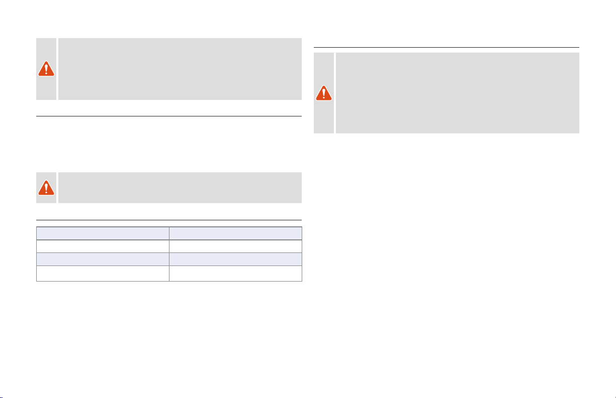
2.2. SEATPOST
SEATPOST MINIMUM INSERTION:
Both the frame and seatpost have minimum insertion requirements. In addition, the frame has
a maximum insertion requirement to prevent damage to the frame and seatpost.
MINIMUM INSERTION: The
seatpost must be inserted into the
frame deep enough so the minimum
insertion/maximum extension
(min/max) mark on the seatpost
is not visible. The frame requires a
minimum of 100 mm of insertion.
MAXIMUM INSERTION: The
seat tube is reamed to a specified
maximum insertion depth for each
frame size. This ream depth limits
the insertion depth of the seatpost.
Please refer to the table in Fig. 2.1.
If the desired seat height cannot be
achieved within the minimum and
maximum insertion requirements,
the seatpost should be replaced for a
shorter or longer one.
Once the saddle height is
determined, torque the seatpost collar bolt to manufacturer specifications.
The specified ream depths are listed in the table in Fig. 2.1. The tolerance of
the ream depth can vary from frame to frame. Install a regular 34.9 seatpost
in the seat tube to verify the actual ream depth of the frame.
The seat tube is designed for a 34.9 post but a 30.9 seatpost can be used
with a shim.
2.1
SIZE MAX INSERTION
S1 190
S2 190
S3 210
S4 230
S5 250
S6 270
MAX

3
WARNING! Failure to follow the seatpost and frame insertion requirements
(Fig. 2.1) may result in damage to the frame and/or seatpost, which could
cause you to lose control and fall.
If the seatpost is cut short, the min/max mark on the seatpost may no longer
be accurate. Before cutting the seatpost, note the min/max depth required by
the seatpost manufacturer.
WARNING! For general instructions regarding the installation of the seatpost,
refer to the appropriate section in the Owner’s Manual. Riding with an
improperly tightened seatpost can allow the saddle and seatpost to slide down,
which can damage the frame and cause you to lose control and fall.
2.3. BOTTOM BRACKET
Stumpjumper Evo Alloy models have a 73 mm BSA threaded bottom bracket shell. Please refer to
the crank manufacturer documentation for bottom bracket compatibility.
2.4. REAR AXLE
All Stumpjumper Evo Alloy models are equipped with 148mm Boost rear hub spacing and
require compatible 148mm Boost rear wheel.
2.5. DERAILLEUR HANGER
The Stumpjumper Evo Alloy frame uses the SRAM UDH (Universal Derailleur Hanger) at the rear
dropout. This hanger must be installed following SRAM’s installation instructions. Please refer to the
installation steps in section 9, or refer to the SRAM UDH User Manual.
2.6. STEM
Some Stumpjumper Evo Alloy models are equipped with an Alloy Trail Stem.
WARNING! The trail stem is designed with no gap between the stem body and
the faceplate at the upper bolt area. The upper bolts must be tightened such that
the faceplate bottoms out against the stem body before being torqued. Failure to
bottom out the faceplate against the stem body can result in structural damage to
the handlebar.
B
A
2.2
Fig. 2.2
Install the stem on the steerer tube.
Install the top cap and compression bolt (A) in the star nut in the fork, then tighten the bolt
to 27 in-lbf / 3 Nm or until all of the parts are snug and settled.
You should not be able to rotate the stem spacers by hand if the system is
sufficiently tightened.
With the bike on the ground, pull the front brake and rock the bike back and forth to ensure
the headset is fully seated and there is no looseness.
Align the stem with the front wheel and torque the rear stem bolts (B) to specification.

4
NO GAP
GAP
C
D
C
D
2.3
LOCATION DESCRIPTION TORQUE
in-lbf Nm
BStem Bolts 71 8
C / D Faceplate Bolts 53 6
Fig. 2.3
Loosely thread the stem bolts through the faceplate and into the stem body.
Position the handlebar to the desired position.
Gradually torque the upper bolts alternating from the left to right bolt to evenly increase the
torque until the spec is reached (C).
Gradually torque the lower bolts alternating from the left to right bolt to evenly increase the
torque until the spec is reached (D).
Check that the handlebar is installed correctly by rotating the handlebar up and down, then
twisting the handlebars side to side while holding the front wheel. If there is any movement,
the stem is not sufficiently tightened and should be re-torqued.
3. GENERAL NOTES ABOUT MAINTENANCE
The Stumpjumper Evo Alloy is a high performance bicycle. All regular maintenance,
troubleshooting, repair, and parts replacement should be performed by an Authorized
Specialized Retailer. For general information regarding maintenance of your bicycle, please
refer to the Owner’s Manual. In addition, routinely perform a mechanical safety check before
each ride as described in the Owner’s Manual.
Great care should be taken not to damage carbon fiber or composite material. Any damage
may result in a loss of structural integrity, which may result in a catastrophic failure. This
damage may or may not be visible in inspection. Before each ride and after any crash,
you should carefully inspect your bicycle for any fraying, gouging, scratches through the
paint, chipping, bending, or any other signs of damage. Do not ride if your bicycle shows
any of these signs. After any crash, and before you ride any further, take your bicycle to an
Authorized Specialized Retailer for a complete inspection.
While riding, listen for any creaks as a creak can be a sign of a problem with one or more
components. Periodically examine all surfaces in bright sunlight to check for any small
hairline cracks or fatigue at stress points such as welds, seams, holes, and points of
contact with other parts. If you hear any creaks, see signs of excessive wear, discover any
cracks (no matter how small), or find any damage to the bicycle, immediately stop riding
the bicycle and have it inspected by your Authorized Specialized Retailer.
Lifespan and the type and frequency of maintenance depends on many factors, such as
use, rider weight, riding conditions and/or impacts.
Exposure to harsh elements, especially salty air (such as riding near the ocean or in the
winter), can result in galvanic corrosion of components such as the crank spindle and
bolts, which can accelerate wear and shorten the lifespan. Dirt can also accelerate wear
of surfaces and bearings. The surfaces of the bicycle should be cleaned before each ride.
The bicycle should also be maintained regularly by an Authorized Specialized Retailer,
which means it should be cleaned, lubricated, and (partially) disassembled and inspected
for signs of corrosion and/or cracks . If you notice any signs of corrosion or cracking on the
frame or any component, the affected item must be replaced.
Regularly clean and lubricate the drivetrain according to the drivetrain manufacturer’s
instructions.
Do not use a high pressure water spray directly on the bearings. Even water from a garden
5
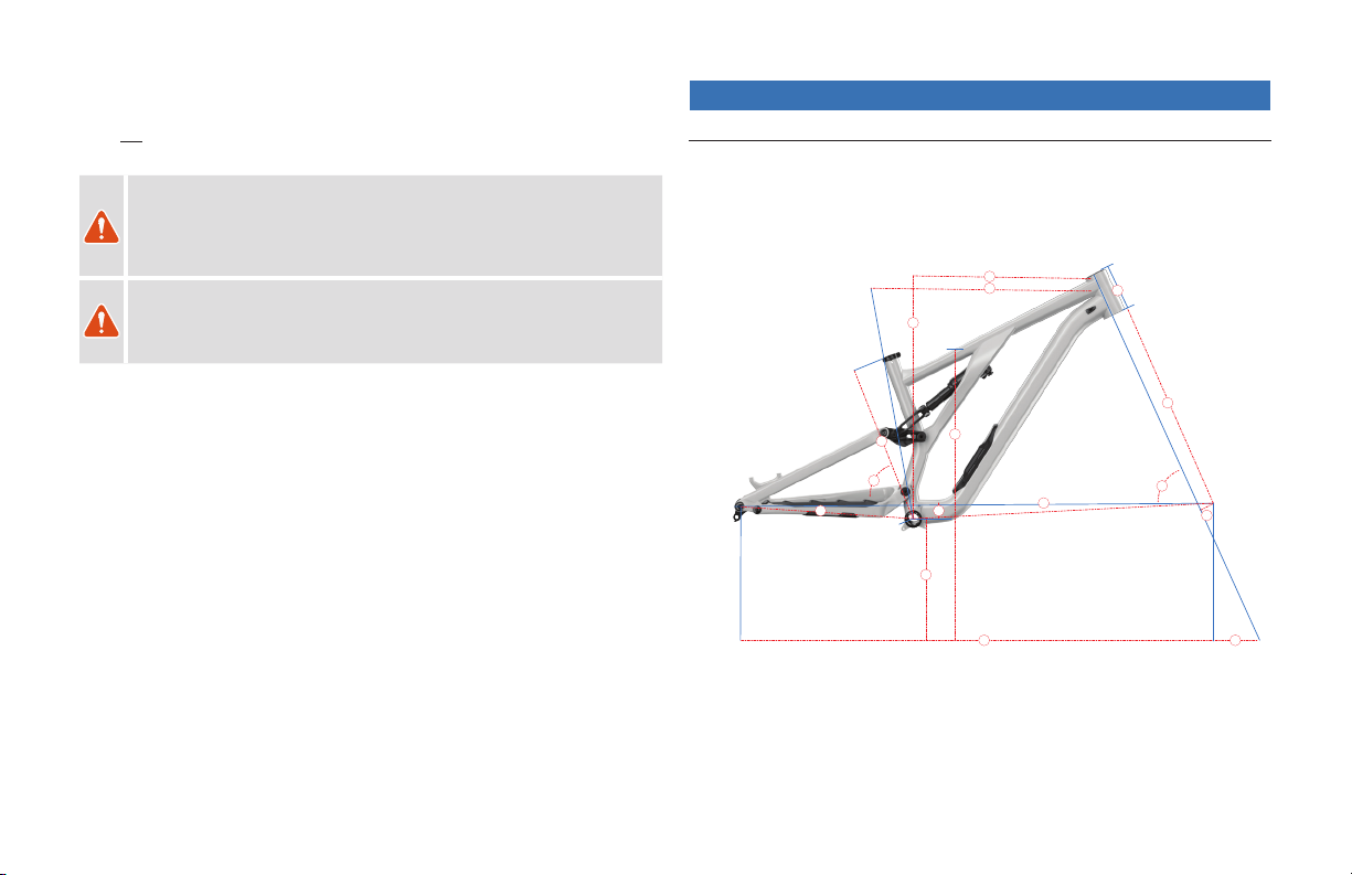
4. SPECIFICATIONS
4.1. GEOMETRY
A
B
C
D
O
E
F
G
H
I
J
K
L
M
N
P
hose can penetrate bearing seals and crank interfaces, increasing bearing and crank wear.
Use a clean, damp cloth and bicycle cleaning agents for cleaning.
Do not expose the bicycle to prolonged direct sunlight or excessive heat, such as inside a
car parked in the sun or near a heat source such as a radiator.
WARNING! Failure to follow the instructions in this section may result in
damage to the components on your bicycle and will void your warranty, but,
most importantly, may result in serious personal injury or death. If your bicycle
exhibits any signs of damage, do not use it and immediately bring it to your
Authorized Specialized Retailer for inspection.
WARNING! When placing the frame and/or bicycle in a repair stand, clamp
the stand to the seatpost and not the frame. Clamping the frame can cause
damage to the frame that may or may not be visible, and you may lose control
and fall.

6
FRAME SIZE S1 S2 S3 S4 S5 S6
A STACK (MM) 614 617 626 635 644 654
B REACH (MM) 410 428 448 475 498 528
C HEADTUBE LENGTH (MM) 95 95 105 115 125 135
D HEADTUBE ANGLE ( °) 64.5 °
EBB HEIGHT (MM) 335 340 340 340 340 340
F BB DROP (MM) 40 35 35 35 35 35
GTRAIL (MM) 131
H FORK LENGTH (FULL) (MM) 561 571 571 571 571 571
IFORK RAKE/OFFSET (MM)44
J FRONT CENTER (MM) 734 756 780 809 838 873
K CHAINSTAY LENGTH (MM) 441 441 441 441 451 451
L WHEELBASE (MM) 1172 1195 1219 1249 1288 1322
M BIKE STAND-OVER HEIGHT (MM) 746 749 757 760 784 792
N SEAT TUBE LENGTH (MM) 385 385 405 425 445 465
O SEAT TUBE ANGLE ( °) 78 ° 77.6 ° 77.2° 77 ° 77 ° 77 °
P TOP TUBE LENGTH (HORIZONTAL) (MM) 541 564 590 623 647 679
CRANK LENGTH (MM) 165 170 170 170 170 175
HANDLEBAR WIDTH (MM) 800
STEM LENGTH (MM) 40 40 50 50 50 50
SADDLE WIDTH (MM) 155 155 143 143 143 143
SEATPOST MAX INSERTION (MM) 190 190 210 230 250 270
SEATPOST MIN INSERTION (MM) 100
REAR WHEEL WIDTH (MM) 148
FORK SIZE (MM) 160
The above table shows the standard geometry for the bikes as shipped. Visit
www.specialized.com for all possible geometry configurations.
4.2. GENERAL SPECIFICATIONS
ITEM PART # SPECIFICATION
HEADSET S182500005 SPECIALIZED INTEGRATED 1 1/8 UPPER, 1 1/2 LOWER
SEAT COLLAR S184700004 SPECIALIZED SL SEAT COLLAR (KCNC-SPL-SC02-38.6)
SEAT COLLAR DIAMETER 38.6 MM
SEATPOST DIAMETER 34.9 MM
DERAILLEUR HANGER S202600002 SRAM UDH (00.7918.089.000)
BOTTOM BRACKET SHELL BSA THREADED 73 MM
CHAINGUIDE TABS ISCG-05
REAR HUB AXLE S170200003 148 X 12 MM THRU-AXLE; M12 X 1.0 THREADS
REAR TIRE MAX 29 X 2.5”
REAR WHEEL TRAVEL 150 MM
SHOCK LENGTH / STROKE S1:190 MM / 42.5 MM; S2-S6: 190 MM / 45 MM
SHOCK SAG 13.5 MM (30%)
SHOCK EYELET 8 MM ID X 20 MM W
MAX FORK TRAVEL 150 MM
MIN / MAX CHAINRING 28 - 34T
MIN / MAX REAR BRAKE ROTOR 180 / 203 MM
WARNING! While the Stumpjumper Evo Alloy frame is generally compatible
with tires up to 29 x 2.5, tire dimensions can vary depending on the
manufacturer.
WARNING! Not all forks are designed to accept a larger tire. Always check
with the fork manufacturer regarding required clearances.
CAUTION: Certain chainrings may not have adequate clearance with the
chainstay. Verify spacing and chainline before using it.
7
4.5. BOLT SIZE / TOOLS / TORQUE SPECIFICATIONS
WARNING! Correct tightening force on fasteners (nuts, bolts, screws) on your
bicycle is important for your safety. If too little force is applied, the fastener
may not hold securely. If too much force is applied, the fastener can strip
threads, stretch, deform, or break. Either way, incorrect tightening force can
result in component failure, which can cause you to lose control and fall.
Where indicated, ensure that each bolt is torqued to specification. After your
first ride, and consistently thereafter, recheck the tightness of each bolt to
ensure secure attachment of the components. The following is a summary of
torque specifications in this manual:
WARNING! Your bicycle is supplied with a suspension fork which was
selected, tuned, and approved for the frame. The use of different aftermarket
forks (less or more travel or a different style of fork), much like is the case
with any aftermarket parts, may negatively impact geometry and/or ride
quality, and, in some circumstances, may result in a catastrophic failure of
the frame or its components. Please check with your Authorized Specialized
Retailer or suspension manufacturer regarding aftermarket fork compatibility
4.3. SHOCK CUSTOMIZATION
Specialized frames are generally designed and tested to work with the suspension
components provided as original equipment. When changing out shocks, be aware certain
models of shocks may not be compatible with the frame due to the position of the shock
reservoir, size, and/or other compatibility factors, even if they fit. Always check with your
Authorized Specialized Retailer or suspension manufacturer for advice on compatible shocks.
WARNING! Use of an incompatible shock may cause damage to the shock
or the frame and can cause you to lose control and fall. Do not install
incompatible suspension parts.
4.4. TOOLS REQUIRED
2.5, 3, 4, 5, 6, 8 mm ALLEN (HEX) KEYS LIQUID BLUE LOCTITE 243
TORQUE WRENCH (reversible type, for SRAM UDH) GREEN LOCTITE 603
HIGH PRESSURE SHOCK PUMP CABLE AND HOUSING CUTTERS
HIGH QUALITY GREASE
8
4.6. GENERAL TORQUE SPECIFICATIONS
LOCATION TOOL TORQUE
(In-lbf) (Nm)
SEAT COLLAR 4 mm HEX 55 6.2
12 MM REAR AXLE 6 mm HEX 133 15.0
DERAILLEUR HANGER 8 mm HEX 221 25.0
WATER BOTTLE BOLT 3 mm HEX 25 2.8
ISCG TABS BASED ON CHAIN GUIDE
YOKE CABLE FUNNEL 3 mm HEX 7 0.8
MAIN PIVOT CABLE FUNNEL 2.5 mm HEX 13.2 1.5
HEAD-TUBE ICR GUIDE SCREW 2.5 mm HEX 13.2 1.5
SIDE ARM COVER 2 mm HEX 6.2 0.7
SEAT-STAY CABLE BAT SCREW 3 mm HEX 7 0.8
SWAT BEZEL 2.5 mm HEX 6 0.7
CAUTION (non-pivot bolts): Ensure all contact surfaces are clean and greased.
4.7. BEARING SPECIFICATIONS
QTY PIVOT LOCATION
DIMENSION
BEARING
A2MAIN PIVOT (CHAINSTAY) 15 ID X 24 OD X 7 W DOUBLE ROW 3802
B6LINK
12 ID X 21 OD X 5 W 6801
C4HORST
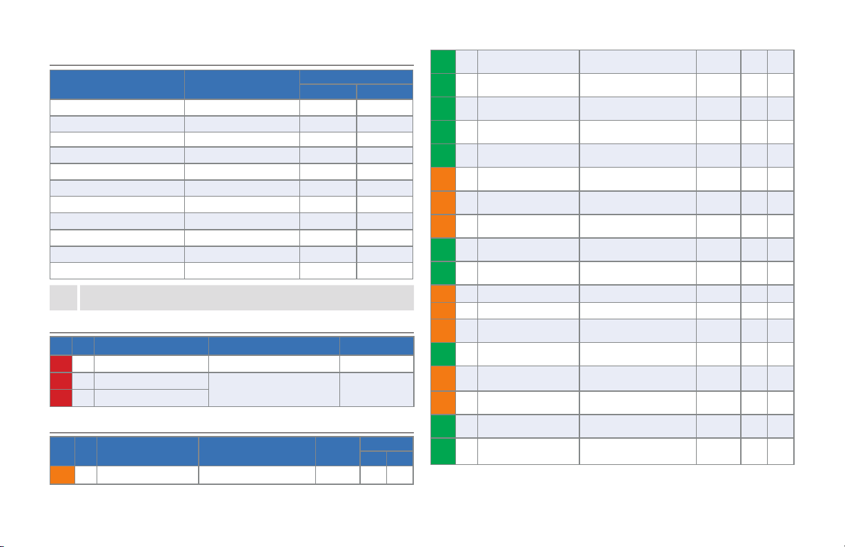
4.8. SPACER/AXLE/BOLT SPECIFICATIONS
QTY LOCATION / ITEM
DIMENSIONS
TOOL
TORQUE
IN-LBF NM
D2 HORST PIVOT BOLT SCR,CUST,M6 X 1.0 X 32.5,STL,BLK 5 MM HEX 90 10
E2HORST PIVOT ADJUSTABLE
SPACER OUTSIDE
DO PIVOT SPACER,GEO ADJ,6.0
ID, FLAT - - -
F2HORST PIVOT ADJUSTABLE
SPACER INSIDE DO PIVOT SPACER,GEO ADJ,M6 X 1 - - -
G4HORST PIVOT OUTER SPACER HORST PIVOT OUTER SPACER
ASSY 12 X 21 X 2.5 - - -
H2HORST PIVOT CENTER
SPACER
SPCR,STEP,6 MM ID X 16 MM OD X
16MM W,7075-T6 - - -
I2MAIN PIVOT SPACER SPCR,15.1 ID X 21.5 OD X 2.5
W,FSR,AL7075 - - -
J1MAIN PIVOT BOLT DS (LEFT
HAND THREAD)
SCR ASSY,CUST,OD 15 X ,M14 X
1,7075,LH,BLK 6 MM HEX 210 24
K1MAIN PIVOT BOLT NDS SCR ASSY,CUST,OD 15 X ,M14 X
1,7075,BLK 6 MM HEX 210 24
L2LINK @ SEAT STAY BOLT SCR,SHLDR, CUST, M12 X 1.0 Ø12 X
27,CHROMOLY 6 MM HEX 180 20
M4LINK @ SEAT STAY SPACER SPCR,12.1 ID X 19.5 OD X 3
W,FSR,AL7075-T6 - - -
N4LINK @ EXTENSION SPACER SPCR,CUST, 10 ID X 18.5 OD X 2.5
W,FSR,AL7075-T73 - - -
O2LINK @ EXTENSION BOLT SCR,CUST,M6X1.0 X 8,SST 302 4 MM HEX 60 7
P2LINK @ EXTENSION AXLE AXLE,SS PIVOT,MTB,TRAIL FSR L1 5 MM HEX 60 7
Q2LINK @ SEAT TUBE BOLT SCR ASSY,M12 X 1.0 X 17,21MM
HEAD,FSR 6 MM HEX 180 20
R2LINK @ SEAT TUBE SPACER SPCR,12.1 ID X 19.5 OD X 3
W,FSR,AL7075-T6 - - -
S1FORWARD SHOCK EYELET
BOLT SCR,CUST,M8X1.0 X 42,CHROMOLY 6 MM HEX 90 10
T1REAR SHOCK EYELET BOLT SCR,CUST,M8X1.25 X 27,CHOMOLY 6 MM LR
HEX 180 20
U1REAR SHOCK EYE WASHER WSHR,FLAT,M8,8.2 ID X 13 OD X
0.5 THK,304 SST - - -
V2REAR SHOCK EYE TOP HAT
SPACER
SPACER,SHOCK, 19 X 8.1 X 0.6,
SST 304 - - -

9
MN
RR
NB
M
N
B
B
A
I
A
I
N
M
B
M
B
G
C
C
G
H
G
C
H
C
G
B
4.1 EXPLODED VIEW - BEARINGS/SPACERS
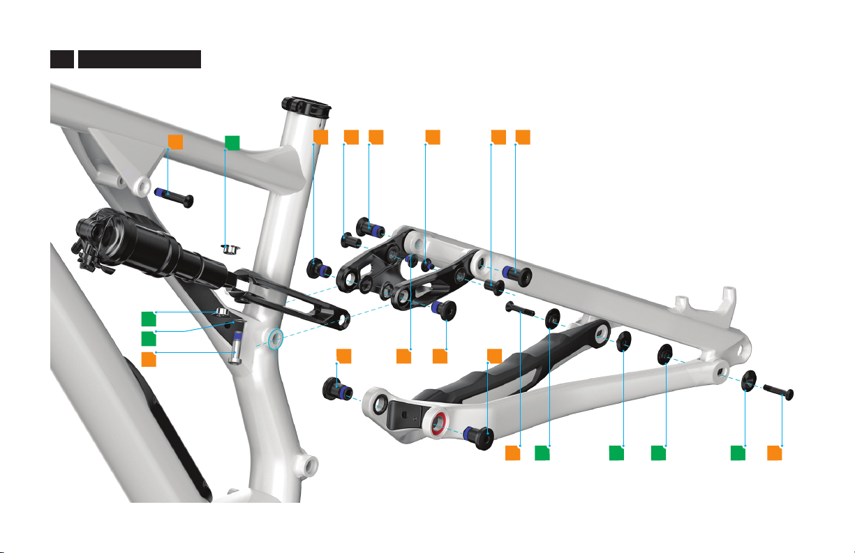
10
Q
SVP L PO L
U
V
TO Q
J K
D E F F E D
4.2 EXPLODED VIEW - BOLTS
11
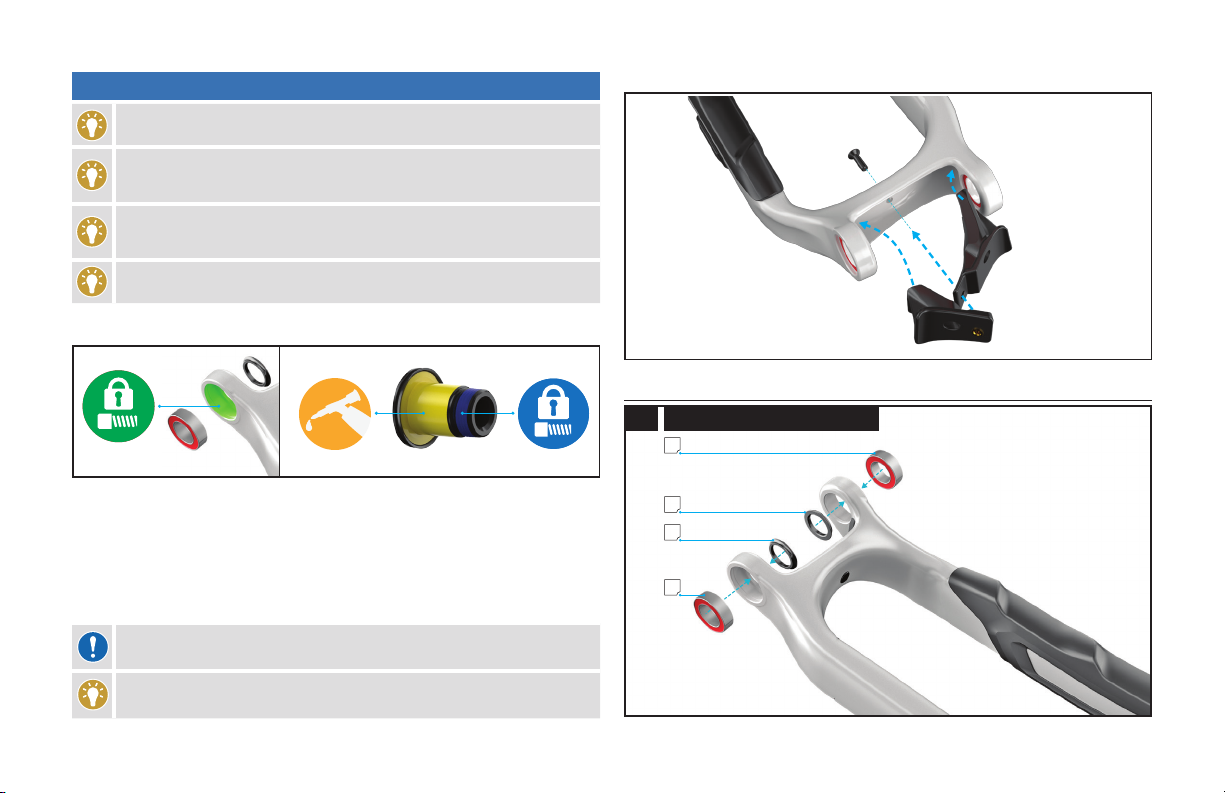
Before assembling pivots, install the two cable guides into the chain-stay.
5.1. BEARING ASSEMBLY
A
I
I
A
5.1 MAIN PIVOT BEARINGS AND SPACERS
5. REAR TRIANGLE PIVOT ASSEMBLY
Before attaching the rear triangle assembly, you may want to install the
seatpost ICR tube. Refer to section 6.1 DROPPER SEATPOST for instructions.
To successfully build the Stumpjumper Evo Alloy rear triangle, it is very
important to follow the order of operations as outlined in this manual.
Modifying the order of assembly will result in a longer build process.
To properly assemble the Stumpjumper Evo Alloy, always place the smaller
(tapered) surface of the spacer against the bearing and the wider surface against
the frame or stay.
Check the expiration date on your Loctite. Do not use expired Loctite.
Apply green Loctite 603 to all the bearing/bore interface surfaces, then press all the
bearings into their respective pivot locations.
Even though all pivot bolts are factory treated with a blue threadlocker band, make sure to
complete the following steps in this order:
Apply and spread a thin layer of liquid blue Loctite 243 on the threads of both main pivot
bolts (J and K).
Apply a small amount of liquid blue Loctite 243 to the starting threads in the frame.
Clean up any Loctite that drips into the un-threaded counterbore part of the frame.
Grease the non-threaded part of the bolt while being careful not to contaminate the Loctite.
CAUTION: Make sure it is a thin layer. Too much Loctite may prevent the bolt from
being removed easily later.
Install the bottom bracket after the rear triangle is assembled.
12
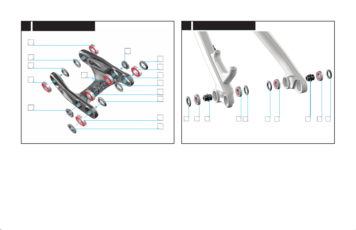
GCHCGGCHCG
5.3 HORST BEARINGS AND SPACERS
Fig. 5.3
Place the spacer into the bearing hole from the outer side of the chainstays.
Insert the bearings from both sides of the chainstay, sandwiching the spacer in the center.
N
M
B
B
M
M
B
B
M
R
B
R
B
N
N
5.2 LINK BEARINGS AND SPACERS

13
LINK @ SEAT TUBE
Q
QRR
5.5
Fig. 5.5
Place the link spacers against the link bearings (tapered surface against the bearing).
Grease the non-threaded part of the bolt, then thread the link bolts into the frame.
Use a 6 mm hex key to torque the bolts to 180 in-lbf / 20 Nm.
During assembly, place a folded paper towel or clean rag between the link and the
frame to prevent damage.
5.2. PIVOT ASSEMBLY
EXTENSION @ SHOCK
V
V
U
T
5.4
Fig. 5.4
Insert the top hat spacers into the rear shock eyelet.
Align the shock eyelet with the extension hole, then install the bolt.
Do not torque the lower shock eye-bolt until the last step!

14
FORWARD SHOCK EYELET BOLT
S
5.6
Fig. 5.6
Place the extension around the seat tube, then align the forward shock-eye with the frame
mount.
Insert the forward shock-eye bolt.
Use a 6 mm hex key to torque the bolts to 90 in-lbf / 10 Nm.
LINK @ EXTENSION
P
N
N
O
N
N
P
5.7
Fig.5.7
Grease, then place the extension spacers into the link bearings.
Align the extension with the extension bearings.
Grease, then insert the extension axles into the pivot bore.
Grease, then thread the extension bolts into the extension axles.
Use a 5 mm and 4 mm hex key to torque the bolts and axles to 60 in-lbf / 7 Nm.
15
SEATSTAY @ LINK
M
L
M
M
L
M
5.9
Fig. 5.9
Grease, then place the seatstay spacers (x4) against the link bearings (tapered surface
against the bearing).
Align the seatstay with the link bearings.
Grease the non-threaded part of the bolts, then thread the seatstay bolts (x2) into the
seatstay bores.
Use a 6 mm hex key to torque the bolts and axles to 180 in-lbf / 20 Nm.
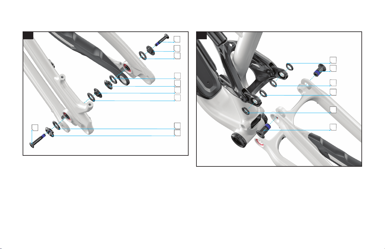
HORST LINK (DROPOUT)
D
D
E
G
G
F
F
G
G
E
5.8
Fig. 5.8
Grease, then place all the inner spacers (x4) against the Horst link bearings (tapered
surface against the bearing).
Align the flip chip spacers in either "high" or "low" position and place them against the
frame. The chainstay protector must be assembled prior to installation.
With the flip chips assembled, install the bolts. Make sure both drive-side and non-drive-
side flip chips are aligned in the same direction!
Use a 5 mm hex key to torque the bolts to 90 in-lbf / 10 Nm.
For instructions on adjusting the flip chip please see section 7.

16
MAIN PIVOT
K
IIJ
LH
5.10
Fig. 5.10
Place the main pivot spacers against the main pivot bearings (tapered surface against the
bearing).
Align the chainstay tabs with the main pivot bearings and spacers, then insert the pivot bolts.
Use a 6 mm hex key to torque the bolts to 210 in-lbf / 24 Nm.
The drive-side bolt is a left-hand thread.
LOWER SHOCK EYELET BOLT
T
5.11
Fig. 5.11
Once all pivot locations are assembled and torqued to specification, torque the lower
shock eyelet bolt.
Use a 6 mm hex key to torque the bolts to 180 in-lbf / 20 Nm.
When torqueing the rear shock eye bolt, use a long reach hex bit to avoid
damaging the paintwork.

17
6. INTERNAL ROUTING
For easier routing, the shock should be removed for side-arm cover access.
6.1. DROPPER SEATPOST
B
A
6.1
Fig. 6.1
Cut a section of ICR tube to the length specified per size via the table above.
Always route ICR tubes with housing inside to prevent kinking.
Carefully apply a small amount of Loctite 416 (or super glue) to the ICR tube (A) and attach
the cable guide (B).
Insert a section of scrap housing through the cable guide and ICR tube that is long enough
to reach from the headtube guide to the top of the seattube when routed through the frame.
5.3. SUSPENSION TORQUE SPECIFICATIONS
6
7
2
1
3
4
5
5.12
NON-DRIVE-SIDE
DRIVE-SIDE
# PIVOT LOCATION TOOL in-lbf Nm
1 MAIN PIVOT 6 mm HEX 210 24
2 LINK @ SEAT TUBE 6 mm HEX 180 20
3 LINK @ SEATSTAY 6 mm HEX 180 20
4 LINK @ EXTENSION 4 & 5 mm HEX 60 7
5 DROPOUT (HORST LINK) 5 mm HEX 90 10
6 FORWARD SHOCK EYE 6 mm HEX 90 10
7 REAR SHOCK EYE 6 mm HEX 180 20
Torque each pivot bolt according to the torque specification listed above.
NYLON ICR TUBE
SIZE LENGTH
S1 81 cm
S2 81 cm
S3 82 cm
S4 85.5 cm
S5 85.5 cm
S6 85.5 cm
Table of contents
Other StumpJumper Bicycle manuals


