EUFAB FIXbike e-Mobility User manual

1
DE FIXbike e-Mobility by EUFAB
DE GB FR
Art.-Nr. 14500
Inhalt
1. Bestimmungsgemäßer Gebraucht 2
2. Lieferumfang 2
3. Spezikationen 2
3.1 FIXbike 2
3.2 Motor 2
3.3 Batterie 2
3.4 Ladegerät 2
3.5 Steuerung 2
3.6 Elektrisches Schaltdiagramm, allgemein 3
3.7 Elektrisches Schaltdiagramm, Steuerung 3
4. Sicherheitshinweise 3
4.1 Allgemein 3
4.2 Ladegerät 4
4.3 Akku 4
5. Bedienungsanleitung 4
5.1 Montage 4
5.1.1 Montage des Lenkers 4
5.1.2 Montage der Pedale 4
5.1.3 Montage des hinteren Schutzblechs 4
5.1.4 Montage des Akkus 5
5.1.5 Montage der Frontleuchte 5
5.2 Übersicht 5
5.2.1 Allgemein 5
5.2.2 Lenker 6
5.2.3 Digitalinstrument 6
5.2.4 Fernbedienung 6
5.2.5 Ladegerät 6
5.2.6 Akku 6
5.3 Bedienung 6
5.3.1 Auaden des Akkus 6
5.3.2 Funktionen der Fernbedienung, Ein-/Ausschalten des FIXbikes 7
5.3.3 Klappmechanismus 7
5.3.4 Einstellen der Sattelhöhe 8
5.3.6 FIXbike abstellen 8
6. Wartung und Pege 8
6.1 Wartung und Pege 8
6.1.1 Reifendruck 8
6.1.2 Akku 9
6.1.3 Kette 9
6.1.4 Bremsen 9
6.1.5 Auswechseln der Batterien der Fernbedienung 9
6.2 Inspektions- undWartungsplan 9
6.3 Pege 10
7. Hinweise zum Umweltschutz 10
8. Kontaktinformationen 10
14500_ML-EAL-2017.indd 1 13.10.17 10:56

2
WARNUNG
Lesen Sie die Bedienungsanleitung vor Inbetriebnahme sorgfältig durch und beachten Sie alle Sicherheitshinweise!
Nichtbeachtung kann zu Personenschäden, Schäden am Gerät oder Ihrem Eigentum führen!
Bewahren Sie die Originalverpackung, den Kaufbeleg sowie diese Anleitung zum späteren Nachschlagen auf! Bei der Weitergabe
des Produkts geben Sie auch diese Anleitung weiter.
Prüfen Sie vor Inbetriebnahme den Inhalt der Verpackung auf Unversehrtheit und Vollständigkeit!
Technische Änderungen vorbehalten!
Das FIXbike ist für kurze Fahrten auf innerstädtischen, befestigten Straßen ausgelegt. Es eignet sich nicht für den Einsatz bei schlechten Straßenverhältnissen
undWetterbedingungen (z. B. Regen, Schnee oder vereiste Fahrbahn). Es kann nicht für Extremsportarten und Vorführungen verwendet werden.
Die Reichweite des FIXbikes wurde bei einer Außentemperatur von ca. 25 °C, mit ca. 70 kg Zuladung auf einer ebenen Fahrbahn gemessen. Sie kann je nach
Gewicht des Fahrers, Fahrverhalten, Außentemperatur und Fahrbahnzustand abweichen.
Dieses Gerät ist nicht dafür bestimmt, durch Kinder und Personen mit eingeschränkten geistigen Fähigkeiten oder ohne erforderliches Fachwissen benutzt zu
werden. Kinder sind von dem Gerät fernzuhalten.
Das Gerät ist nicht für den gewerblichen Einsatz bestimmt.
Zum bestimmungsgemäßem Gebrauch gehört auch die Beachtung aller Informationen in dieser Anleitung, insbesondere die Beachtung der Sicherheitshinwei-
se. Jede andere Verwendung gilt als nicht bestimmungsgemäß und kann zu Sach- oder Personenschäden führen. Die EAL GmbH übernimmt keine Haftung für
Schäden, die durch nicht bestimmungsgemäßen Gebrauch entstehen.
1. Bestimmungsgemäßer Gebrauch
2. Lieferumfang
1 x FIXbike
2 x Schlüssel
2 x Fernbedienung
1 x Ladegerät
1 x Batterie
2 x Pedal
1 x ansteckbare Frontleuchte
1 x Schutzblech hinten
1 x Schraubenschlüsselset
1 x Bedienungsanleitung
1 x Serviceheft
1 x Garantieformular
3.1 FIXbike
3.2 Motor
3.3 Batterie
3.4 Ladegerät
3.5 Steuerung
Radstand: 825 mm
L x B x H: ca. 1180 x 1100 x 550 [mm]
L x B x H (zusammengeklappt): ca. 1130 x 680 x 380 [mm]
Höchstgeschwindigkeit: 25 km/h
Max Reichweite: 40 km
Max. Belastung: 120 kg
Geräuschpegel: < 60 dB
Gewicht: ca. 21 kg
Nennspannung: 36V
Nennleistung: 250W
Rotor-Nenndrehzahl: 450 U / min
Max. Drehmoment: 28 Nm
Max. Ezienz: 80 %
Typ: bürsten- und getriebelos
Spannung: 36V
Kapazität: 8,7 Ah
Typ: Panasonic 18650 – 2900PF
Lebensdauer: über 1000 Ladezyklen
Entladungsrate: 3 C
Ladezeit: ca. 4 Stunden
Eingangsspannung: 230V
Ausgangsspannung: 42V
Ausgangsstrom: 2 A
Typ: Sinuswelle
Höchststrom: 14 A
Mindestspannung: 29V
3. Spezikationen
14500_ML-EAL-2017.indd 2 13.10.17 10:56

3
3.6 Elektrisches Schaltdiagramm, allgemein
3.7 Elektrisches Schaltdiagramm, Steuerung
4. Sicherheitshinweise
4.1 Allgemein
• DasWarndreieck kennzeichnet alle für die Sicherheit wichtigen Anweisungen. Befolgen Sie diese immer, anderenfalls könnten Sie sich verletzen
oder das Gerät könnte beschädigt werden.
• Kinder dürfen nicht mit dem Gerät spielen.
• Reinigung und Benutzerwartung dürfen nicht von Kindern ohne Beaufsichtigung durchgeführt werden.
• Lassen Sie dasVerpackungsmaterial nicht achtlos liegen. Dieses kann für Kinder zu einem gefährlichen Spielzeug werden!
• Benutzen Sie dieses Produkt nur für die dafür vorgeseheneVerwendung!
• Manipulieren oder zerlegen Sie das Gerät nicht!
• Verwenden Sie zu Ihrer eigenen Sicherheit ausschließlich Zubehör oder Ersatzteile, die in der Anleitung angegeben sind, oder derenVerwendung
durch den Hersteller empfohlen wird!
• Stellen Sie die Sattelhöhe so ein, dass Sie sicher und bequem fahren können und mit den Füßen schnell auf den Boden kommen.
14500_ML-EAL-2017.indd 3 13.10.17 10:56

4
Bild 1: Montage des Lenkers
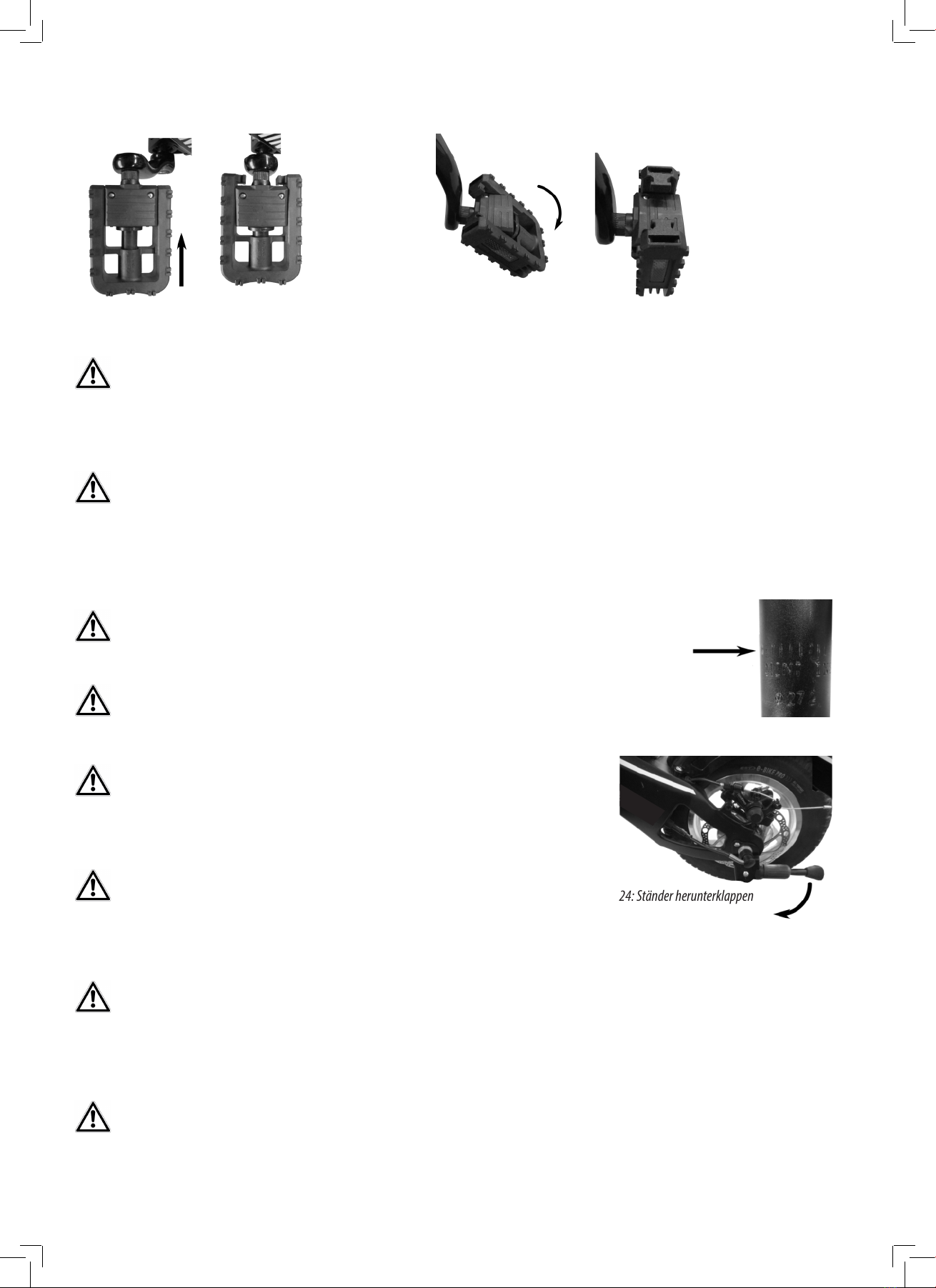
Bild 2: Kennzeichnung der Pedale
Bild 3: Schutzblech hinten
ACHTUNG: Die elektrischen Kabel und Bremsleitungen dürfen nicht verdreht,
geknickt oder eingeklemmt werden.
• Überzeugen Sie sich vor jedem Fahrtantritt davon, dass die Bremse funktioniert, der Reifendruck in Ordnung ist und dass sich alle Anbauteile in
einwandfreiem Zustand benden.
• Stellen Sie sicher, dass die Zubehörteile an den richtigen Stellen montiert wurden und machen Sie sich mit den Funktionen vertraut.
• Probieren Sie das FIXbike, wenn Sie es zum ersten Mal nutzen, zunächst auf einer kurzen, sicheren Strecke aus. Fahren Sie erst im Straßenverkehr,
wenn Sie das FIXbike gut beherrschen.
• Ein nicht ganz geschlossener Schnellspannhebel kann sich wieder önen. Dies kann zu schweren Stürzen führen. Das Umlegen des Schnellspann
hebels muss so schwer gehen, dass dafür der Handballen benötigt wird. Nur dann ist die Spannung stark genug.
• Tragen Sie immer einen Helm.
• Tragen Sie helle und auällige Kleidung. Achten Sie darauf, dass Sie keine weite Kleidung tragen, mit der Sie an der Kette, am Lenker, an den
Pedalen oder in den Rädern hängenbleiben können.
4.2 Ladegerät
4.3 Akku
• Betreiben Sie das Ladegerät nicht in feuchter oder nasser Umgebung.
• Vermeiden Sie unbedingt Wassereintritt in das Gerät. Falls doch Flüssigkeit eingetreten ist, trennen Sie das Ladegerät sofort vom Netz und lassen es von
Ihrem Fachhändler überprüfen.
• Stellen Sie das Ladegerät nur auf ebenen Flächen auf, sodass es sicher steht.
• Betreiben Sie das Ladegerät nicht mit beschädigtem Kabel oder Stecker.
• Betreiben Sie das Ladegerät nicht, nachdem es einen starken Schlag erhalten hat, fallengelassen oder sonst beschädigt wurde.
• Nehmen Sie keinen Reparaturversuch selbst vor. Önen oder zerlegen Sie das Gerät nicht. Lassen Sie das Ladegerät von Ihrem Fachhändler überprüfen.
• Vor einer Reinigung trennen Sie das Ladegerät vom Stromnetz und vom Akku.
• Das Ladegerät und der Akku des FIXbike sind aufeinander abgestimmt. Laden Sie den Akku niemals mit einem anderen Ladegerät.
• Schützen Sie den Akku vor Feuchtigkeit und harten Stößen.
• Nehmen Sie den Akku nicht in Betrieb, nachdem er einen starken Schlag erhalten hat, fallengelassen oder sonst beschädigt wurde.
• Nehmen Sie keinen Reparaturversuch selbst vor. Önen oder zerlegen Sie das Gehäuse des Akkus nicht. Lassen Sie den Akku von Ihrem Fachhändler
überprüfen.
• Berühren Sie die Kontakte des Akkus nicht mit metallischen Gegenständen.
• Lassen Sie den Akku bei längerem Nichtgebrauch auf keinen Fall dauernd am Ladegerät angeschlossen.
• Lassen Sie den Akku während des Ladevorgangs nicht unbeaufsichtigt.
5.1 Montage
5.1.1 Montage des Lenkers
5.1.2 Montage der Pedale
5.1.3 Montage des hinteren Schutzblechs
Der Lenker des FIXbike ist mit allenTeilen vormontiert und muss nur auf dem Steuerrohr
befestigt werden. Dazu lösen Sie die Schraube (A) und entfernen die Schutzkappe (C),
siehe Bild 1. Danach setzen Sie den Lenker auf das Steuerrohr.
Die Pedale sind gekennzeichnet, mit dem Buchstaben„R“ für die rechte und„L“ für die
linke Seite, siehe Bild 2. Das rechte Pedal besitzt ein Rechtsgewinde, das linke ein Links-
gewinde. Das rechte Pedal schrauben Sie im Uhrzeigersinn in der Gewindebohrung der
rechten Tretkurbel fest. Das linke Pedal schrauben Sie entgegen dem Uhrzeigersinn in
der Gewindebohrung der linkenTretkurbel fest.
Setzen Sie das Schutzblech auf den Rahmen vor dem Hinterrad. Richten Sie es zu den
Befestigungsbohrungen aus und schrauben Sie es mit den beiden Schrauben fest, Bild 3
Richten Sie den Lenker gerade aus und ziehen Sie die beiden Schrauben (B) fest an. Setzen Sie die Schraube (A) wieder in den Steuerkopf ein und ziehen Sie sie
fest.
5. Bedienungsanleitung
14500_ML-EAL-2017.indd 4 13.10.17 10:56

5
Bild 4: Önen der Verriegelung
Bild 8: Schließen der Verriegelung
Bild 9: Übersicht, allgemein
Bild 7: Akku montiertBild 6: Andrücken des AkkusBild 5: Einsetzen des Akkus
5.1.4 Montage des Akkus
5.1.4 Montage der Frontleuchte
5.2 Übersicht
5.2.1 Allgemein
Stecken Sie den Schlüssel in das Schloss auf der rechten Seite des Akkus und drehen Sie
ihn entgegen dem Uhrzeigersinn bis zum Anschlag, Bild 4. Die Verriegelung des Akkus
ist jetzt ganz geönet.
Stecken Sie die Frontleuchte mit der Blechlasche in die Halterung vorn am Steuerrohr des FIXbike. Schalten Sie die Frontleuchte ein und richten Sie sie so aus,
dass der Lichtkegel ca. 10 m vor dem FIXbike auf die Straße fällt. Schalten Sie die Frontleuchte wieder aus.
Drücken Sie den Akku am oberen Ende fest in die Halterung. Wenn der Akku Kontakt
mit dem elektrischen System des FIXbike hat, ertönt ein akustisches Signal. Halten Sie
den Akku dort fest. Drehen Sie den Schlüssel im Uhrzeigersinn bis zum Anschlag, Bild 8.
Ziehen Sie den Schlüssel ab. Der Akku ist jetzt fest verriegelt.
Setzen Sie jetzt den Akku in die Halterung, wie auf den folgenden Bildern, Bild 5 bis 7, gezeigt ein.
Achten Sie darauf, dass die Anschlüsse des Akkus während der Montage nicht
in Kontakt mit metallischen Gegenständen kommen. Es besteht Brand- und
Explosionsgefahr.
1 Vorderrad
2 Bremse vorn
3 Federgabel
4 Halter für Frontleuchte
5 Lenker
6 Sattel
7 Schnellverschluss Sattelverstellung
8 HebelVerriegelung Klappmechanimus
9 Akku
10 Rücklicht
11 Schutzblech hinten
12 Bremse hinten
13 Hinterrad mit Nabenmotor
14 Pedale
14500_ML-EAL-2017.indd 5 13.10.17 10:56

6
5.2.2 Lenker
5.2.3 Digitalinstrument
5.2.4 Fernbedienung
5.2.5 Ladegerät
5.2.6 Akku
5.3 Bedienung
5.3.1 Auaden des Akkus
Anschließen des Ladegerätes:
15 Bremsgri links, Hinterrad
16 Einstellschraube Hinterradbremse
17 EinstellschraubeVorderradbremse
18 Bremsgri rechts,Vorderrad
19 Glocke
20 Lichtschalter
21 Digitalinstrument
22 Geschwindigkeitsanzeige
23 Kilometerstand
24 Batterieanzeige
25 Fahrzeit
26 Außentemperatur
27 Kontrollleuchte
28 Einschalttaste Diebstahlwarnanlage
29 Ausschalttaste Diebstahlwarnanlage
30 Suchtaste Fahrzeug
31 Starttaste
32 Öse für Schlüsselring
33 Netzstecker
34 Ladestecker
35 Ladegerät
36 Kontrollleuchte
37 Schloß
38 Ladebuchse mit Schutzkappe
39 Rücklicht
40 Anschlüsse
41 Verriegelung
Der Akku kann in ein- oder ausgebautem Zustand aufgeladen werden. Schalten Sie das FIXbike aus (siehe dazu Abschnitt 5.3.2), wenn Sie den Akku in einge-
bautem Zustand auaden.
Entfernen Sie als erstes die Schutzkappe von der Ladebuchse (Position 38 in der Übersicht) auf der linken Seite des Akkus. Stecken Sie den Ladestecker (Position
34 in der Übersicht) in die Ladebuchse und ziehen Sie die Überwurfmutter des Steckers fest. Stecken Sie erst zuletzt den Netzstecker (Position 33 in der Über-
sicht) des Ladegerätes in die Steckdose.
Die Kontrollleuchte (Position 36 in der Übersicht) des Ladegerätes leuchtet während des Ladevorgangs rot. Wenn der Akku vollgeladen ist, schaltet die Kont-
rollleuchte auf grün.
Bild 10: Übersicht Lenker
Bild 11: Übersicht Digitalinstrument
Bild 12: Übersicht Fernbedienung
Bild 13: Übersicht Ladegerät
Bild 14: Übersicht Akku
14500_ML-EAL-2017.indd 6 13.10.17 10:56

7
Bild 15: Schnellverschluss
geschlossen
Bild 16: Schnellverschluss
geönet
Bild 17: Sattel gerade
Bild 19: Lösen der Verriegelung
Bild 18: Sattel gedreht
Bild 20: FIXbike
zusammengeklappt
Entfernen des Ladegerätes:
5.3.2 Funktionen der Fernbedienung, Ein-/Ausschalten des FIXbikes
Funktionen der Fernbedienung
Ein-/Ausschalten des FIXbikes
Aktivieren/Deaktivieren der Diebstahlwarnanlage
5.3.3 Klappmechanismus
Zusammenklappen des FIXbikes
Ziehen Sie zuerst den Netzstecker aus der Steckdose. Danach lösen Sie die Überwurfmutter des Ladesteckers und ziehen ihn aus der Ladebuchse des Akkus.
Bringen Sie die Schutzkappe wieder an. Halten Sie diese Reihenfolge immer ein.
JederTastendruck auf der Fernbedienung wird mit einem Aueuchten der Kontrollleuchte (Position 27 in der Übersicht) bestätigt.
Zum Einschalten des FIXbikes schalten Sie zuerst die Diebstahlwarnanlage aus (einmaliges Drücken der Ausschalttaste). Danach drücken Sie innerhalb von 3
Sekunden zweimal die Starttaste. Es ertönt ein akustisches Signal und das Digitalinstrument wird aktiviert. Das FIXbike ist jetzt fahrbereit.
Schalten Sie das FIXbike zuerst aus. Die Diebstahlwarnanlage aktivieren Sie, indem Sie die Einschalttaste einmal drücken. Es ertönt ein akustisches Signal.
Sie können die Empndlichkeit des Auslösesensors für die Diebstahlwarnanlage auf zwei Stufen einstellen: Hoch, sehr empndlich, Auslösen bei geringster
Bewegung des FIXbikes. Niedrig, zum Auslösen muss das FIXbike ein Stück geschoben werden. Diese Einstellungen nehmen Sie durch langes (2 Sekunden)
Drücken der Suchtaste vor.
Die Diebstahlwarnanlage wird deaktiviert, wenn Sie die Ausschalttaste einmal drücken.
Lösen Sie den Schnellspannverschluss (Position 6 in der Übersicht) der Sattelstütze und drehen Sie die Sattelspitze zur Seite (Bilder 15 bis 18). Verschließen Sie
den Schnellverschluss wieder.
Halten Sie das FIXbike mit einer Hand am Lenker fest. Mit der anderen Hand
drücken Sie den Hebel für dieVerriegelung (Bild 19) (Position 8 in der Über-
sicht) am Rahmen nach oben. Ziehen Sie nun den Rahmen nach oben und
lassen Sie den Hebel wieder los. Heben Sie den Rahmen mit der Sattelstütze
so weit an, bis dieVerriegelung hörbar einrastet.
Das FIXbike ist nun zusammengeklappt (Bild 20) und kann platzsparend ver-
staut oder transportiert werden.
Sie schalten das FIXbike aus, indem Sie die Ausschalttaste einmal drücken.
Einschalttaste
(Position 28 in der Übersicht)
Aktivieren der Diebstahlwarnanlage
einmal drücken
Einschalten des akustischen Alarms
2 Sekunden lang drücken
Ausschalttaste
(Position 29 in der Übersicht)
Deaktivieren der Diebstahlwarnanlage
einmal drücken
Ausschalten des akustischen Alarms
2 Sekunden lang drücken
Suchtaste
(Position 30 in der Übersicht)
akustisches Signal zum Finden des
Fahrzeugs
einmal drücken
Einstellen der Empfindlichkeit des
Sensors zum Auslösen der
Diebstahlwarnanlage (hoch/niedrig)
2 Sekunden lang drücken
Starttaste
(Position 31 in der Übersicht)
FIXbike einschalten 2 mal innerhalb von 3 Sekunden drücken
Tabelle 1: Funktionen der Fernbedienung
Schalten Sie das FIXbike immer zuerst aus, bevor Sie den Klappmechanismus betätigen.
14500_ML-EAL-2017.indd 7 13.10.17 10:56

8
Einklappen der Pedale
Auseinanderklappen des FIXbikes
5.3.4 Einstellen der Sattelhöhe
6. Wartung und Pege
6.1 Wartung
6.1.1 Reifendruck
Reifendruck vorn und hinten: max. 2,8 bar
5.3.5 FIXbike abstellen5.3.5 FIXbike abstellen
Sie können noch die Pedale des FIXbikes einklappen. Dies ist zum Beispiel hilfreich, wenn Sie das FIXbike in öentlichen Verkehrsmitteln mitnehmen wollen.
Gehen Sie dazu, wie auf den Bildern 21 und 22 dargestellt, vor.
Halten Sie das FIXbike mit einer Hand am Lenker fest. Mit der anderen Hand drücken Sie den Hebel für dieVerriegelung (Bild 19) am Rahmen nach oben. Halten
Sie den Hebel fest und drücken Sie den Rahmen mit der Sattelstütze nach unten. Auf halben Weg lassen Sie den Hebel los, und drücken den Rahmen in die
Fahr-Stellung bis dieVerriegelung wieder eingerastet ist. Stellen Sie den Sattel wieder gerade.
Um bequem und sicher fahren zu können, müssen Sie den Sattel auf Ihre Körpergröße einstellen.
Dazu önen Sie den Schnellverschluss an der Sattelstütze, (Bild 15). Stellen Sie die Sattelhöhe so ein, dass beim Sitzen der Fuß, bei nicht ganz durchgestrecktem
Bein, auf dem Pedal in der untersten Stellung auiegt. Sie sollten mit den Fußspitzen den Boden noch bequem berühren können. Drücken Sie den Hebel des
Schnellverschlusses wieder fest.
Parken Sie das FIXbike nicht ungeschützt im Freien. Vermeiden Sie direkte Sonneneinstrahlung oder Regen. Wenn Regenwasser in das Innere des FIXbikes
eindringt, kann es zu Kurzschlüssen und damit zu Zerstörung der Elektronik kommen.
Die Räder des FIXbikes sind mit Schraderventilen (Autoventilen) ausgestattet. Die Reifen können mit handelsüblichen Luftpumpen für dieseVentilart, aber auch
mit Kompressoren aufgepumpt werden.
Sollten Sie das FIXbike für einen längeren Zeitraum nicht benutzen, stellen Sie es so ab, dass die Reifen unbelastet sind.
Stellen Sie das FIXbike nur auf einem festen Untergrund ab (kein Sand, Kies oder sonstige lose Oberä-
chen). Klappen Sie den Ständer aus (Bild 24) und neigen Sie das FIXbike soweit, dass der Ständer den
Boden berührt. Kontrollieren Sie den sicheren Stand des FIXbike, bevor sie es loslassen.
Sie bringen das Pedal wieder in Fahrposition, indem Sie das äußere Ende anheben bis das Pedal einrastet.
Bild 22: Einklappen des Pedals
Bild 23: Markierung auf Sattelstütze
Bild 24: Ständer herunterklappen
Bild 21: Lösen der Verriegelung
Fassen Sie das Pedal immer nur außen an, nie in der Nähe derTretkurbel. Es besteht Quetschgefahr für die Finger.
Führen Sie nach der Reinigung bzw. vor Fahrtantritt eine Bremsprobe durch.
Bei der Verwendung von Kompressoren (z. B. an Tankstellen) wird aufgrund des kleinen Volumens, der maximale Fülldruck sehr schnell erreicht.
Stellen Sie sicher, dass der Schnellverschluss der Sattelstütze festsitzt und der Spannhebel ganz am Sattelrohr anliegt.
Ziehen Sie die Sattelstütze nur bis zu der Markierung, Striche, Bild 23, heraus.
Die Markierung darf nicht sichtbar sein!
Stellen Sie sicher, dass der Schnellverschluss der Sattelstütze festsitzt und der
Spannhebel ganz am Sattelrohr anliegt.
Schalten Sie das FIXbike immer zuerst aus, bevor Sie es abstellen.
Stellen Sie sicher, dass der Ständer vollständig hochgeklappt und eingerastet ist, bevor
Sie mit dem FIXbike losfahren. Ein heruntergeklappter Ständer kann während der Fahrt zu
schweren Stürzen führen.
Markierung für maximale
Sattelhöhe
14500_ML-EAL-2017.indd 8 13.10.17 10:56

9
Bild 25: Gehäuseschrauben
entfernen
Bild 26: Platine vorsichtig
aus dem Gehäuse nehmen
Bild 27: Batteriehalter
entfernen
Bild 28: Batterien in Batteriehalter einlegen
6.1.2 Akku
6.1.3 Kette
6.1.4 Bremsen
6.1.5 Auswechseln der Batterien der Fernbedienung
6.2 Inspektions- und Wartungsplan
Kontrollieren Sie regelmäßig den Ladezustand des Akkus durch Ablesen der Batterieanzeige im Digitalinstrument. Bei nur noch einem sichtbaren Ladebalken,
laden Sie den Akku wieder auf. Bei langem Nichtgebrauch, z. B. Winterpause, laden Sie den Akku alle drei Monate auf. Zur Wiederinbetriebnahmen nach einer
langen Pause lassen Sie den Akku ca. einen Tag am Ladegerät angeschlossen.
Schmieren Sie die Kette alle 500 km oder nach jeder Reinigung und nach jeder Regenfahrt mit einem Kettenschmiermittel aus dem Fahrradfachhandel. Kont-
rollieren Sie alle 500 km die Kettenspannung. Dazu heben Sie den rücklaufenden Teil der Kette in der Mitte an. Wenn sich die Kette mehr als fünf Kettenhöhen
anheben lässt ist die Kettenspannung zu gering und die Kette muß gespannt oder ersetzt werden.
Wenn die Leistungder Bremsennachlässt und Sie die Bremshebelsehr weit ziehen müssen,stellenSiedieBremsseiledurchHerausdrehen der Einstellschrauben
an den Bremshebeln nach.Wenn dies nicht mehr ausreicht um eine sichere Bremsleistung zu gewährleisten, suchen Sie eine Fahrradfachwerkstatt auf, um die
Bremse instand setzen zu lassen.
Zum Austausch werden zwei Knopfzellen, Typ CR2025, 3V, Lithium, benötigt. Önen Sie die Fernbedienung und tauschen Sie die Batterien aus, wie auf den
Bildern 25 bis 28 gezeigt.
Achten Sie beim Einsetzen der Batterien darauf, dass der Pluspol der Knopfzellen oben ist.
Der Zusammenbau erfolgt in umgekehrter Reihenfolge.
P = Prüfen, E = Ersetzen
*) siehe Kapitel 6.1.3
Inspektions- und Wartungsintervalle
Laufzeit in km
300
2000
4000
6000
elektr. Anlage, Beleuchtung
P
P
P
P
Reifendruck, Profiltiefe mindestens 1 mm
P
P
P
P
Federgabel, Dämpfung / Dichtheit
P
P
P
P
Akkuladespannung / Leistung prüfen
P
P
P
P
Akku auf Dichtigkeit prüfen
P
P
P
P
Bremszüge auf Beschädigungen prüfen
P
P
P
P
Bremsscheibe, Bremsbeläge vorne
P
P
P
P/E
Bremsscheibe, Bremsbeläge hinten
P
P
P
P/E
Glocke
P
P
P
P
Motor-Hauptkabel auf Beschädigung prüfen
P
P
P
P
Pedale / Lagerspiel
P
P
P
P
Elektromotor auf zentrische Montage prüfen
P
P
P/E
P/E
Festigkeit aller sicherheitsrelevanter Schrauben
P
P
P
P
Bremslichtschalter
P
P
P
P
Scheinwerfereinstellungen
P
P
P
P
Räder: Lagerspiel, Laufruhe
P
P
P
P
Reifen auf Beschädigungen und Fremdkörper prüfen
P
P
P
P/E
Lenkkopf-Lagerspiel, Lenker-Verschraubung
P
P
P
P
Tachoantrieb
P
P
P
P
Schmierstellen: Züge, Hebel, Bremsnocken, Seitenständer,
Schloßmechanismen, Kette *) P P P P
14500_ML-EAL-2017.indd 9 13.10.17 10:56

10
GB FIXbike e-Mobility by EUFAB
Article number 14500
Overview
1. Proper usage 11
2. Scope of supply 11
3. Specications 11
3.1 FIXbike 11
3.2 Motor 11
3.3 Battery 11
3.4 Charging unit 11
3.5 Controls 11
3.6 Electrical wiring diagram, general 12
3.7 Electrical wiring diagram, controls 12
4. Safety notes 12
4.1 General 12
4.2 Charging unit 13
4.3 Battery 13
5. Operating instructions 13
5.1 Assembly 13
5.1.1 Handlebar assembly 13
5.1.2 Pedal assembly 13
5.1.3 Rear mudguard assembly 13
5.1.4 Battery assembly 14
5.1.5 Front light assembly 14
5.2 Overview 14
5.2.1 General 14
5.2.2 Handlebars 15
5.2.3 Digital instrument 15
5.2.4 Remote control 15
5.2.5 Charging unit 15
5.2.6 Battery 15
5.3 Operation 15
5.3.1 Charging the battery 15
5.3.2 Remote contro functions, switching the FIXbikes on/o 16
5.3.3 Folding mechanism 16
5.3.4 Adjusting the seat height 17
5.3.6 Parking the FIXbike 17
6. Maintenance and care 17
6.1 Maintenance 17
6.1.1 Tyre pressure 17
6.1.2 Battery 18
6.1.3 Chain 18
6.1.4 Brakes 18
7. Hinweise zum Umweltschutz
8. Kontaktinformationen
Entsorgen Sie Elektrogeräte nicht mit dem Hausmüll! Elektro- und Elektronikaltgeräte müssen getrennt gesammelt und einer umweltgerechtenWie-
derverwertung zugeführt werden. Über Entsorgungsmöglichkeiten für Elektro- und Elektronikaltgeräte informieren Sie sich bei Ihrer Gemeinde- oder
Stadtverwaltung.
Am Ende ihrer Lebensdauer gehören Altbatterien und Altakkus keinesfalls in den Hausmüll – oder gar achtlos in die Umwelt. Geben Sie Altbatterien/
Altakkus zum Beispiel bei den Sammelstellen derVertreiber (Händler) ab. Sie leisten dadurch einen wertvollen Beitrag zum Umweltschutz.Teilweise
nehmen auch die Kommunen Altbatterien und Altakkus zurück, zum Beispiel über Schadstomobile oder auf Recyclinghöfen.
EAL GmbH
Otto-Hausmann-Ring 107
42115Wuppertal
Deutschland
6.3 Pege
Reinigen Sie das FIXbike niemals mit einem Hochdruckreiniger. Dadurch können die Reifen beschädigt und Dichtungen zerstört werden. Es kann
Wasser in Lager und die elektrische Anlage eindringen.
Verwenden Sie zum Reinigen nur handelsübliche Reinigungs- und Pegemittel für Fahrräder.Vermeiden Sie das Eindringen von Flüssigkeiten in das Innere der
elektrischen Anlage und des Digitalinstruments. Benutzen Sie für Kunststooberächen keine Poliermittel.
Telefon: +49 (0)202 42 92 83 0
Telefax: +49 (0)202 2 65 57 98
Internet: www.eal-vertrieb.com
E-Mail: info@eal-vertrieb.com
14500_ML-EAL-2017.indd 10 13.10.17 10:56

11
6.1.5 Replacing the remote control batteries 18
6.2 Inspection and service plan 18
6.3 Care 18
7. Environmental protection notes 19
8. Contact information 19
WARNING
Read through all operating instructions carefully before operating and observe all safety information!
Non-compliance can lead to personal injury, damage to the device or to your property!
Keep the original packaging, the purchase receipt as well as these instructions for future reference!When transferring this product
pass on these instructions as well.
Before operating, check that the content of the package is intact and complete!
Subject to technical changes!
The FIXbike is designed for short trips on paved roads in urban areas. It is not suitable for usage where road and weather conditions are bad (e.g. rain, snow or
icy roads). It cannot be used for extreme sports and demonstrations.
The range of the FIXbike is measured at an outdoor temperature of about 25 °C with a load of approx. 70 kg on a smooth road. This can deviate depending on
the weight of the driver, driving performance, outdoor temperature and road condition.
This device is not suitable to be used by children and people with reduced mental capacity or without the necessary specialised knowledge. Children should
keep away from the device.
This device is not intended for commercial usage.
Proper usage also includes observing all the information in these instructions, especially observance of the safety notes. Any other usage is considered improper
and can lead to property damage and personal injury. EAL GmbH is not liable for damages that occur due to improper usage.
1. Intended usage
2. Scope of supply
1 x FIXbike
2 x keys
2 x remote control
1 x charging unit
1 x battery
2 x pedals
1 x connectible front light
1 x back mudguard
1 x wrench set
1 x operating instructions
1 x service booklet
1 x warranty form
3.1 FIXbike
3.2 Motor
3.3 Battery
3.4 Charging unit
3.5 Controls
Wheelbase: 825 mm
L xW x H: approx. 1180 x 1100 x 550 [mm]
L xW x H (folded together): approx. 1130 x 680 x 380 [mm]
Maximum speed: 25 km/h
Max. range: 40 km
Max. load: 120 kg
Noise level: < 60 dB
Weight: approx. 21 kg
Nominal voltage: 36V
Rated power: 250W
Rotor rated speed: 450 U / min
Max. torque: 28 Nm
Max. eciency: 80 %
Type: brushless and gearless
Voltage: 36V
Capacity: 8.7 Ah
Model: Panasonic 18650 – 2900PF
Service life: over 1,000 loading cycles
Discharge rate: 3 C
Charging time: approx. 4 hours
Input voltage: 230V
Output voltage: 42V
Output current: 2 A
Model: Sine wave
Maximum current: 14 A
Minimum voltage 29V
3. Specications
14500_ML-EAL-2017.indd 11 13.10.17 10:56

12
3.6 Electrical wiring diagram, general
3.7 Electrical wiring diagram, controls
bold, red
bold, black
bold, blue
bold green
bold yellow
thin red
thin yellow
thin blue
thin green
thin black
thin red
thin blue
thin green
thin black
thin white
thin orange
thin blue
thin green
thin orange
thin black
thin violet
thin white
thin white
thin red
thin black
Battery
Battery
Speedo-
meter
Anti-theft
alarm
Charging unit
Charging
Connection
Battery +
Battery -
Measuring signal speed
Signal throttle valve
Brake signal
Brake signal
Lock ACC
Lock ACC
Lock motor CLK
Line phase detection
Battery – GND
Line FE1
Battery + ACC
GND
Energy Light
Brakes
Acoustic signal
generator
Switch
Warning light
horn
Throttle valve
LCD measuring
device
Maximum speed
Anti-theft alarm
Anti-theft alarm
Brake light
Reverb
Brake signal
thin orange
thin blue
thin green
thin orange
thin black
thin violet
thin white
thin white
thin red
thin black
bold, red
bold, black
bold, blue
bold green
bold yellow
Battery
Battery +
Battery -
Measuring signal speed
Signal throttle valve
Brake signal
GND
Energy
Lock ACC
Lock motor CLK
Phase detection line
Line FE1
Battery + ACC
Battery – GND
Lock ACC
Brake signal
thin red
thin blue
thin green
thin black
thin white
LCD measuring device
Maximum speed
Anti-theft alarm
Anti-theft alarm
Brake light
thin red
thin yellow
thin blue
thin green
thin black
red
yellow green blue
black
Reverb
4. Safety information
4.1 General information
• The warning triangle identies all instructions that are important for safety. Be sure to always follow these, otherwise you could injure yourself or
damage the device.
• Children are not allowed to play with the device.
• Cleaning and user maintenance cannot be performed by children without supervision.
• Do not leave the packaging material lying around. It can be a dangerous toy for children!
• Only use this product for its intended purpose!
• Do not tamper with or disassemble the device!
• For your own safety, only use accessories or replacement parts that are listed in the instructions or the usage of which is recommended by the
manufacturer!
• Adjust the seat height so that you can ride safely and comfortably and are able to place feet on the ground quickly.
14500_ML-EAL-2017.indd 12 13.10.17 10:56

13
• Before each ride, ensure that the brakes function, the tire pressure is ok, and that all xtures are in faultless condition.
• Ensure that accessory parts are mounted at the right positions and familiarise yourself with the functions.
• When using the FIXbike for the rst time, rst try it out on a short, safe section of road. Only drive in road trac when you have good control riding the
FIXbike.
• A quick-release lever that isn‘t completely closed can re-open. This can lead to serious falls.Turning the quick-release lever must be so dicult that the
heel of the hand is required to do so. Only then is the tension strong enough.
• Always wear a helmet.
• Wear bright and noticeable clothing. Be sure not to wear loose clothing that could get stuck in the chain, handlebars, pedals or wheels.
Image 1: Assembling the handlebars
Image 2: Labelling on the pedals
Image 3: Back mudguard
ATTENTION: The electrical cables and brake lines cannot be twisted, kinked
or clamped.
4.2 Charging unit
4.3 Battery
• Do not use the charging unit in a moist or wet environment.
• Be sure to prevent water from penetrating the device. If liquid should get inside, immediately separate the charging unit from the power supply and
have it checked by an authorised dealer.
• Place the charging unit on an even surface only so that it stands rmly.
• Do not operate the charging unit with damaged cable or plug.
• Do not operate the charging unit after it has received a strong hit, has fallen or been damaged in any other way.
• Do not attempt to repair the device yourself. Do not open or disassemble the device. Have the charging unit checked by your authorised dealer.
• Before cleaning, separate the charging unit from the power supply and from the battery.
• The FIXbike‘s charging unit and battery are mutually compatible. Never charge the battery using a dierent charging unit.
• Protect the battery from moisture and hard impacts.
• Do not use the battery after it has received a strong hit, has fallen or been damaged in any other way.
• Do not attempt to repair the device yourself. Do not open or disassemble the casing of the battery. Have the battery checked by your authorised dealer.
• Do not touch the battery contacts with metal objects.
• Never leave the battery permanently connected to the charging device when not in use for a long period of time.
• Do not leave the battery unattended during the charging procedure.
5.1 Assembly
5.1.1 Handlebar assembly
5.1.2 Pedal assembly
5.1.3 Rear mudguard assembly
The handlebars of the FIXbike are pre-assembled and just need to be attached to the
head tube. Do to so, loosen the screw (A) and remove the protective cap (C), see Image
1. Place the handlebars onto the head tube.
The pedals are marked with the letter„R“ for the right and„L“ for the left side, see Image
2. The right pedal has a right-hand thread, the left one has a left-hand thread. Screw
the right pedal clockwise into the threaded hole of the right pedal crank. Screw the left
pedal counter-clockwise into the threaded hole of the left pedal crank.
Place the mudguard on the frame of the back wheel. Align it with the mounting holes
and screw it tight with both screws, Image 3.
Straighten the handlebars and tighten both screws (B). Place the screw (A) back in the control head and tighten it.
5. Operating Instructions
14500_ML-EAL-2017.indd 13 13.10.17 10:56

14
Image 4: Opening the locking mechanism
Image 8: Closing the locking mechanism
Image 9: Overview, general
Image 7: Battery assembledImage 6: Pressing the batteryImage 5: Inserting the battery
5.1.4 Battery assembly
5.1.4 Front light assembly
5.2 Overview
5.2.1 General Information
Insert the key into the lock on the right side of the battery and turn in a counter-clockwi-
se motion as far as it will go, Image 4.The battery locking mechanism is now completely
open.
Insert the front light into the mount on the front of the FIXbike‘s head tube using the sheet metal tabs. Switch the front light on and adjust it so that the light
beam shines onto the street approx. 10 m in front of the FIXbike.Turn the front light o again.
Press the battery rmly into the mount at the top end.When the battery makes contact
with the FIXbike‘s electrical system, an acoustic signal will sound. Hold the battery there
rmly. Turn the key clockwise as far as it will go, Image 8. Remove the key. The battery
is now rmly locked.
Now put the battery into the mount as depicted in the following images, Image 5 to 7.
Ensure that the battery connections do not come into contact with metal
objects during assembly. It may cause a re and explosion hazard.
1 Front wheel
2 Front brakes
3 Suspension fork
4 Mount for front light
5 Handlebars
6 Seat
7 Quick-lock seat fastener
8 Locking lever, folding mechanism
9 Battery
10 Rear light
11 Back mudguard
12 Back brake
13 Back wheel with hub motor
14 Pedals
14500_ML-EAL-2017.indd 14 13.10.17 10:56

15
5.2.2 Handlebars
5.2.3 Digital instrument
5.2.4 Remote control
5.2.5 Charging unit
5.2.6 Battery
5.3 Operation
5.3.1 Charging the battery
Connecting the charging unit:
Removing the charging unit:
15 Brake handle, back wheel
16 Adjusting screw, back wheel brake
17 Adjusting screw, front wheel brake
18 Brake handle right, front wheel
19 Bell
20 Light switch
21 Digital instrument
22 Speed display
23 Mileage
24 Battery display
25 Travel time
26 Outside temperature
27 Control light
28 Anti-theft alarm on switch
29 Anti-theft alarm o switch
30 Vehicle search button
31 Start button
32 Eyelet for keyring
33 Power plug
34 Charging plug
35 Charging unit
36 Control light
37 Lock
38 Charging socket with protective cap
39 Rear light
40 Connections
41 Locking mechanism
The battery can be charged in an installed and uninstalled state. Switch the FIXbike o (see Section 5.3.2) when charging the battery that is not installed.
First remove the protective cap from the charging socket (Position 38 in the overview) on the left side of the battery. Plug the charging plug (Position 34 in the
overview) into the charging socket and tighten the plug‘s cap nut. Lastly, plug the power plug (Position 33 in the overview) of the charging unit into the socket.
First pull the power plug out of the socket.Then loosen the cap nut of the charging plug and pull it out of the battery‘s charging socket. Reattach the protective
cap. Always observe this sequence.
The control light (Position 36 in the overview) of the charging unit lights up while the battery is charging. When the battery is full, the control light turns green.
Image 10: Handlebars overview
Image 11: Digital instrument overview
Image 12: Remote control overview
Image 13: Charging unit overview
Image 14: Battery overview
14500_ML-EAL-2017.indd 15 13.10.17 10:56

16
Image 15: Quick-lock
closed
Image 16: Quick-lock
open
Image 17: Seat straight
Image 19: Releasing the locking
mechanism
Image 18: Seat turned
Image 20: Folded FIXbikes
5.3.2 Remote control functions, switching the FIXbikes on and o
Remote control functions
Switching the FIXbikes on/o
Activating/Deactivating the anti-theft alarm system
5.3.3 Folding mechanism
Folding the FIXbikes
The control light (Position 27 in the overview) lights up each time a remote control button is pressed.
In order to switch on the FIXbikes, rst switch the anti-theft alarm system o (press the o switch once).Then press the start button twice within 3 seconds. An
acoustic signal is heard and the digital instrument is activated.The FIXbike is now ready to be ridden.
First, switch the FIXbikes o. Press the on switch once to activate the anti-theft alarm system. An acoustic signal will sound.
You can set the sensitivity of the triggering sensor for the anti-theft alarm system to two levels: High, very sensitive, triggered at the slightest movement of the
FIXbike. Low, in order to be triggered the FIXbike must be moved away from its spot.These settings are selected by pressing the search button for 2 seconds.
Press the o switch once to deactivate the anti-theft alarm system.
Loosen the quick-release mechanism of the seat post (Position 6 in the overview) and turn the seat tip to the side (Image 15 to 18). Then lock the quick-lock
again.
HoldtheFIXbikesrmlywithone hand onthehandlebars.Usetheotherhand
to push the locking lever (Image 19) (Position 8 in the overview) upwards on
the frame. Now pull the frame upwards and release the lever. Lift the frame
with the seat post until the locking mechanism audibly clicks into place.
The FIXbikes has now been folded (Image 20) and can be stowed away to
save space or be transported.
Turn the FIXbikes o by pressing the o switch once.
On switch
(Position 28 in the overview)
Activating the anti-theft alarm system
press once
Switching on the acoustic alarm
press for 2 seconds
Off switch
(Position 29 in the overview)
Deactivating the anti-theft alarm system
press once
Switching off the acoustic alarm
press for 2 seconds
Search button
(Position 30 in the overview)
Acoustic signal to find the vehicle
press once
Set the sensitivity of the sensor that
triggers the anti-theft alarm (high/low)
press for 2 seconds
Start button
(Position 31 in the overview) Turn on the FIXbikes press 2 times in 3 seconds
Chart 1: Remote control functions
First switch the FIXbikes o before actuating the folding mechanism.
14500_ML-EAL-2017.indd 16 13.10.17 10:56

17
Folding the pedals
Unfolding the FIXbikes
5.3.4 Adjusting the seat height
6. Maintenance and care
6.1 Maintenance
6.1.1 Tyre Pressure
5.3.5 Parking the FIXbike
You can still fold the FIXbike‘s pedals.This can be helpful when you want to take the FIXbike onto public transportation. Proceed as depicted in Images 21 and 22.
Hold the FIXbike rmly with one hand on the handlebars. Use the other hand to push the locking lever (Image 19) upwards on the frame. Hold the lever rmly
and press the frame with the seat post downward. Let go of the lever halfway down and press the frame into riding position until the locking mechanism clicks
back into place. Straighten the seat again.
To ride comfortably and safely, the seat must be set to t your body size.
To adjust the height, open the quick-lock on the seat post (Image 15). Set the seat at a height where the foot rests on the pedal on the lowest position while
sitting with the leg not fully straight. You should be able to comfortably touch the oor with the tips of your feet. Press the quick-lock lever until tight again.
Do not park the FIXbike outdoors unprotected. Avoid direct sunlight or rain. Rainwater permeating the interior of the FIXbike can lead to short circuits thereby
destroying the electronics.
The wheels of the FIXbike are outtted with Schrader valves (car tyre valves).The tyres can be inated using a conventional air pump for this type of valve, or
with compressors.
Only park the FIXbike on a rm surface (no sand, gravel or other loose surfaces). Fold out the stand
(Image 24) and lean the FIXbike until the stand touches the ground. Check that the FIXbike stands
securely before letting go of it.
Put the pedal back into riding position by lifting the outer end until the pedal clicks into place.
Image 22: Folding the pedal
Image 23: Markings on the seat post
Image 24: Folding down the stand
Image 21: Releasing the locking mechanism
Always take hold of the pedal from the outside, never close to the pedal crank.There is a risk of ngers getting crushed.
Perform a brake test after cleaning and/or before starting a trip.
When using compressors (e.g. at a gas station) the maximum lling pressure is quickly attained due to the small volume.
Ensure that the seat post quick-lock sits rmly and the tension lever is at against the seat tube.
Only pull the seat post out up to the marking, lines, Image 23.The marking cannot be
visible!
Ensure that the seat post quick-lock sits rmly and the tension lever is at against the
seat tube.
First switch the FIXbike o before parking it.
Ensure that the stand is completely folded up and clicked in place before riding away in the
FIXbike. A folded-down stand can lead to serious falls while riding.
Marking for maximum
seat height
Tyre pressure front and back: max. 2.8 bar
If you aren‘t using the FIXbike for a longer period of time, park it in such a way that the tyres are unencumbered.
14500_ML-EAL-2017.indd 17 13.10.17 10:56

18
Image 25: Remove
casing screws
Image 26: Carefully remove
circuit board from the casing
Image 27: Remove battery
holder
Image 28: Place batteries into the battery
holder
6.1.2 Battery
6.1.3 Chain
6.1.4 Brakes
6.1.5 Changing remote control batteries
6.2 Inspection and service plan
Control the charge level of the battery regularly by reading the battery display in the digital instrument. If only one charging bar is visible re-charge the battery.
In the event of longer periods of non-use, e.g. winter break, charge the battery every three months.When starting to use the FIXbike after a long break, connect
the battery to the charging device for approx. one day.
Lubricate the chain every 500 km or after each cleaning and after every ride in the rain with a chain lubricant from a specialised bike shop. Check the chain
tension every 500 km. To do this, lift the returning part of the chain in the middle. If the chain can be lifted more than the height of ve chain links, the chain
tension is too low and the chain must be tightened or replaced.
If the performance of the brakes decreases and you have to pull the brake handle very far, readjust the brake cables by untwisting the adjusting screw on the
brake lever.When this is no longer enough to guarantee safe braking performance, nd a specialised bike workshop to repair the brakes.
Two button batteries,Type CR2025, 3V, lithium, are needed for replacement. Open the remote control and switch the batteries as depicted in Images 25 to 28.
When inserting the battery ensure that the positive terminal of the button batteries is on top.
Assembly is performed in reverse sequence.
C = Check, R = Replace
*) see Chapter 6.1.3
Inspection and service intervals
Runtime in km 300 2000 4000 6000
Electr. system, lighting
C
C
C
C
Tyre pressure, tread depth at least 1 mm
C
C
C
C
Suspension fork, shock absorption / impermeability
C
C
C
C
Battery charging voltage C C C C
Check battery for impermeability
C
C
C
C
Check brake cables for damage
C
C
C
C
Brake disk, brake pad front C C C C/R
Brake disk, brake pad back
C
C
C
C/R
Bell
C
C
C
C
Check main motor cable for damage
C
C
C
C
Pedal / bearing play
C
C
C
C
Check that the electric motor is centrally mounted
C
C
C/R
C/R
Tightness of all screws relevant for safety
C
C
C
C
Brake light switch
C
C
C
C
Headlight settings
C
C
C
C
Wheels: Bearing play, smooth operation
C
C
C
C
Check tyres for damage and foreign objects
C
C
C
C/R
Steering head bearing play, handlebar screws
C
C
C
C
Speedometer
C
C
C
C
Lubrication areas: Lines, levers, brake cams, side stands, locking
mechanisms, chain *)
C C C C
6.3 Care
Never clean the FIXbike with a high-pressure cleaner. This can damage the tyres and destroy seals. Water can permeate the bearings and the electric
system.
Use conventional cleaning and care products for bikes when cleaning. Prevent penetration of liquid into the interior of the electrical system and into the digital
instrument. Do not use a polishing product for the plastic surfaces.
14500_ML-EAL-2017.indd 18 13.10.17 10:56

19
7. Notes about environmental protection
8. Contact information
Never dispose of electrical devices in household waste! Electrical and electronic devices must be collected and brought in for environmentally compa-
tible recycling. Ask your municipality or city administration for disposal options for electrical and electronic devices.
At the end of their service lives, old batteries cannot be disposed of in household waste - or carelessly in the environment. Hand in old batteries at
distributor (dealer) collection points. By doing so you are making a valuable contribution to protecting the environment. Municipalities partially take
back old batteries, for instance through waste collection vehicles or at recycling yards.
EAL GmbH
Otto-Hausmann-Ring 107
42115Wuppertal
Germany
Telephone: +49 (0)202 42 92 83 0
Fax: +49 (0)202 2 65 57 98
Internet: www.eal-vertrieb.com
E-Mail: info@eal-vertrieb.com
FR FIXbike e-Mobility by EUFAB
N° d‘art. 14500
Sommaire
1. Domaine d‘application 20
2. Matériel fourni 20
3. Spécications 20
3.1 FIXbike 20
3.2 Moteur 20
3.3 Batterie 20
3.4 Appareil de recharge 20
3.5 Commande 20
3.6 Schéma de connexion électrique, généralités 21
3.7 Schéma de connexion électrique, commande 21
4. Consignes de sécurité 21
4.1 Généralité 21
4.2 Appareil de recharge 22
4.3 Batterie 22
5. Notice d‘utilisation 22
5.1 Montage 22
5.1.1 Montage du guidon 22
5.1.2 Montage des pédales 22
5.1.3 Montage du garde-boue arrière 22
5.1.4 Montage de la batterie 23
5.1.5 Montage du feu avant 23
5.2 Vue d‘ensemble 23
5.2.1 Généralités 23
5.2.2 Guidon 24
5.2.3 Instrument numérique 24
5.2.4 Commande à distance 24
5.2.5 Appareil de recharge 24
5.2.6 Batterie 24
5.3 Utilisation 24
5.3.1 Chargement de la batterie 24
5.3.2 Fonction de la commande à distance, allumer/éteindre le FIXbikes 25
5.3.3 Mécanisme de pliage 25
5.3.4 Réglage de la hauteur de la selle 26
5.3.6 Garer le FIXbike 26
6. Entretien et soins 26
6.1 Entretien 26
6.1.1 Pression des pneus 26
6.1.2 Batterie 27
6.1.3 Chaîne 27
6.1.4 Freins 27
6.1.5 Remplacement des piles de la commande à distance 27
6.2 Plan d‘inspection et d‘entretien 27
6.3 Nettoyage 28
7. Remarques relatives à la protection de l‘environnement 28
8. Données de contact 28
14500_ML-EAL-2017.indd 19 13.10.17 10:56

20
AVERTISSEMENT
Avant la mise en service, lisez attentivement la notice d‘utilisation et observez toutes les consignes de sécurité !
Tout non-respect de ces consignes peut entraîner des dommages corporels, endommager l‘appareil ou vos biens !
Conservez l‘emballage d‘origine, le justicatif d‘achat et la présente notice pour vous y référer ultérieurement ! Si vous revendez ou
remettez le produit à des tiers, veuillez également leur remettre cette notice d‘utilisation.
Avant la mise en service, vériez que le contenu de l‘emballage n‘est pas endommagé et vériez si toutes les pièces sont présentes !
Sous réserve de modications techniques !
Le FIXbike est conçu pour des trajets courts dans des routes urbaines stables et goudronnées. Il convient à une utilisation dans des mauvaises conditions routiè-
res et météorologiques (par exemple, de la pluie, de la neige ou une chaussée verglacée). Il ne peut pas être utilisé pour les types de sports extrêmes ou dans
des représentations.
La portée du FIXbike a été mesurée avec une température extérieure d‘env. 25 °C et avec env. 70 kg de charge sur une route plate. Elle peut varier en fonction du
poids du conducteur, de la conduite, de la température extérieure et de l‘état de la route.
Cet appareil n‘est pas destiné à être utilisé par des enfants ou des personnes aux capacités mentales limitées ou ne disposant pas de l‘expérience ou des connais-
sances nécessaires. Les enfants doivent rester à distance de cet appareil.
L‘appareil n‘est pas destiné à une utilisation industrielle ou commerciale.
L‘utilisation conforme aux prescriptions implique également le respect de toutes les informations contenues dans ce mode d‘emploi, en particulier le respect des
consignes de sécurité.Toute autre utilisation est considérée comme non conforme et risque d‘entraîner des dommages matériels ou corporels. EAL GmbH décline
toute responsabilité pour les dommages résultant d‘une utilisation non conforme.
1. Domaine d‘application
2. Matériel fourni
1 x FIXbike
2 x Clé
2 x Commande à distance
1 x Appareil de recharge
1 x Batterie
2 x Pédale
1 x Feu avant embrochable
1 x Garde-boue arrière
1 x Set de clé à molette
1 x Notice d‘utilisation
1 x Manuel de service
1 x Formulaire de garantie
3.1 FIXbike
3.2 Moteur
3.3 Batterie
3.4 Appareil de recharge
3.5 Commande
Empattement : 825 mm
L x l x H : env. 1180 x 1100 x 550 [mm]
L x B x H (replié) : env. 1130 x 680 x 380 [mm]
Vitesse maximale : 25 km/h
Portée max. : 40 km
Charge admise max. : 120 kg
Niveau sonore : < 60 dB
Poids : env. 21 kg
Tension nominale : 36V
Puissance nominale : 250 W
Couple nominal du rotor : 450 U / min
Couple max. : 28 Nm
Ecacité max. : 80 %
Type : sans brosses ni engrenages
Tension : 36V
Capacité : 8,7 Ah
Type : Panasonic 18650 – 2900PF
Durée de vie : plus de 1000 cycles de chargement
Taux de décharge : 3 C
Temps de charge : env. 4 heures
Tension d‘entrée : 230V
Tension de sortie : 42V
Courant de sortie : 2 A
Type : Onde sinusoïdale
Courant maximum : 14 A
Tension minimum : 29V
3. Spécications
14500_ML-EAL-2017.indd 20 13.10.17 10:56
This manual suits for next models
1
Table of contents
Languages:
Popular Bicycle manuals by other brands

Huffy
Huffy Mountain Bikes owner's manual

Diamondback
Diamondback Single-Speed Bicycle owner's manual

Derby cycle
Derby cycle Impulse 2.0 pedelec owner's manual

HNF-NICOLAI
HNF-NICOLAI XD2 Urban Rohloff Pedelec manual

EcoSpeed
EcoSpeed Electric Mid-Drive installation instructions

organic transit
organic transit ELF owner's manual