STW AUDIO REFLEX-PRO-X User manual

1
REFLEX-PRO-X
Manual
TRUE STEREO 4 CHANNEL MULTI DELAY/FX PLUG IN
Features:
•4 in ivi ual stereo elay channels with inter fee back an input routings
•3 effect slots for each channel.
•4 elay mo es
•22 selecte customizable effects with countless combination possibilities
•Extensive mo ulation options
•10 mo ulation sources of three ifferent types
•Mo ulation source logic
•Master FX section
© 2020-2021 Stefan Weyel www.stw-audio.com info@stw-audio.com doc version 1.2.0

2
Content
REGISTERING................................................................................................3
OPTIONS.......................................................................................................4
GENERAL......................................................................................................4
MAIN SECTION..............................................................................................5
MULTI DISPLAY SECTION............................................................................6
TOP DISPLAY................................................................................................7
SLOT SETTINGS............................................................................................8
MASTER EFFECT..........................................................................................8
MASTER SETTINGS.....................................................................................10
FEEDBACK MATRIX....................................................................................11
DELAY MODES............................................................................................11
TAP EDIT PAGE..........................................................................................15
DSP EFFECTS..............................................................................................17
PRE/POST EFFECTS...................................................................................17
FEEDBACK EFFECTS.................................................................................. 6
LFO.............................................................................................................. 7
ARPEGGIATOR/TRANCEGATE................................................................... 8
ENVELOPE GENERATOR............................................................................ 9
MODULATION LOGIC..................................................................................31
© 2020-2021 Stefan Weyel www.stw-audio.com [email protected] doc version 1.2.0

3
_______________________________
REGISTERING
'DEMO MODE' DISPLAY
REFLEX-PRO-X runs in Demo Mode until it's unlocked with a valid serial number and a re istration name. While in
Demo Mode the Parameter Display shows “DEMO MODE” and the Value display “REGISTER”.
Every one minute the input will be muted and the Parameter Display shows a blinkin “INPUT MUTED”
To enter the re istration pa e click on “REGISTER”
REGISTER PAGE
To unlock REFLEX-PRO-X you have to enter a valid re istration name and a serial number into the correspondin fields.
Both are sent to you in a re istration doc after purchasin REFLEX-PRO-X.
Thou h it's not recommended you can enter the data manually. More secure and convenient is to copy and paste the
data by keyboard shortcuts or much easier, use the paste buttons alon side the input fields.
After enterin your data push the “VALIDATE” button. If the validation succeeds the red icon behind “License key
activated” chan es to reen and a license file will be saved..
A click on the “CLOSE” button brin s you back to the main REFLEX-PRO-X Interface.
© 2020-2021 Stefan Weyel www.stw-audio.com [email protected] doc version 1.2.0

4
_______________________________
OPTIONS
The options pa e provides access to the colour-set selection. Chan e the actual colour settin s with a click on the
arrows or throu h the pop up menu which opens with a click on the colour-set name. The selected colour set will be
saved individually for every REFLEX-PRO-X instance.
Beside applyin just a visual preference, different colour settin s could come in handy to distin uish multiple instances of
REFLEX-PRO-X in the same project. A preview of the applied colours is displayed ri ht to the colour-set name.
_______________________________
GENERAL
Knob operation:
Double click on a knob sets the default value. Dra in a knob while holdin the shift key allows fine value chan es.
© 2020-2021 Stefan Weyel www.stw-audio.com [email protected] doc version 1.2.0

5
Modulation:
All knobs in the MULTI DISPLAY AREA with a reyed or darker center circle, as well as all MAIN SECTION parameters
provide modulation capabilities. Ri ht click - alternatively SHIFT+left double click - the center of a knob to brin up a
Drop down menu for modulation source selection. If a modulation source is active click&dra in the mouse in the center
area of the knob sets the modulation amount. Click & dra in outside the center area sets the ori inal parameter. If a
modulation source is set it will be indicated by a correspondin icon and the mod source representin color.
Slot design:
REFLEX-PRO-X contains 4 individual slots with identical parameter selections. All described parameters for the
MAIN/DELAY and EFFECT SECTIONS as well as the SLOT SETTINGS are available for each slot.
_______________________________
MAIN SECTION
ON: Enable/Disable slot.
INPUT: Slot input source. All slots have the options Mono[M], Left[L], Ri ht[R], Stereo[ST],
MasterFX output[FX]. Additionally slots 2 and hi her provide inputs from sin le or combinations of
previous slots. The routin is determined by the direct out settin of the selected slots.
GAIN: Input level [-inf dB - +12dB].
PAN: Panorama [100% L – 100% R].
FEEDBACK: Delay Feedback [0% - 160%].
LEVEL: Output level [-inf dB - +12dB]
MASTER FX: Master FX send level [0% - 100%]
All Main Section parameters can be modulated by one of 14 sources. Please refer to the section Modulation.
© 2020-2021 Stefan Weyel www.stw-audio.com [email protected] doc version 1.2.0

6
_______________________________
MULTI DISPLAY SECTION
Page selector
Click on one of the pa e titles to open the associated pa e display.
Available pa es are:
•Feedback Matrix [FB MATRIX]
•Pre Delay Effect Section [PRE-FX]
•Delay Section [DELAY]
•Delay Feedback Effect Section [FB-FX]
•Post Delay Effect Section [POST-FX]
•Slot Settin s [SLOT]
•Low Frequency Oscillators [LFO]
•Arpe iator/TranceGate [GATE]
•Envelope Generator [ENV]
•Modulation Lo ic [LOGIC]
Clickin on displayed circles activates/deactivates the correspondin
pa e objects. The horizontal pa e selector represents objects for
slot 1 – 4. The vertical pa e selector represents the available
modulation source objects.
© 2020-2021 Stefan Weyel www.stw-audio.com [email protected] doc version 1.2.0
7
_______________________________
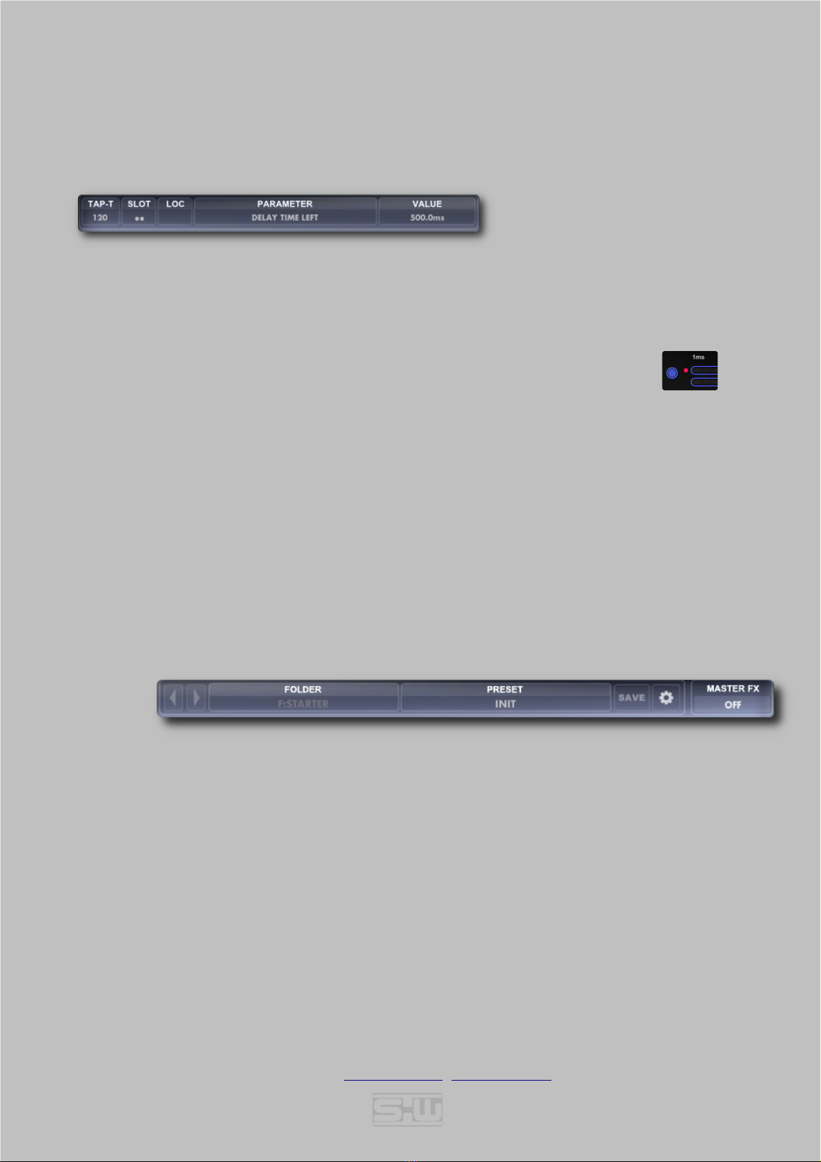
TOP DISPLAY
PARAMETER DISPLAY
TAP-T: The TAP-T[IME] area combines three functions:
1. If a non synced delay time is set with the delay time slider, the correspondin bpm is
displayed here.
2. Ri ht click into the area for tap-time tar et selection. [Slot 1-4 left/ri ht]. If a tar et
is selected the delay switches to non synced ( s based) time mode and is in stand
by for 5 seconds after the receivin the last tap tempo click. This is indicated by a
blinkin red dot in front of the delay channel.
3. Left click into the area after selectin a tap-tempo tar et sends tempo information to the delay
channel.
SLOT: The correspondin slot of the selected parameter.
LOC: “Hook-point” of the effect if a effect parameter is selected. Pre-Delay [PRE], Delay, Feedback [FB],
Post-Delay [POST]
PARAMETER: The name of the last chan ed parameter.
Note: This display shows „DEMO MODE“ until REFLEX-PRO-X is registered with a valid license key.
VALUE: The value of the last used parameter.
Note: This display shows „REGISTER“ until REFLEX-PRO-X is registered with a valid license key.
You can enter the registration display by clicking on 'REGISTER'. (See registering description)
PRESET DISPLAY
ARROW LEFT: Steps throu h presets downwards in alphabetical order.
ARROW RIGHT: Steps throu h presets upwards in alphabetical order.
FOLDER: Folder of actual preset. Ri ht click on the folder area opens the REFLEX-PRO-X preset directory.
PRESET: Selected Preset. Click on Preset Name opens a Drop down menu for direct preset selection.
SAVE: Saves the actual parameter settin s to a new preset file. The default location for User presets is the
“User Preset” folder which will open after hittin save. You can also add subfolders [like in the
“Factory Preset” folder] to or anize your presets. All other locations could be used to save a preset but
will be i nored in the preset listin and you'll et the warnin : “NOT SAVED IN USER FOLDER!”
OPTIONS: Opens the 'Options' pa e.
© 2020-2021 Stefan Weyel www.stw-audio.com [email protected] doc version 1.2.0
8
_______________________________
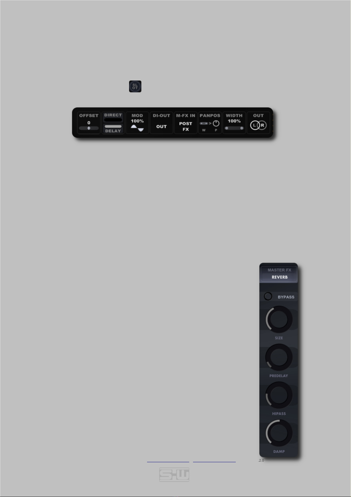
SLOT SETTINGS
The slot settin s pa e contains some additional slot parameters which affect si nal routin and controls. The slot pa e
can be entered or left with a click on the icon
OFFSET: Fix Offset Delay of one side of the input channels. [0 - 25ms]
DIRECT/DELAY: Mix of direct and delay si nal routed to the POST FX section.
[100% DIRECT – 100% DELAY]
MODULATION: Modulation depth [see BOTTOM SETTINGS] of the main Delay Line. [0% - 100%]
DI-OUT: Source of slots Direct Out send. [PRE FX, DELAY, POST FX, OUT]
M-FX IN: Source of slots Master Effect send. [INPUT, PRE FX, DELAY, POST FX, OUT]
PANPOS: Position of the Pan Pot. [Post or Pre Width].
WIDTH: Stereo width of slots output. [0% - 100%]
OUT: Swaps or mutes the left and ri ht outputs [L-R, R–L, X-X]. Mutin the output can be a simple
way of 100% wet routin throu h the MasterFX section , e. . EQs
_______________________________
MASTER EFFECT
EFFECT SELECTOR: Drop down Menu for the master effect selection.
Available Effects are:
•REFLEX: A delay based ambience effect also known from the
REFLEX+ plu in.
•REVERB: A dense reverb al orithm with decent modulations
•ROOM: A room ambience with rou her density.
•FIX EQ: 3 band EQ with fixed Lo/Hi h band and tunable mid band.
•2 BAND EQ: Two band EQ with FREQ and GAIN parameters.
•LO/HI SHELF: Shelvin filter
•DRIVE LP+HP: Lo-pass and Hi-pass with ain.
BYPASS: Dry si nal is routed to the MASTER FX output if Bypass is active.
PARAMETER 1 - 4: Each master effect holds up to 4 individual parameters. The actual
knob assi nment is displayed below the knobs. Available values
depend on the actual knob parameter.
© 2020-2021 Stefan Weyel www.stw-audio.com [email protected] doc version 1.2.0

9
REFLEX:
SIZE: Delay time of the REFLEX al orithm [0% - 100%]
DECAY: Decay time of the REFLEX al orithm [0% - 100%]
MODULATION: Modulation depth of the REFLEX al orithm [0% - 100%]
DAMP: Feedback Dampin frequency [20kHz - 50Hz]
REVERB:
SIZE: Decay time of the REVERB al orithm [1s - 30s]
PREDELAY: Pre-delay time until reverb tail ets in [0ms - 500ms]
HIPASS: Cutoff frequency of the Hi-pass filter. [50Hz - 2000Hz]
DAMP: Hi frequency dampin amount. [0% - 100%]
ROOM:
SIZE: Decay time of the ROOM al orithm [1s - 4s]
PREDELAY: Pre-delay time until reverb tail ets in [0ms - 500ms]
HIPASS: Cutoff frequency of the Hi-pass filter. [50Hz - 2000Hz]
DAMP: Hi frequency dampin amount. [0% - 100%]
FIX EQ: [LO SHELF + VARIABLE MID BAND + HI SHELF]
LOSHELF: Gain of the Lo band [shelvin type] at 500Hz [-18dB - +18dB]
MID FREQ: Center Frequency of the mid band. [500Hz - 5000Hz]
MODULATION: Gain of the Mid band [-18dB - +18dB]
HISHELF: Gain of the Hi band [shelvin type] at 3000Hz [-18dB - +18dB]
2 BAND EQ: [TWO BAND PEAK FILTER]
LO GAIN: Gain of the 1s band [-18dB - +18dB]
LO FREQ: Frequency of the 1st band [50Hz - 20kHz]
HI GAIN: Gain of the 2nd band [-18dB - +18dB]
HI FREQ: Frequency of the 2nd band [50Hz - 20kHz]
LO/HI SHELF : [VARIABLE LO SHELF + HI SHELF]
LO GAIN: Gain of the 1s band [-18dB - +18dB]
LO FREQ: Frequency of the 1st band [50Hz - 1000Hz]
HI GAIN: Gain of the 2nd band [-18dB - +18dB]
HI FEEQ: Frequency of the 2nd band [250Hz – 7500kHz]
DRIVE LP+HP: : [LOPASS + HIPASS]
HI PASS: Frequency of the Hi-pass filter [50Hz -20000Hz]
LO PASS: Frequency of the Lo-pass filter [50Hz -20000Hz]
GAIN: Gain amount [0% - 100%]
MODE: Slope [12dB, 24dB, 36dB] and routin of the filters [Parallel/Serial]
© 2020-2021 Stefan Weyel www.stw-audio.com [email protected] doc version 1.2.0

10
_______________________________
MASTER SETTINGS
WEB: Clickin the „STW au io“ lo o launches a link to the stw-audio homepa e.
KILL: All audio buffers are cleared. Use this in emer ency cases, or to abort lon delay feedbacks.
MODULATION RATE: Modulation Rate of slots main delay modulation. [0% - 100%]
MODULATION DEPTH: Maximum overall Modulation depth of slots main delay modulation. The relative ratio to that
maximum depth can be set individually for each slot at the slot settin pa e. [0% - 100%]
FEEDBACK OFFSET: Overall offset of slots feedback settin . Use this to decrease or increase the feedback amount
for all slots at once. [-50% - +50%]
DELAY TIME SCALE: Scale factor for all delay times [x0.5 – x2.0]
LIMITER MODE: Enable/Disable the master limiter. The final limiter takes the sum of all four slots as input and
sends it to the 'WET' control. Modes are['Off', 'Slow 1' (Ori inal Mode), 'Slow 2', 'Fast']
BOOST: Input Gain of the master limiter. [0 - 36dB]
SEND: Mutes the dry amount of the audio output. This should be the preferred mode if REFLEX-
PRO-X is used as send effect.
ATTENUATION: Additional attenuation of all input ains. [0dB, -3dB, -6dB, -12dB]
To keep wet/dry balance this also affects the dry output level.
NOTE: “SEND” ode and INPUT ATTENUATION are not part of the preset data but rather saved as a plugin state in
your projects.
DRY LEVEL: Amount of dry input si nal added to the plu s audio output. [0% - 100%]
WET LEVEL: Amount of wet effect si nal added to the plu s audio output. [0% - 100%]
WIDTH: Stereo amount of wet si nal. Value < 100% = decreased stereo si nal,
value > 100% = decreased mono si nal. [0% - 150%]
OUTPUT GAIN: Attenuation or ain of the plu s output si nal. [-12dB - +12dB]
© 2020-2021 Stefan Weyel www.stw-audio.com [email protected] doc version 1.2.0

11
OUTPUT VU: VU meter for each Slot, Master Effect and Left/Ri ht main output.
MASTER FX LEVEL: Amount of the MASTER EFFECT output. [0% - 200%]
_______________________________
FEED ACK MATRIX
The feedback matrix allows to route each slots main delay feedback path into each other slots main delay.
FEEDBACK AMOUNT: Positive or ne ative [phase inverted] amount of slots 1 – 4 feedback amount into the
correspondin slot. These settin s are all relative to the Main Feedback level in the MAIN
SECTION of the appropriate slot. [-100% - +100%]
_______________________________
DELAY MODES
The delay section provides a stereo delay module with four different delay modes for every slot. All comin with
individual parameters. The max delay time for each delay line is 8 seconds. Synced and free time modes displays are
similar in FORWARD, BACKWARD, and GRAIN mode. The TAP DELAY MODE offers a wide variety of individual
settin s for each delay tap (see TAP EDIT PAGE).
FORWARD MODE (synced ti e ode)
© 2020-2021 Stefan Weyel www.stw-audio.com [email protected] doc version 1.2.0

12
FORWARD MODE (free ti e ode)
ON: Enables/Disables the delay module.
TAP/TIME
SELECT: ['TAP' Dots - In synced mode] Sets the Delay time to the selected note len th multiplied with the upper
circle number. Left and ri ht channel can have individual settin s.
['TIME' Slider - In free mode] Sets left and ri ht Delay time with the horizontal faders.
TIMEBASE: Delay time base. [Note len th of 1/16th, 1/32nd, 1/64th, 1/8th triplet, 1/16th triplet, 1/32nd triplet.
Option “Milliseconds” , chan es to non synced display]. (All four delay odes)
MODE: Main Delay mode. FORWARD / BACKWARD / GRAIN / TAP
LINK: Links left and ri ht channel time settin s. (Forward/Backward and Grain ode).
ROUTING: Selects the feedback and output routin of the delay (forward and backward mode).
•DUAL MONO: Left and ri ht input o to own input, feedback and output.
•LEFT PING PONG: Left input oes into left input and is feed back into the ri ht channel. Ri ht
feedback oes into the left channel afterwards.
•MONO LEFT PING PONG: Same as LEFT PING PONG, just with the mono input si nal.
•RIGHT PING PONG: Ri ht input oes into ri ht input and is feed back into the left channel.
Left feedback oes into the ri ht channel afterwards.
•MONO RIGTH PING PONG: Same as RIGHT PING PONG, just with the mono input si nal.
•LEFT/RIGHT PING PONG: Left and ri ht channel o into own input and feed back to each
other.
•MIX: Left and ri ht channel o into own input and feedback to both channels.
•MONO LEFT: Only left channel is processed and routed to both outputs.
•MONO RIGHT: Only ri ht channel is processed and routed to both outputs.
FEEDBACK
MODE: Proportional/Linear feedback mode.
In proportional mode left and ri ht channels have the same release time when different delay
times are set. (Only active in DUAL MONO ode).
SPREAD: Spreads left and ri ht delay times in milliseconds. Opposite to the offset delay time the spread time
sums up every feedback loop. [-20ms - +20ms]
HIPASS: Cutoff frequency of the delay output Hi-pass filter [20Hz - 3000Hz]
LOPASS: Cutoff frequency of the delay output Lo-pass filter [200Hz - 20000Hz]
© 2020-2021 Stefan Weyel www.stw-audio.com [email protected] doc version 1.2.0

13
BACKWARD MODE (synced ti e shown)
TRIGGER: Tri er source to start delay read fro the top. Useful for timed reverse delays.
•OFF - Reverse buffer reads are runnin free.
•BAR – Delay buffer writes start at every new bar from top.
•ENV1/2 – Delay buffer writes start at every envelope tri er [Envelope follower is in
GATE mode and the envelope level exceeds the threshold level].
Note: Reverse buffer reads are delayed for the selected delay ti e. That eans the buffer has to be filled with the delay
length first before the read starts. In case of e.g. a delay length of 1/16th the reverse buffer read starts 1/16th after the
written input sa ple and is read fro the buffer head in reverse. The first input sa ple is therefore reached after 2/16th.
So the attack of a percussive sound will be heard at the doubled a ount of the selected delay ti e.
POSITION: Delay buffer read position
X-FADE: Crossfade time from top/end of buffer frames. [10ms - 1000ms]
LOPASS: Cutoff frequency of the delay output Lo-pass filter [200Hz - 20000Hz]
GRAIN MODE (synced ti e shown)
SMOOTH: Smoothin of rains. AUTO sets a pre-calculated time which fits to the linked parameters.
[AUTO, 0ms – 50ms ]
POSITION: Read position relative to the delay time buffer start. 0% is head, 100% is tail of the buffer. [0% - 100%]
SPEED: Playback speed of delay buffer. -100% results in one octave lower, +100% in one octave hi her pitch.
[-100% - +100%]
SIZE: Size of rains. [5ms – 400ms]
© 2020-2021 Stefan Weyel www.stw-audio.com [email protected] doc version 1.2.0

14
TAPPED MODE
LENGTH: Click on a top row numbers sets the amount of delay taps. Inactive delay taps are reyed out.
ENABLE: Click on a tap circle enables/disables the delay tap. White taps are enabled.
DIRECT OUT POSITION: Direct out feed of the delay line could be the last tap or the sum of all taps
output.
FEEDBACK POSITION: Available taps are 1-16 or auto select of last tap in selected len th. Feedback
position can exceed the actual tap amount and is independent of tap enabled settin and tap
len th..
MODE: Tap delay process modes are:
•STEREO: Independent left/ri ht delay tap outs.
•DUAL MONO: Left/ri ht delay taps are summed to a mono out.
•LEFT MONO: Only left delay taps are routed to a mono out.
•RIGHT MONO: Only ri ht delay taps are routed to a mono out.
TAP EDIT: Opens the Tap Edit Pa e.
Closes the Tap Edit Pa e
EDIT PAGE: To les TIME/LEVEL/PAN and FX Tap Edit Pa e.
(Only visible if Tap Edit Page is opened)
SWELL: Adds additional pre delays to every tap [0% - 100%]. This creates some smoothin effect.
(Only visible if Tap Edit Page is closed)
SET: Drop down menu to select from predefined tap settin s.
SWING: Swin amount of consecutive taps. If a binary timebase is used (e. . 1/8th) an amount of 100%
extends all odd taps to a two 1/8th triplets and shortens all even taps to one 1/8th triplet. [0% – 100%].
TAP TIME: Manual tap delay time [1ms – 500ms/Tap]. (Could also be set by Tap-Te po)
The tap time knob follows the synced timebase values
© 2020-2021 Stefan Weyel www.stw-audio.com [email protected] doc version 1.2.0
15
_______________________________
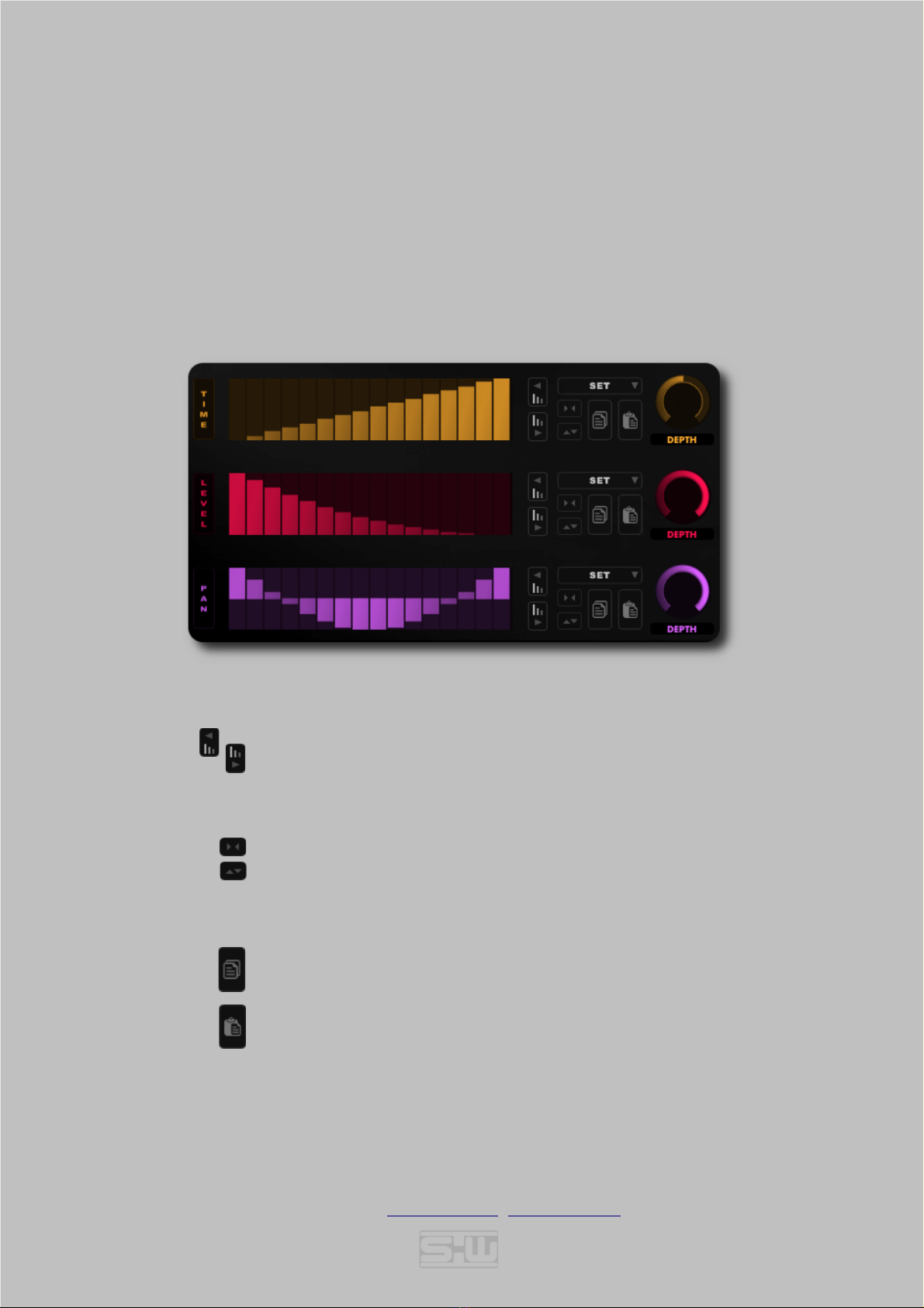
TAP EDIT PAGE
The Tap Edit Pa es allows individual settin s for every sin le delay tap. All step edits share the same functionality:
Drawin of sin le or multiple levels on the fly for tap time/level and panorama. Panorama sliders cover a ran e from
-100% to 100%, and the effect depends on the selected Tap Mode.
Time and level sliders cover a ran e from 0% - 100%. 100% time level corresponds to the selected time value at the Tap
Delay Pa e!
Ri ht click into a fader area opens a step menu. A selected step amount enables a step rid for fixed slider divisions.
TAP EDIT PAGE 1
NUDGE LEFT: Moves all sliders one step left.
NUDGE RIGHT: Moves all sliders one step ri ht.
SET: Drop down menu to select from predefined slider settin s.
REVERSE LEVELS: Reverse slider values. First becomes last and the other way round.
INVERSE LEVELS: Inverse slider values. 0% becomes 100% and the other way round.
Note: SET/REVERSE/INVERSE are applied on the selected tap length only.
COPY LEVELS: Slider values are copied to the clipboard buffer.
PASTE LEVELS: Slider values are pasted from the clipboard buffer.
DEPTH: Overall depth of the slider values.
© 2020-2021 Stefan Weyel www.stw-audio.com [email protected] doc version 1.2.0

16
TAP EDIT (FX) PAGE 2
Tap Edit Pa e 2 can control up to two individual post delay FX parameters.
If a parameter is set in the PARAM1/2 menu the actual POST FX becomes a POST 'TAP' FX
which provides individual values for each tap of the selected POST FX parameter. Since each tap uses its own FX
instance this can become CPU expensive if used extensively.
Modulation (if a odulation source is set at the FX Page), as well as
FX activation can be enabled or disabled for each tap individually.
Note: Right click into a Mod[M] or Active[ON] button row toggles all boxes enabled or disabled.
All other control elements on this pa e share the same functionality as on TAP EDIT PAGE 1.
© 2020-2021 Stefan Weyel www.stw-audio.com [email protected] doc version 1.2.0

17
_______________________________
DSP EFFECTS
The DSP effect section is divided into a PRE-Delay, a FEEDBACK and a POST-Delay section. A
detailed effect description can be found in the followin section parts. A click on the effect icon
opens the effect selection pa e. Hoverin over the display moves a rectan le which visualizes the
selected effect when clickin . Clickin on an empty rectan le closes the effect selector and leaves
your settin s unchan ed.
_______________________________
PRE/POST EFFECTS
A collection of 15 different effects could be invoked in the pre or post delay audio path. Pre/Post effects share the same
effects pool. All effects share the enable/disable button. Most effects also share the “MIX” parameter which sets the ratio
of dry/wet si nal in the ran e from 0% - 100%. These are not further explained in the individual effect descriptions.
© 2020-2021 Stefan Weyel www.stw-audio.com [email protected] doc version 1.2.0

18
FREQUENCY SHIFTER
FREQUENCY: Frequency shift f the input si nal. [-1Hz - +1Hz]
SCALE: Scalin factor of the shift frequency. Scalin factors are [x10, x100, x1000]
FEEDBACK: Output feedback amount to freq shifter input. [0% - 100%]
SPREAD: Frequency spread factor of left/ri ht channel. [-100% - 100%]
RING MODULATOR
FREQUENCY: Frequency of the modulator si nal. [0Hz - 2000Hz]
SHAPE: Shape of the modulatin wave. Greater values produce more overtones. [0% - 100%]
WIDTH: Amount of si nal phase to panorama. [0% - 100%]
SPREAD: Frequency spread factor of left/ri ht channel. [-100% - 100%]
PHASER
BASE: Phaser Base frequency. [100Hz – 5kHz]
DEPTH: Depth of phasin notches. [0% - 100%]
STAGES: Amount of phaser sta es. [2 - 8]
SPREAD: Base frequency spread factor of left/ri ht channel. [-25% - +25%]
FEEDBACK: Output feedback amount to phaser input. [0% - 100%]
© 2020-2021 Stefan Weyel www.stw-audio.com [email protected] doc version 1.2.0

19
PITCH SHIFTER I
COARSE: Coarse pitch shift value. [-12 - +12 semitones]
FINE: Fine pitch shift value. [-100 - +100 cent.]
DELAY: Pitch shifter buffer size. Low values fit best for percussive si nals hi her values fit best for sustainin
sounds. [1ms - 100ms]
SPREAD: Pitch shift spread factor of left/ri ht channel. [-100% - 100%]
PITCH SHIFTER II
COARSE L: Coarse pitch shift value of left channel. [-12 - +12 semitones]
COARSE R: Coarse pitch shift value of ri ht channel. [-12 - +12 semitones]
WIDTH: Pannin width of left and ri ht channel. -100% results in ri ht channel on left output, left channel on
ri ht output. 0% results to mono si nal of both channels, 100% results in ri ht channel on ri ht output,
left channel on left output. [-100% - +100%]
DETUNE: Adds a ne ative detune value to the left channel and positive detune value to the ri ht channel.
[10% - 100]
SATURATION/RECTIFY/DESTROY/NOISE
GAIN: Gain factor on input si nal. [0% - 100%]
LOPASS: Cutoff frequency of the post ain sta e Lo-pass filter. [50Hz - 20kHz]
Q: Q (Resonance) amount. [0% - 100%]
SPREAD: Cutoff frequency spread factor of left/ri ht channel. [-100% - +100%]
© 2020-2021 Stefan Weyel www.stw-audio.com [email protected] doc version 1.2.0

20
LOFI I - Downsa pling with Hi-pass Filter
RATE: Amount of sample rate reduction. [0% - 100%]
HIPASS: Cutoff frequency of the post ain sta e Hi-pass filter. [50Hz - 20kHz]
Q: Q (Resonance) amount. [0% - 100%]
SPREAD: Cutoff frequency spread factor of left/ri ht channel. [-100% - +100%]
LOFI II - Lofi algorith collection
DRIVE: Gain amount. [0% - 100%]
NOISE: Noise amount. [0% - 100%]
DNSAMPLE: Downsamplin amount. [0% - 100%]
BITCRUSH: Bitcrush amount. [0% - 100%]
WAVE SHAPE with Bandpass Filter
MODE: Wave Shape Mode. [0% - 100%]
GAIN: Noise amount. [0dB - 24dB]
FREQ: Frequency of the pre ain sta e Bandpass filter. [50Hz - 20kHz]
Q: Q (Resonance) amount. [0% - 100%]
© 2020-2021 Stefan Weyel www.stw-audio.com [email protected] doc version 1.2.0
Table of contents


