Sub-Zero WOLF BW Series User manual

Page 2
1-2
#7040743 - Revision A - September, 2016
General Information Built-In Wine Storage (BW) Series
Built-In Wine Storage (BW) Series
TECHNICAL ASSISTANCE
If you should have any questions regarding the WS
Series and/or this manual, please contact:
Sub-Zero, Inc.
ATTN: Service Department
P.O. Box 44988
Madison, WI 53744 - 4988
Customer Assistance
Phone #: (800) 222 - 7820
Facsimile #: (608) 441 - 5887
Technical Assistance
(For Technicians in Customer’s Homes Only)
Phone #: (800) 919 - 8324
Warranty Claims
Phone #: (800) 222 - 7820
Facsimile #: (608) 441 - 5886
Service Department e-mail Address:
Office Hours:
7:00 AM to 7:00 PM Central Time
Monday through Friday
IMPORTANT SAFETY INFORMATION
Below are Product Safety Labels used in this manual.
The "Signal Words" used are WARNING or CAUTION.
When reviewing this manual, please note these differ-
ent Product Safety Labels placed at the beginning of
certain sections of this manual. You must follow the
instructions given in the boxes of the Product Safety
Labels in order to avoid personal injury and/or product
damage.
The sample Product Safety Labels below illustrate the
precautions that should be taken when the signal word
is observed.
INTRODUCTION
This Technical Service Manual has been compiled to provide the most recent service information for Built-In Wine
Storage Series appliances. The information in this manual will enable the service technician to diagnose malfunc-
tions, perform necessary repairs, and return a BW Series unit to proper operational condition.
The service technician should read the complete instructions contained in this manual before initiating any repairs.
INDICATES THAT HAZARDOUS OR UNSAFE
PRACTICES COULD RESULT IN SEVERE PERSON-
AL INJURY OR DEATH!
Indicates that hazardous or unsafe practices could
result in minor personal injury, and/or product
damage, and/or property damage!
In addition, please pay attention to the signal word
“NOTE”, which highlights information that is especially
important for the topic being covered.
This manual is designed to be used by Certified Service Personnel only. Sub-Zero Group, Inc. assumes no
responsibility for any repairs made on Sub-Zero refrigeration units by anyone other than Certified Service
Technicians.
The information and images contained in this manual are the copyright property of Sub-Zero Group, Inc. Neither
this manual nor any information or images contained herein may be copied or used in whole or in part without the
express written consent of Sub-Zero Group, Inc.©, all rights reserved.

Page 3
1-3 #7040743 - Revision A - September, 2016
General Information
Built-In Wine Storage (BW) Series
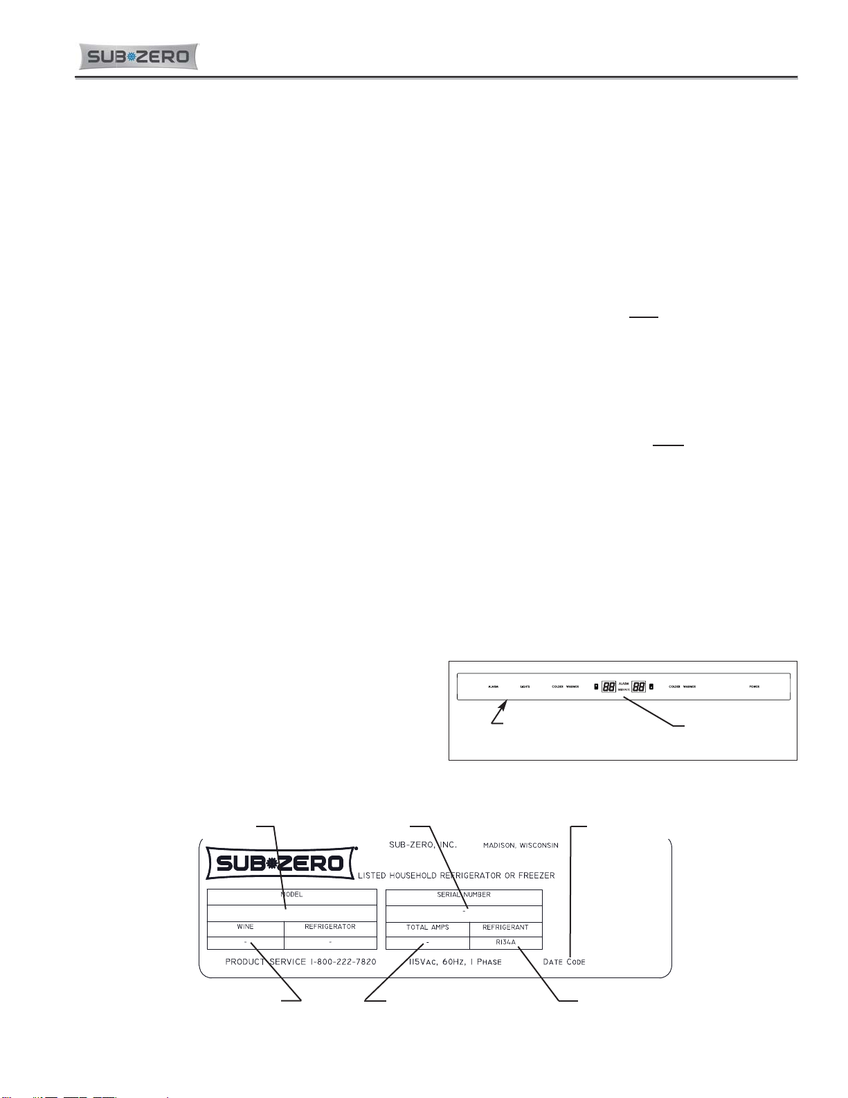
Serial Tag Location Control Panel
Figure 1-1. Serial Tag Location
WARRANTY INFORMATION
This page summarizes the 2, 5 & 12 Year Warranty pro-
vided with every Sub-Zero appliance, as well as the two
special warranties:
•Non-Residential Warranty - Applies to units installed
in non-residential applications.
•Display/Model Home Warranty - Applies to distribu-
tor and dealer display units, and units in model
homes, sold three years after date of manufacture.
Following the warranty summaries are details and notes
about the warranties.
TWO, FIVE & TWELVE YEAR Warranty
• 2 year TOTAL PRODUCT, *parts and labor.
• 5 Year SEALED SYSTEM, **parts and labor.
• 6th - 12th year LIMITED SEALED SYSTEM, **parts
only.
ONE & FIVE YEAR Non-Residential Warranty
(Example: Office, Yacht, etc.)
• 1 Year TOTAL PRODUCT, *parts and labor.
• 5 Year SEALED SYSTEM, **parts and labor.
ONE & FIVE YEAR Display/Model Home Warranty
(Display units sold three years after date of manu-
facture)
• 1 Year TOTAL PRODUCT, *parts and labor.
• 5 Year SEALED SYSTEM, **parts and labor.
Figure 1-2. Serial Tag Layout (Layout Reference Only)
Warranty Details:
* Includes, but is not limited to the following:
Electronic Control System Components, Fan & Light
Switches, Fan Motors & Blades, Drain Pan, Drain
Tubes, Wiring, Light sockets & bulbs, Door Hinge
Assemblies, Door closers, Compressor Electricals,
etc. . .
** Includes the following:
Compressors, Condenser, Evaporators, Filter-Driers,
Heat-exchangers, All Tubing that Carries the Freon.
NOTE: Condenser Fan Motors, Freon, Solder and
compressor electricals are NOT considered sealed
system parts.
Warranty Notes:
Stainless Steel doors, panels, grilles & product•
frames are covered by a 60 day parts & labor war-
ranty for cosmetic defects.
All warranties begin at unit's initial installation date.•
•
All Warranty and Service information collected by•
Sub-Zero is arranged and stored under the unit
serial number, and the customer's last name.
Sub-Zero requests that you have the model and•
serial numbers available whenever contacting the
factory or parts distributor.
•
The serial number tag for models BW-30 is located•
on the bottom side of the compartment divider,
directly behind the control panel. (See Figures 1-1
and 1-2)
BW-30/S/PH-LH
Model Number Serial Number Manufacture Date
Refrigerant Charge Total Amps Refrigerant Type

Page 4
1-4
#7040743 - Revision A - September, 2016
General Information Built-In Wine Storage (BW) Series
Built-In Wine Storage (BW) Series
Home security
tie-in
Discreet lighting
Lighted electronic
control panel
Display shelf
Roller-assembly
shelves
Hermetically sealed
refrigeration system
Full-view glass
door
UV-resistant glass
Divider gasket
Location of rating
plate
Removable
kickplate
MODEL # MODEL DESCRIPTION
BW-30/O Built-In Wine Storage - 30” Wide/Overlay Panel Application Door
BW-30A/O Built-In Wine Storage - 30” Wide with High Altitude Glass/Overlay Panel Application Door
BW-30/S/TH Built-In Wine Storage - 30” Wide/Classic Stainless Steel Door/Tubular Handle
BW-30/S/PH Built-In Wine Storage - 30” Wide/Classic Stainless Steel Door/Pro Handle
BW-30A/S/TH Built-In Wine Storage - 30” Wide with High Altitude Glass/Stainless Steel Door/Tubular Handle
BW-30A/S/PH Built-In Wine Storage - 30” Wide with High Altitude Glass/Stainless Steel Door/Pro Handle
NOTE: A “-RH” or “-LH” at the end of the model number indicates Right-Hand or Left-Hand swing, respectively.
MODEL DESCRIPTIONS
This section briefly describes the models covered in this Technical Service Manual.
NOTE: Functional parts are common to each model configuration, meaning for example, models BW-30/O, BW-
30/S/TH, and etc., will utilize common functional parts. For this reason, only the basic model number (Model BW-
30) is used in this manual, unless otherwise specified.

Page 5
2-2
#7040743 - Revision A - September, 2016
Electronic Control System Built-In Wine Storage (BW) Series
Built-In Wine Storage (BW) Series
Term/Component Definition / Description
Main Control Board ……....….. The printed-circuit board (PC Board) which contains a microprocessor, relays, and
electrical connections that monitor and control all functions of the appliance.
Microprocessor ………......…... An electrical component on the control board which receives electrical signals from
other components, processes the information, then sends electrical signals to relays
on the board to open or close, switching components in the appliance ON or OFF.
Relay …………………….……. An electrical component on the control board which switches other components in
the appliance ON or OFF when instructed to do so by the microprocessor.
Control Panel Assembly …….. That part of the electronic control system where manual commands are entered via
key-strokes and information is displayed; located between the two wine storage
zones.
Membrane Switch ………..….. An integral part of the control panel assembly consisting of the function keys used
for all input commands to the electronic control system.
Keys (Function Keys) ………… The keys or buttons on the membrane switch. (The keys are: UNIT ON/OFF,
LIGHTS ON/OFF, ALARM ON/OFF, COLDER, WARMER)
LED (Light-Emitting Diode) ….. A semiconductor diode that emits light when power is supplied to it. In the control
panel assembly, LED’s are arranged to show values and codes. They are also used
as back-lighting for icons and indicators in the control panel.
Icons / Indicators ……........…... The words, numbers and symbols visible at and on the control panel assembly.
(Example: Temperatures, alarm bell, “SERVICE”, error/fault codes, etc.)
Set-Point ……………………..... The desired zone temperature, established by pressing the COLDER and/or
WARMER keys.
High Offset (Cut-in)…..……..... During normal operation of a wine storage unit, it is the maximum evaporator tem-
perature the electronic control system will allow before calling for cooling.
Low Offset (Cut-out)……...…... During normal operation of a wine storage unit, it is the minimum compartment air
temperature the electronic control system will allow before interrupting cooling.
Offset Temperature Range …... The difference between the low offset and the high offset.
Thermistor ..........................….. (a.k.a. Temperature Sensor) A resistor with which resistance changes as tempera-
ture around it changes. For electronic control system purposes, the microprocessor
detects, monitors and processes this resistance value in order to control cooling
functions as well as displays it as a temperature reading at the control panel.
Display Units of Measure…….. Temperatures displayed at the control panel may be in fahrenheit (°F), or celsius
(°C), units of measure. Switching from one to the other display units of measure is
accomplished through a series of key strokes.
Error (Fault) Codes .………..... The codes that appear at the control panel display windows if the unit experienced
specific problems related to electrical signals supplied to the microprocessor.
Electrical “Pulse”....................... A non-constant supply of voltage, or electrical signal, the duration of which is often
measured in milliseconds.
Electrical Polarity....................... The positive ( + ) and negative ( - ) sides of the alternating current sinewave.
ELECTRONIC CONTROL TERMINOLOGY & COMPONENT DESCRIPTIONS
The BW Series utilizes an electronic control system which monitors, regulates, controls and displays a variety of
functions and operations in the appliance.
The table below defines some of the basic electronic control system terminology.

Page 6
2-3 #7040743 - Revision A - September, 2016
Electronic Control System
Built-In Wine Storage (BW) Series
BASIC WINE STORAGE ELECTRONIC CONTROL SYSTEM
This page contains a basic illustration of the BW Series electronic control system (See Figure 2-1). Input operations
are performed at the membrane switch (part of the the control panel assembly), with monitoring, regulating and con-
trolling functions taking place at the control board (located directly behind the control panel). Temperatures and pos-
sible problems with the unit are displayed at the control panel display. The entire electronic control system is
described in greater detail on the following pages.
NOTE: The diagram below is not an exact electrical representation of the electronic control system. For more
detailed electrical diagrams refer to the wiring diagram and schematic supplied with the unit.
Figure 2-1. Basic BW Series Electronic Control System
N.C.

Page 7
2-4
#7040743 - Revision A - September, 2016
Electronic Control System Built-In Wine Storage (BW) Series
Built-In Wine Storage (BW) Series
E3
E2
E1
14 21
J3
81
J2
J1
J8
WINE
CONTROL
BOARD
P3
Figure 2-2. Control Board Layout
Figure 2-3. Control Board Summary Table
CIRCUIT
E1
E2
E3
P14
J3
P12
P13
P11
P8
P10
P9
P6
P7
DOOR SWITCH
120 VOLT CIRCUITS
COMPRESSOR
DESCRIPTION
POWER IN
EMPTY
GROUND
NEUTRAL
EMPTY
EMPTY
LIGHTS
LOWER EVAP FAN
UPPER EVAP FAN
EMPTY
BUILT-IN WINE STORAGE SERIES CONTROL BOARD SUMMARY/ LAYOUT
DOOR SWITCH INPUT
POWERS COMPRESSOR
POWER INTO BOARD
FUNCTION
COOLS UPPER COMPARTMENT
COOLS LOWER COMPARTMENT
ON WHEN LIGHTS ON 100%
NEUTRAL INTO BOARD
EARTH GROUND
BROWN
BLACK
GRAY
COLOR
GREEN
WHITE
BLUE
ORANGE
PINK
EMPTY
ALARM CIRCUIT-NORMALLY CLOSED
LOW VOLTAGE CIRCUITS
ALARM CIRCUIT
ALARM CIRCUIT-OPEN
UPPER CABINET
LOWER CABINET
LOWER CABINET
THERMISTOR CIRCUITS
UPPER CABINET
LOWER EVAPORATOR
LOWER EVAPORATOR
UPPER EVAPORATOR
UPPER EVAPORATOR
ALARM CIRCUIT-NORMALLY OPEN
REFRIGERANT VALVE
CIRCUIT
P3
P4
P5
J3
J2
P1
P2
P3
P4
P5
P6
P8
P7
FOR HOME ALARMS WHT/BLUE
FOR HOME ALARMS
DESCRIPTION FUNCTION COLOR
WHT/RED
FOR HOME ALARMS
SENSES TEMPERATURE
GRAY/WHT
BLUE/WHITE
BLUE/WHITE
BLUE/BLACK
BLUE/BLACK
BLUE/RED
ORANGE/RED
ORANGE/YELL
BLUE/YELLOW
SENSES TEMPERATURE
SENSES TEMPERATURE
SENSES TEMPERATURE
SENSES TEMPERATURE
SENSES TEMPERATURE
SENSES TEMPERATURE
SENSES TEMPERATURE
P1
P2
CONTROL REF TAN
WINE STORAGE CONTROL BOARD
LAYOUT AND SUMMARY TABLE
The electrical connection points on the wine storage control board
are labeled Alphanumerically. These labels correspond with the
alphanumeric control board summary layout table on the wiring dia-
gram. By referencing the table, it is possible to identify which com-
ponents are connected at which connection points on the control
board. Below is a layout diagram of the control board, followed by
a copy of a summary table. (See Figures 2-2 and 2-3)
NOTE: All components on the control board are non-replaceable.
If problems with the control board are identified, the complete con-
trol board must be replaced.

Page 8
2-5 #7040743 - Revision A - September, 2016
Electronic Control System
Built-In Wine Storage (BW) Series
WINE STORAGE CONTROL PANEL LAYOUT
Figure 2-4. Wine Storage Control Panel Layout
Figure 2-5. Switching Unit ON or OFF, Press POWER Key
BASIC INPUT OPERATIONS
The following pages describe the basic input operations performed at the control panel (switching unit ON and OFF,
adjusting temperature set-point, switching lighting system ON and OFF, and enabling and disabling the tempera-
ture/door alarm feature).
POWER
All units are shipped in the OFF Mode. When electricity is supplied to the appliance, a short power up is initiated
where the temperature units of measure (°F or °C) is displayed for one second, followed by the model code for five
seconds, then all components are switched OFF and the LED displays go blank. By pressing the POWER key, elec-
tricity is allowed past the control board to the rest of the unit, indicated by the lights energizing, the cooling functions
beginning and temperatures appearing in the LED display windows. (See Figure 2-5).
TEMP/DOOR
Alarm
&
SERVICE
indicators
Upper
Compartment LED
Display Window
Upper Compartment
COLDER
key
WARMER
key
Lower Compartment
COLDER
key
WARMER
key
POWER
key
LIGHTS
ON/OFF
key
SHOCK HAZARD! WHEN IN OFF MODE, AC LINE VOLTAGE IS STILL PRESENT AT CONTROL BOARD!
Lower
Compartment LED
Display Window
ALARM
ON/OFF key

Page 9
2-6
#7040743 - Revision A - September, 2016
Electronic Control System Built-In Wine Storage (BW) Series
Built-In Wine Storage (BW) Series
Adjusting Set-Points
To adjust set-points, press the WARMER or COLDER keys on the control panel in multiple key strokes until the
desired set-point is achieved (See Figure 2-6). One key stroke equals a one degree change. The set-point will be
displayed for three seconds after the last key stroke. After three seconds, the compartment temperature will be dis-
played. As the compartment temperature changes, the temperature displayed will change by no more than one
degree per minute.
NOTECor: The temperature range in a wine storage compartment is 40°F to 65°F.
Figure 2-6. Adjust Set-Point - Press COLDER or WARMER Keys in Multiple Key Strokes
Lighting System ON/OFF
For the purpose of displaying a wine supply, it is possible to energize the lights 100% of the time, even when the
door is closed. To do so, press and release the LIGHTS key (See Figures 2-7). To switch back to normal lighting
operation, press and release the LIGHTS key again.
Temperature Alarm and Door Alarm ON/OFF
There is an audio/visual temperature and door alarm in the BW-30 unit that can be enabled to warn a customer of
temperatures problems or if the door was left open. To enable the alarm, press and release the ALARM key (See
Figure 2-8). If the alarm is enabled, then the alarm icon on the display is illuminated. To disable this feature, press
and release the ALARM key again, and the alarm icon is de-energized.
NOTE: If the alarm is enabled and temperature problems or door ajar are experienced, the alarm icon flashes and
the alarm will beep. There are also provisions in a BW-30 unit to allow for the alarm feature to be tied into a home’s
security alarm system.
Figure 2-7. Switching Light System ON/OFF - Press LIGHTS Key
Figure 2-8. Switching Temperature/Door Alarm ON/OFF - Press ALARM Key, Alarm Appear when Activated
Adjusting lower compartment set-point “colder”

Page 10
2-7 #7040743 - Revision A - September, 2016
Electronic Control System
Built-In Wine Storage (BW) Series
UNIQUE INPUT OPERATIONS
The following pages illustrate unique input operations performed at the control panel, namely: Temperature Units
Selection Mode, Sabbath Mode and Showroom Mode.
Temperature Units Selection Mode
The electronic control is initially set to display temperature in Fahrenheit (°F) units of measure. Units of measure
can be converted from °C to °F, and/or back again. This operation is called Temperature Units Selection.
NOTE: Temperature Units Selection must be performed within the first minute after switching the unit ON.
To convert temperature units of measure from Fahrenheit (°F) to Celsius (°C) readings, press and hold the ALARM
key and the POWER key simultaneously for five seconds, then release the keys, this will display the the current unit
of measure in the right display window (See Figure 2-9). Press and hold the ALARM key and the POWER key
simultaneously for a short period of time, and that will toggle the units of measure (See Figure 2-10).
To switch from Celsius back to Fahrenheit units of measure, press and hold the ALARM key and the POWER key
simultaneously for a short period of time.
NOTES:
•Do not press and hold the POWER key first, that simply switches the unit OFF.
•Temperature Units Selection Mode will end three seconds after the last key stroke.
Figure 2-9. Initiating Temperature Units Selection Mode -
Press and Hold ALARM and POWER Keys for Five Seconds
Figure 2-10. Temperature Units Selection Mode Initiated, Celsius Units (°C) Displayed

Page 11
2-8
#7040743 - Revision A - September, 2016
Electronic Control System Built-In Wine Storage (BW) Series
Built-In Wine Storage (BW) Series
Sabbath Mode
Sabbath Mode was incorporated into the electronic control system for observance of certain religious days. When
Sabbath Mode is initiated the lighting system along with the control panel LED displays and indicators are disabled.
To initiate Sabbath Mode, the unit must first be switched OFF using the POWER key (See Figure 2-13), then press
and hold the POWER key for 10 seconds, until the lights switch OFF and two beeps are emitted by the alarm (See
Figure 2-14). To return to normal operation, press and release the POWER key.
NOTES:
•During Sabbath Mode, the evaporator fans will function when the door is open.
•During Sabbath Mode, set-points cannot be adjusted.
Figure 2-13. Switch Unit OFF First
Figure 2-14. Initiate Sabbath Mode - Press and Hold POWER Key for 10 Seconds
Hold for 10 Seconds
Showroom Mode
Showroom Mode was incorporated into the electronic control system so the appliance could be displayed in a show-
room setting. When in Showroom Mode, all cooling functions are disabled, but the lighting system remains active.
To initiate Showroom Mode, begin by switching the unit OFF using the POWER key (See Figure 2-11). Then press
and hold the upper compartment WARMER and COLDER keys, and the POWER key, then release the keys (See
Figure 2-12). The unit is is now in Showroom Mode. This can be verified by checking for evaporator fan operation,
and/or compressor operation. To return the unit to normal operation, repeat the steps above.
NOTE: Always check set-points after returning unit to normal operation.
Figure 2-11. Switch Unit OFF First
Figure 2-12. Initiate Showroom Mode - Press Upper COLDER, WARMER and POWER Keys

Page 12
2-9 #7040743 - Revision A - September, 2016
Electronic Control System
Built-In Wine Storage (BW) Series
FUNCTION OF THE WINE STORAGE ELECTRONIC CONTROL SYSTEM
The following pages explain monitoring, regulating and controlling functions of the electronic control system. Signal
traces from the BW-30 wiring schematic are used to show current flow for the functions being explained.
Supply Power to the Lighting System
AC line voltage is supplied to the door switch. The control board senses the position of the door switch and acti-
vates the lights accordingly. If the display lighting system is activated, the control boards ignores the position of the
door switch. If Sabbath Mode is activated the control board will not activate the light system.
ELECTRIC SHOCK HAZARD. 120 VOLTS AC IS STILL PRESENT AT THE CONTROL BOARD AND LIGHT
SWITCH WHEN LIGHTS ARE DISABLED.
ELECTRIC SHOCK HAZARD! POWER TO THE UNIT MUST BE DISCONNECTED WHENEVER SERVICING
COMPONENTS POWERED BY ELECTRICITY OR COMPONENTS NEAR ELECTRICAL COMPONENTS. EVEN
WHEN SWITCHED OFF, AC LINE VOLTAGE IS STILL PRESENT AT THE CONTROL BOARD!
Display Average Compartment Temperatures
The temperature signals from the thermistor in each compartment is monitored by the microprocessor and shown in
the control panel LED display windows. The arrow closest to the appropriate display window indicates which com-
partment (upper or lower) the temperature is associated with. Though compartment air temperature fluctuates dur-
ing normal ON and OFF cycles of the cooling system, the “average”, or “product” temperature is shown in the LED
display windows (See Figure 2-15).
NOTES:
•The temperature range in a wine storage compartment is 40°F to 65°F.
•If a compartment temperature should ever exceed either the high offset or low offset (for example: when a door is
left open), the temperature displayed at the control panel will change by no more than one degree per minute.
Upper
Compartment
Temp Reading
Lower
Compartment
Temp Reading
Lower Compartment Arrow
Upper Compartment Arrow
Figure 2-15. Temperature Display

Page 13
2-10
#7040743 - Revision A - September, 2016
Electronic Control System Built-In Wine Storage (BW) Series
Built-In Wine Storage (BW) Series
Control Compressor, Condenser Fan, Dual Refrigerant Valve and Evaporator Fan Motors
The control senses evaporator and compartment temperatures via thermistors; one on each evaporator, and one in
each compartment. High Offset (Cut-in) is governed by the evaporator temperatures; Low Offset (Cut-out) is gov-
erned by the compartment/zone temperatures. High Offset and Low Offset are based on the set-point.
If either evaporator temperature is at high offset (calling for cooling), power is supplied to the compressor and con-
denser fan motor, cycling them ON (See Figure 2-16).
Two relays on the control board, which are in series with one another, are used to control the dual refrigerant valve.
The first “pulse” relay controls the length of time the solenoid is energized (500ms / 30 pulses per 1/2 second). The
second “sine” relay controls the negative polarity, or positive polarity of the pulse supplied to the valve’s solenoid
(determined by which evaporator is calling for cooling, ( + ) = Upper Evaporator, ( - ) = Lower Evaporator). When an
evaporator calls for cooling, the bead inside the T-connection of the refrigerant valve is forced to one side or the
other, depending on the polarity of the pulse, supplying refrigerant to the appropriate evaporator (See Figure 2-16).
When the door is closed, the door switch is opened, the control board sense that the door switch is open and turns
off the lighting system (if display lighting is not activated). Depending on which evaporator is calling for cooling, the
corresponding evaporator fan is energized (See Figure 2-16).
NOTES:
• When in
Sabbath
Mode, the
evaporator
thermistors
still control
cut-in,
except
there is a
random fif-
teen (15) to
twenty-five
(25) second
delay
before
power is
supplied to
cooling
compo-
nents.
Ω
Figure 2-16. Cooling Signal Trace (Upper Evaporator at High-Offset Temperature, Calling for Cooling)
1. High offset tem-
perature detected,
calling for cooling
2. Temperature
above low off-
set detected
4. AC pulse,
(+ polarity)
supplied to
solenoid,
valve
opens sup-
plying
refrigerant
to upper
evaporator
3. Energized
5. Door closed; Switch open = Fan Energized

Page 14
2-11 #7040743 - Revision A - September, 2016
Electronic Control System
Built-In Wine Storage (BW) Series
Monitor and Control Off-cycle Defrost
With High Offset (Cut-in) being governed by evaporator temperatures, the refrigeration system will remain off until at
least one evaporator temperatures exceed set-point by one degree. With a set-point of 40°F, the high-offset would
be 41°F; With a set-point of 65°F, the high-offset would be 66°F. This method allows the evaporators to fully defrost
before cooling is initiated (See Figure 2-17).
Figure 2-17. Off-cycle Defrost Signal Trace
Ω
No cooling called for; high
offset not achieved
Refrigeration system not energized; evaporators defrost

Page 15
2-12
#7040743 - Revision A - September, 2016
Electronic Control System Built-In Wine Storage (BW) Series
Built-In Wine Storage (BW) Series
POSSIBLE WINE STORAGE ERROR/FAULT INDICATORS
All wine storage units are equipped with an audio-visual temperature and door alarm feature, as well as low voltage
wiring provisions to allow the alarm to be tied into a home security alarm system. This section explains the tempera-
ture/door alarm feature and the audio and/or visual error indicators that may alert a customer of a malfunction.
NOTE: If the temperature alarm feature is tied into a home security system, the connections are made using the
security system’s logic. If problems occur between the wine storage unit and the security system, then a home
security system technician should be contacted.
Warm Temperature/Door Alarm
A warm temperature alarm can occur if either wine storage compartment remains warm for too long, causing several
consecutive maximum run-time cycles. A warm temperature alarm situation will cause the SERVICE indicator to
flash (See Figure 2-18), and an appropriate error code to be logged; power to the compressor and condenser fan is
also cut. If the temperature alarm feature has been enabled by pressing the ALARM key on the control panel, the
ALARM indicator will also flash, and the audible alarm will beep. (See Figure 2-19)
NOTE: To clear the warm temperature/door alarm, the problem must be corrected, then press the POWER key to
switch the unit Off, then press it again to switch the unit back ON. (See Figure 2-20) Also see Clearing Error
Codes, later in this section.
Figure 2-18. Warm Temperature/Door Alarm, “SERVICE” Flashing
Figure 2-19. Warm Temperature Alarm with ALARM Feature Enabled:
“SERVICE” and “ALARM” Flashing with Audible Alarm Beeping
BEEP! BEEP! BEEP!
Figure 2-20. Clear Warm Temperature/Door Alarm - Press POWER Key to Off, Then again to ON
(Also see Clearing Error Codes, later in this section.)

Page 16
2-13 #7040743 - Revision A - September, 2016
Electronic Control System
Built-In Wine Storage (BW) Series
Figure 2-21. Cold Temperature Alarm, “SERVICE” Flashing
Figure 2-22. Cold Temperature Alarm with ALARM Feature Enabled,
“SERVICE” and “ALARM” Flashing with Audible Alarm Beeping
BEEP! BEEP! BEEP!
Figure 2-23. Clear Cold Temperature Alarm, Press POWER Key to Off, Then ON
(Also see Clearing Error Codes, later in this section.)
Cold Temperature Alarm
A cold temperature alarm can occur if either wine storage compartment remains below 40°F too long, in conjunction
with several consecutive maximum run-time cycles. A cold temperature alarm situation will cause the SERVICE indi-
cator to flash (See Figure 2-21), and an appropriate error code to be logged; power to the compressor and condens-
er fan is also cut. If the temperature/door alarm feature has been enabled by pressing the ALARM key on the con-
trol panel, the ALARM indicator will also flash, and the audible alarm will beep. (See Figure 2-22)
NOTE: To clear the cold temperature alarm, the problem must be corrected, then press the POWER key to switch
the unit OFF, then press it again to switch the unit back ON. (See Figure 2-23) Also see Clearing Error Codes, later
in this section.

Page 17
2-14
#7040743 - Revision A - September, 2016
Electronic Control System Built-In Wine Storage (BW) Series
Built-In Wine Storage (BW) Series
Thermistor Malfunction Error/Fault Indicators
The diagrams below illustrating what a customer may see on the display if there is a thermistor fault, such as a short
circuit or open circuit condition. (See Figures 2-24, 2-25, 2-26) A thermistor fault will cause power to the compres-
sor and fans to be cut, and appropriate error codes will be logged. If the temperature/door alarm feature has been
enabled by pressing the ALARM key on the control panel, the ALARM indicator will also flash, and the audible alarm
will beep.
NOTE: Correcting/repairing the thermistor problem will clear the Thermistor Malfunction Fault Indicator.
Figure 2-24. “EE” at Right and “SERVICE” Flashing = Upper Compartment Thermistor (or its Wiring) Fault
(NOTE: Alarm will Beep and ALARM will also Flash if Alarm is Enabled)
Figure 2-25. “EE” at Left and “SERVICE” Flashing = Lower Compartment Thermistor (or its Wiring) Fault
(NOTE: Alarm will Beep and ALARM will also Flash if Alarm is Enabled)
Figure 2-26. “SERVICE” Alone Flashing = An Evaporator Thermistor (or its Wiring) Fault
(NOTE: Alarm will Beep and ALARM will also Flash if Alarm is Enabled)

Page 18
2-15 #7040743 - Revision A - September, 2016
Electronic Control System
Built-In Wine Storage (BW) Series
WINE STORAGE TROUBLESHOOTING INPUT OPERATIONS
The following few pages explain troubleshooting input operations performed at the control panel, namely: Diagnostic
Mode, Manual Valve Activation Mode and Temperature Log Recall Mode.
Diagnostic Mode
Initiating Diagnostic Mode allows the Service Technician to observe real-time temperature readings from all thermis-
tors without temperature averaging. If errors were registered by the thermistors or the defrost system, “Error Codes”
will also be displayed during diagnostic mode.
To initiate Diagnostic Mode, the unit must be ON, then press and hold either COLDER key, then press the POWER
key, then release both keys (See Figure 2-27). If no error codes have been logged, the left display area will show
real-time temperature of the thermistor, the right display area will show the thermistor location code, and all indica-
tors will illuminate. Pressing either COLDER key key while in Diagnostic Mode will toggle to the next thermistor
location. (See Figure 2-28, 2-29 and 2-30)
NOTES:
•If COLDER and POWER keys are pressed and held for 10 seconds, Manual Valve Activation Mode will be initiat-
ed (this is covered later in the section).
•Diagnostic Mode will end three seconds after the last key stroke.
Figure 2-27. Initiate Diagnostic Mode - Press and Hold Either COLDER Key, Then the POWER Key
(“UE” = Upper Evaporator)
Figure 2-28. Toggle Through Temperature Readings - Press Either COLDER Key
(“LE” = Lower Evaporator)
Figure 2-29. Toggle Through Temperature Readings - Press Either COLDER Key
(“UP” = Upper Compartment)
Figure 2-30. Toggle Through Temperature Readings - Press Either COLDER Key
(“LO” = Lower Compartment)

Page 19
2-16
#7040743 - Revision A - September, 2016
Electronic Control System Built-In Wine Storage (BW) Series
Built-In Wine Storage (BW) Series
Diagnostic Mode Alerts
“EE” observed in the left display window during Diagnostic Mode - The thermistor, or its wiring in the location
indicated by the code at right is open or shorted (See Figure 2-31).
Figure 2-31. “EE” Observed in Diagnostic Mode = Thermistor (or its wiring) Fault in Location Indicated
“EC” observed in the right display window Diagnostic Mode - Numbers at left are “Error Codes” (See Figure 2-
32). Error Codes indicate problems logged by specific components. If error codes are logged, they will appear
before temperature readings and can be toggled through with the temperature readings as described on the previ-
ous page. (See Error Code Table below.)
Figure 2-32. Numbers at Left with “EC” at Right = Error Code (See Error Code Table Below)
Clearing Error Codes
If error codes are observed, a non-flashing SERVICE indicator will appear on the display when Diagnostic Mode
ends, indicating error codes are still logged. To clear the error codes and non-flashing SERVICE indicator, the prob-
lem must be corrected, then with the unit ON, press and hold the ALARM key for 15 seconds. The control will emit
a short “beep” when the error codes is cleared and the SERVICE indicator will de-energize. (See Figure 2-33)
Figure 2-33. Clear Error Code & Non-flashing SERVICE Indicator - Press & Hold ALARM Key for 15 Seconds
Press and hold for 15 seconds
WINE STORAGE ERROR CODE TABLE
CODE INDICATION
05 Upper Cabinet Thermistor read open or shorted for 10+ seconds, or repeatedly read erratic temp’s
06 Upper Evaporator Thermistor read open or shorted for 10+ seconds, or repeatedly read erratic temp’s
07 Lower Cabinet Thermistor read open or shorted for 10+ seconds, or repeatedly read erratic temp’s
08 Lower Evaporator Thermistor read open or shorted for 10+ seconds, or repeatedly read erratic temp’s
10 Upper Cabinet Warm Temperature alarm
11 Upper Cabinet Cold Temperature alarm
12 Lower Cabinet Warm Temperature alarm
13 Lower Cabinet Cold Temperature alarm
15 Sealed System Fault (evap temperature cannot drop 5° in 5 minutes, 3 consecutive valve activations)

Page 20
2-17 #7040743 - Revision A - September, 2016
Electronic Control System
Built-In Wine Storage (BW) Series
Manual Valve Activation Mode
Manual Valve Activation Mode forces the refrigerant valve to feed refrigerant to the desired evaporator, while ener-
gizing the appropriate evaporator fan motor along with the the compressor and condenser. Once initiated, the mode
lasts for five minutes, during which time the chosen evaporator’s temperature is displayed at the control panel.
Along with allowing the real time evaporator temperatures to be observed, this mode allows for the activated compo-
nents to be physically inspected for proper operation and electrically tested.
To initiate Manual Valve Activation Mode, the unit must be ON, then press and hold the desired compartment COLD-
ER key and POWER key for 10 seconds; the evaporator temperature will then be displayed in the left display win-
dow, the right display window will show the thermistor location code and the appropriate compartment indicator
arrow will be illuminated. (See Figure 2-34).
NOTES:
• If the COLDER and POWER keys are pressed and held for less then 10 seconds, Diagnostic Mode will be initiat-
ed. This was covered earlier in the section.
• It is possible to toggle through the other temperature readings, as in Diagnostic Mode, but in this case the tem-
perature readings will last for five minutes rather than three seconds.
• The compressor overload could prevent the compressor from energizing.
• Manual Valve Activation Mode will end five minutes after initiated. It is possible to end this five minute run time
and return to normal operation by switching the unit OFF then back ON. If this is done, note that the electronic
control will observe a three minute minimum compressor OFF time when the unit is switched back ON. This is to
protect the compressor and its electricals.
Figure 2-34. Initiating Refrigerant Valve Activation Mode - Press and Hold Desired COLDER Key and
POWER Key for 10 Seconds
Press and hold for 10 seconds
This manual suits for next models
7
Table of contents