1 OF 12
PARTNUMBER
H001SSG400 ISSUE
00 DATE
27May2013 SUBARUOFAMERICA
PARTNUMBER: H001SSG400
DESCRIPTION: REMOTEENGINESTARTSYSTEM
INSTALLATION
INSTRUCTIONS
1
2
3
KIT CONTENTS
TOOLS REQUIRED
MEANING OF CHARACTERS
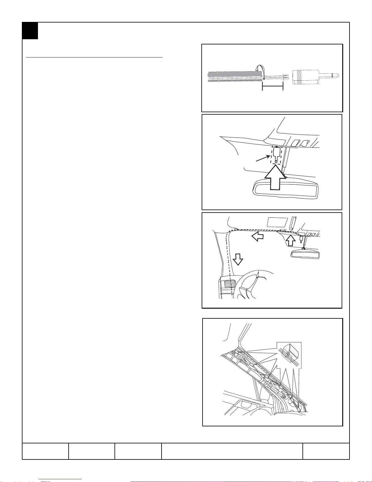
CAUTION:DONOT SECUREANYREMOTE START HARNESSES/MODULES TOANYYELLOWHARNESSES/ CON-
NECTORS(AIRBAGSYSTEM)IN THEVEHICLE.
SSMIII
Diagnostic Interface
Phillips Screwdriver
Short and Standard Wire Cutters PanelRemoval
Tool Alcohol and Towel
: Remove T: TightenTorque
: Install
: Disconnect
: Connect
: Location of Clip or Screw
: Loosen
: Discard
: Re-use
Ratchet and
10mmSocket
WARNING: / AVERTISSEMENT
This vehicle is equipped with a remote controlled engine starter.
To reduce the risk of serious Injury or death, switch engine starter
system into service mode and disconnect the vehicle battery
before performing any service on the vehicle.
Ce véhicule est dotéd'undémarreur à distance. Pour réduire les
risques de blessures graves ou mortelles, mettre le démarreur à
distance en mode service et débrancher la batterie du véhicule
avant d'effectuer des travaux d'entretien sur celui-ci.
RemoteStart
ControlModule
Quantity= 1
RemoteStartIgnition
Wiring Harness
Quantity= 1
Pre-Arranged
Jumper Wiring Harness
Quantity= 1
RemoteStart
Transmitters W/ Warning
Tags
Quantity=2
RemoteStart
Antenna and Harness
Quantity=1
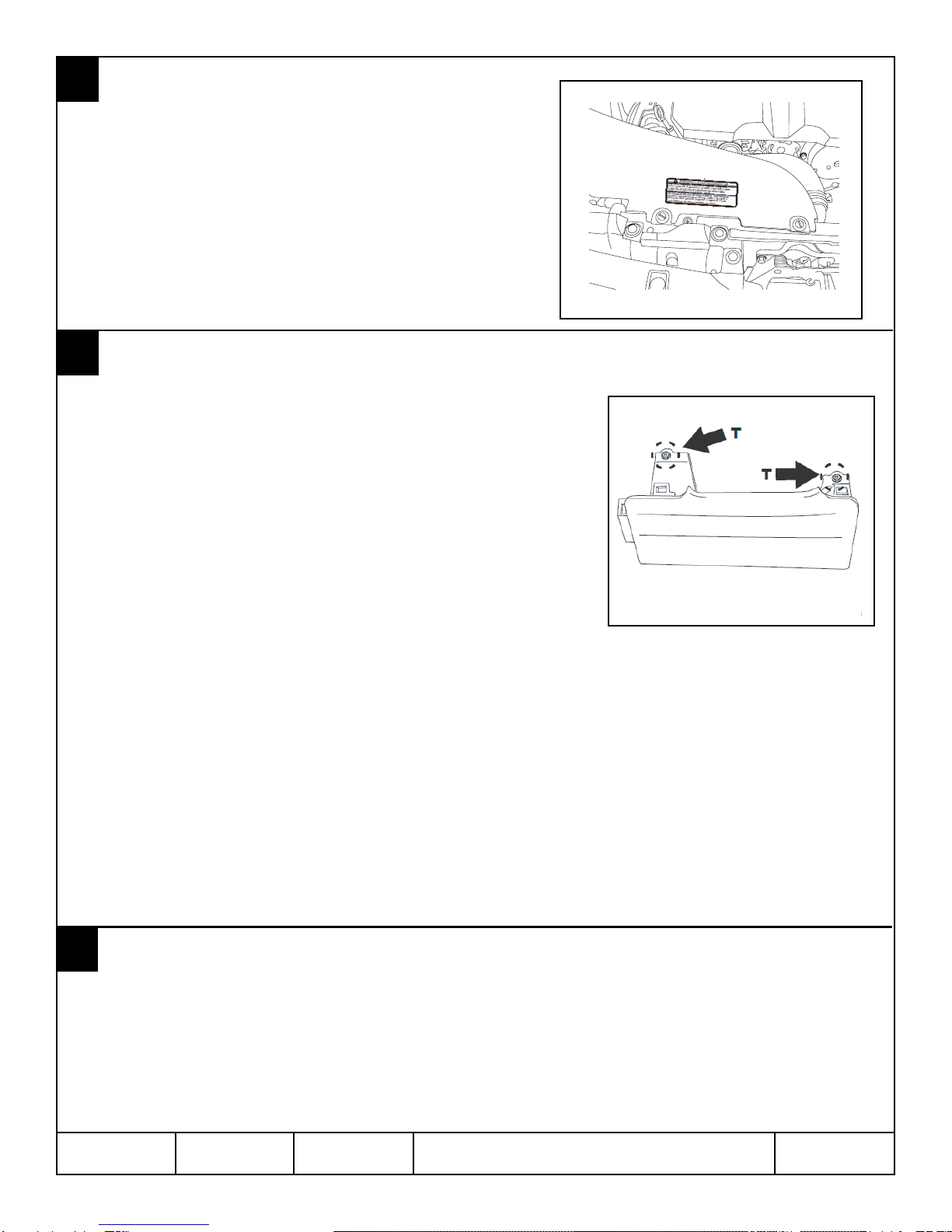
Underhood
Warning Label
Quantity=1
Tie Wraps
8” (Reusable) Quantity= 1
8” Quantity= 15
21” Quantity= 1
StartingYourVehicle
The remote control start function is activated by pressing
the START (key icon) button twice within 3 seconds on
your remote control transmitter. The system will check
certain pre-conditions before starting, and if all safety
parameters are correct, the engine will start within 5
seconds. If the vehiclesstartercranks but does not start
or starts and stalls, the remote engine start system will
power off then attempt to start the vehicle an additional
four times.
WARNING:TOAVOID DANGEROF CARBONMONOXIDE,
NEVERREMOTE STARTAVEHICLE INACLOSED SPACE
SUCHAS ACLOSED GARAGE.
TurningYourVehicle Off
Pressand hold the START (key icon) button again to turn
thevehicle off. If the vehicle is left running the remote start
systemwill allow the vehicle to run for a total of 15 minutes
and then automatically turn off.
Enteringthe VehicleWhile itis Runningvia RemoteStart
1. Unlock the vehicle doors using the factory keyless
remote. If the vehicles doors are unlocked manually
usingthe key, the vehiclessecurity system will trigger
and the remote start system will turn off. Inserting
the ignition key into the ignition cylinder and
turning it to the ON or RUN position will disarm the
security system.
2. Enter the vehicle. Do not press the brake pedal.
3. Insertthe keyinto theignition and turnto theON positi-
ion. If the ignition key is accidently turned to the start
position, the systemsstarteranti-grindfeaturewill
prevent the starter from re-cranking.
4. Press the brake pedal. The remote starter disenga-
ges,the vehicles power window features are re-ena-
bled and the vehicle will operate normally.
RemoteStart
Activation
2Times
RemoteStart
Shutdown
For2Seconds
Press Press
REMOTESTARTQUICK REFERENCE
Quick
Reference Card
Quantity=1English,
1 French
SmallFoamPads
Quantity= 6
Hood Safety Switch,
Mounting Bracket &
MountingBolt
Quantity=1
Long Foam Tape
Quantity= 1
Torque Wrench