Subaru H001SXA000 User manual

1
2
3
KIT CONTENTS
TOOLS REQUIRED
MEANING OF CHARACTERS
PART NUMBER: H001SXA000
DESCRIPTION: REMOTE ENGINE START SYSTEM
INSTALLATION
INSTRUCTIONS
Remote Start Control Module
w/ Software Card and Fuses
Quantity= 1
PART NUMBER
H001SXA000 1 OF 10
ISSUE
01 DATE
03/14/06 SUBARU OF AMERICA
Remote Start
Patch Antenna
Quantity=1
Remote Start Wiring
Harness w/ 30 AMP Fuse
Quantity= 1
Remote Start
Transmitters
Quantity= 2
Remote Start Immobilizer
Interface w/ Antenna Ring
Quantity=1
Installation
Instructions
Quantity=1
Hood Switch Mounting
Bracket, Switch and 10”
Jumper Harness
Quantity=1
Underhood
Warning Label
Quantity=1
Tie Wraps
5” Quantity= 4
8” Quantity= 12
24” Quantity= 1
10 mm Socket
and Ratchet Wire Cutters Electrical Tape
Phillips Screwdriver
Short and Standard Panel Removal
Tool Alcohol and Towel
CAUTION: DO NOT SECURE ANY REMOTE START HARNESSES / MODULES TO ANY
YELLOW HARNESSES / CONNECTORS (AIRBAG SYSTEM) IN THE VEHICLE.
T
: Remove
: Install
: Disconnect
: Connect
: Location of Clip or Screw
: Loosen
: Discard
: Re-use
: Tighten Torque
WARNING: / AVERTISSEMENT
This vehicle is equipped with a remote controlled engine starter.
To reduce the risk of serious Injury or death, switch engine starter
system into service mode and disconnect the vehicle battery
before performing any service on the vehicle.
Ce véhicule est doté d'un démarreur à distance. Pour réduire les
risques de blessures graves ou mortelles, mettre le démarreur à
distance en mode service et débrancher la batterie du véhicule
avant d'effectuer des travaux d'entretien sur celui-ci.
Installation
Instructions
Vehicle Remote Star t System
TM
Featuring P owerCode Technology
Forthe Ultimatein Comfort,Convenience andSecurity
TM
®

4VEHICLE PREPARATION
1. Using a 10mm socket/ratchet, disconnect the negative
battery terminal.
2. Using a panel removal tool, carefully remove the left
side driver’s dash panel cover. (FIGURE A) Using a
phillips screwdriver, remove the plastic screw fastener
securing the left side dashboard panel
(this will be mounted under the previously removed left
side dash panel. (FIGURE B)
3. Using a panel removal tool, carefully remove the driver’s
side lower center console panel. (FIGURE C)
4. Using a phillips screwdriver, remove the 3 plastic phillips
fasteners holding the driver’s under dashboard panel
and leave loose. (FIGURE D)
5. Using a phillips screwdriver, remove the phillips screw
on the underside of the steering column shroud and
carefully unsnap and remove the lower panel. Be careful
not to damage the lower dashboard panel. (FIGURE E)
PART NUMBER
H001SXA000 2 OF 10
ISSUE
01 DATE
03/14/06 SUBARU OF AMERICA
FIGURE A
FIGURE B
FIGURE C
FIGURE D
FIGURE E

PART NUMBER
H001SXA000
3 OF 10
ISSUE
01 DATE
03/14/06 SUBARU OF AMERICA
6. Using a panel removal tool, un-clip and remove the
driver’s side lower dashboard panel and un-plug any
connectors. (FIGURE F)
7. Unplug the diagnostic plug by releasing the side clip on
the connector. Unplug the 2-way connector for the
under dashboard light and remove the driver’s under
dashboard panel. (FIGURE G)
8. Unplug the 2-way connector and air tube connected to
the right side of the metal knee bolster. Remove the
metal knee bolster by removing the (4) 10mm bolts.
(FIGURE H)
FIGURE F
FIGURE G
FIGURE H
VEHICLE PREPARATION (CONTINUED)
WINDSHIELD MOUNT ANTENNA INSTALLATION
5
1. Locate the position at the top of the windshield 1” left
of center and 1” from top of headliner. (FIGURE I)
2. Using alcohol clean the area thoroughly.
3. Remove the adhesive backing on the antenna
assembly and apply the antenna to the windshield in
the area indicated above. (FIGURE I)
4. Using a panel removal tool, carefully remove the
airbag labeled cap at the top of the A-pillar and
remove the 10mm bolt. (FIGURE J)
5. Gently remove the A-pillar panel starting at the top
releasing the pressure clip at the bottom of the panel.
(FIGURE J)
FIGURE I
FIGURE J

WINDSHIELD MOUNT ANTENNA INSTALLATION (CONTINUED)
PART NUMBER
H001SXA000 4 OF 10
ISSUE
01 DATE
03/14/06 SUBARU OF AMERICA
FIGURE K
6. Route the antenna cable under the headliner
and down the A-pillar securing into the
plastic clips holding the sunroof drain tube.
Route the cable to the opening on the left
side of driver’s dashboard. The antenna
cable will be plugged into the remote start
control module later. (FIGURE K)
7. Reinstall the A-pillar panel. Torque the 10mm
bolt to 10.8Nm +/- 2Nm (1.10 Kgf-m+/- 0.2
Kgf-m, 8 ft-lbs +/- 1.5 ft-lbs). (FIGURE J)
MAIN HARNESS CONNECTIONS
6-WAY IGNITION SWITCH CONNECTIONS
1. Locate the 6-pin ignition switch connector on the
left side of the steering column and unplug.
(FIGURE L)
2. Plug the remote start harness 6-pin female ignition
switch connector into the vehicle’s ignition switch
and plug the previously unplugged vehicle’s female
ignition switch connector into the remote start
harness 6-pin male ignition switch connector.
(FIGURE M)
3. Using 2 of the supplied 8” tie wraps, secure the
remote start harness wiring to the existing vehicle
wiring, making sure that it will not interfere with the
operation of the tilt steering column and re-
assembly of vehicle panels. (FIGURE N)
6
FIGURE M
FIGURE L
FIGURE N

MAIN HARNESS CONNECTIONS (CONTINUED)
24-PIN AND 2-PIN UPPER LEFT KICK PANEL PRE-
FIT CONNECTIONS
1. Locate the vehicle’s 24-pin and 2-pin pre-fit
connections located in the upper left kick panel area.
These connectors are secured to the vehicle wiring
using breakaway tape. (FIGURE O)
2. When the 2-pin pre-fit connector is located, unplug
and discard the mating wire jumper.
3. Carefully route the remote start harness 24-pin and
2-pin connectors to the upper left kick panel area,
making sure that they will not interfere with any
vehicle moving components and re-assembly of
dashboard panels. (FIGURE P)
4. Plug the remote start harness 24-pin and 2-pin
males connectors into the corresponding 24-pin and
2-pin vehicle female connectors.
5. Using 2 of the supplied 8” tie wraps, secure the
remote start wiring to existing vehicle wiring.
6. Route the remote start harness programming button
and 30-AMP fuse assembly to the vehicles fuse box
assembly and secure the wiring to existing vehicle
wiring using one of the supplied 8” tie wraps.
(FIGURE Q). DO NOT SECURE THE REMOTE
START HARNESS TO ANY VEHICLE YELLOW
HARNESSES / CONNECTORS (AIRBAG SYSTEM).
PART NUMBER
H001SXA000 5 OF 10
ISSUE
01 DATE
03/14/06 SUBARU OF AMERICA
FIGURE P
FIGURE O
FIGURE Q

CONTROL MODULE CONNECTION & MOUNTING / IMMOBILIZER INTERFACE MOUNTING
1. Route the previously installed antenna cable towards the
remote start harness 24-pin, 16-pin and 10-pin
connectors. At the top of the steering column secure the
antenna cable along the way with 2 of the supplied 8” tie
wraps.
2. Plug the 24-pin, 16-pin and 10-pin connectors into the
front of the remote start control module making sure the
connectors are completely seated (they will only fit into
the control module one way). (FIGURE R) Plug the 2-pin
antenna cable connector into the 2-pin port on the back
of the remote start control module. NOTE: The small 4-
pin and 5-pin connectors on the control module are not
used.
PART NUMBER
H001SXA000 6 OF 10
ISSUE
01 DATE
03/14/06 SUBARU OF AMERICA
7
FIGURE S
24-Way 10-Way
Antenna
16-Way
FIGURE R
IMMOBILIZER INTERFACE MOUNTING
1. Locate the A/T Control Module to the left of the brake
pedal. Using alcohol, clean an area on the A/T control
module metal bracket. Using the supplied velcro and 24”
tie wrap, secure the immobilizer interface to the A/T
Control Module. (FIGURE T)
2. Plug in 4 pin immobilizer interface connector (in harness)
to 4 pin connector on interface box. (FIGURE T)
REMOTE ENGINE START CONTROL MODULE
MOUNTING
1. Locate the vehicle’s body integrated unit (BIU) mounted to
the bulkhead between the gas pedal and steering column.
2. Using alcohol clean the area on the right side of the BIU.
Remove the adhesive backing on the back of the remote
start control module.
3. Secure the remote start control module to the right side of
the BIU making sure the 3 connectors on the remote start
control module are pointing towards the rear of the
vehicle. (FIGURE S)
4. As a secondary mounting provision, secure the remote
start control module to the BIU using the supplied 24” tie
wrap.
FIGURE T
BIU

PART NUMBER
H001SXA000
7 OF 10
ISSUE
01 DATE
03/14/06 SUBARU OF AMERICA
8
1. Locate the 2 phillips screws at the steering column
that secure the upper steering column shroud to the
steering column assembly. Refer to FIGURE U for
location reference.
2. Using a phillips screwdriver, loosen but do not
remove the 2 phillips screws. (FIGURE V)
3. Locate the illuminated ignition cylinder ring and
gently slip the immobilizer interface antenna ring
behind the illuminated ring and behind the upper
steering column shroud. Re-secure the previously
loosened phillips screws securing the upper steering
column shroud to the steering column assembly.
(FIGURE W)
4. Route the immobilizer interface antenna ring wiring
to the left side of the steering column and down the
steering column and plug into the 2-pin port on the
immobilizer interface (refer back to FIGURE T).
Secure the immobilizer interface antenna ring wiring
to the existing vehicle wiring and remote start
harness using 2 of the supplied 5” tie wraps. Be
sure to route wiring to avoid the lower steering
column shroud screw hole and any steering column
moving parts. (FIGURE X)
IMMOBILIZER INTERFACE ANTENNA RING MOUNTING
FIGURE V
FIGURE W
FIGURE X
FIGURE U

HOOD SAFETY SWITCH MOUNTING
1. In the engine compartment, locate the 2-pin pre-fit
hood safety switch connector secured to the wire
harness with breakaway tape in front of the shock
tower on the passenger’s side of the vehicle.
(FIGURE Y)
2. Plug the supplied remote start harness 10” hood
safety switch wiring harness to the vehicle’s 2-pin
pre-fit connector.
3. Mount the hood safety switch bracket to the
vehicle’s fender in the predrilled hole using the
supplied 10mm bolt (FIGURE Z). Torque the bolt to
10.8 Nm +/- 2 Nm (1.10 Kgf-m +/- 0.2 Kgf-m, 8 ft-lbs
+/- 1.5 ft-lbs).
4. Securely mount (snap-in) the supplied hood safety
switch in the bracket and plug the 2-way female
connector of remote start harness 10” hood safety
switch wiring harness to the base of the hood safety
switch. (FIGURE Z)
PART NUMBER
H001SXA000 8 OF 10
ISSUE
01 DATE
03/14/06 SUBARU OF AMERICA
9
FIGURE Y
FIGURE Z
T
UNDER HOOD WARNING LABEL MOUNTING
1. Using alcohol clean the top of the air intake plenum.
2. Remove the adhesive backing of the underhood
warning label and secure to the top of the air intake
plenum. (FIGURE AA)
10
WARNING: / AVERTISSEMENT
This vehicle is equipped with a remote controlled engine starter.
To reduce the risk of serious Injury or death, switch engine starter
system into service mode and disconnect the vehicle battery
before performing any service on the vehicle.
Ce véhicule est dotéd'un démarreur àdistance. Pour réduire les
risques de blessures graves ou mortelles, mettre le démarreur à
distance en mode service et débrancher la batterie du véhicule
avant d'effectuer des travaux d'entretien sur celui-ci.
FIGURE AA

TACHOMETER IDLE SPEED PROGRAMMING
1. Open driver’s door (leave open throughout programming operation).
2. Turn the ignition key to the ON or RUN position.
3. Press and hold the momentary programming button for approximately 10 seconds until the
vehicle’s horn honks (3) times.
4. Release the momentary programming button.
5. Press and release the momentary programming button. The vehicle’s horn will honk (4)
times.
6. Press and release the vehicle’s brake pedal (1) time. The horn will honk (1) time to
indicate that the system has entered tachometer idle speed programming mode.
7. Start the vehicle with the ignition key. The RES system will begin honking the vehicle’s
horn 1 time every 3 seconds to indicate a valid tach signal.
8. When the engine has settled to a normal idle speed (normally 750-1000 RPM), press and
release the brake pedal (1) time. The horn will honk (2) times to indicate the system has
exited tach idle speed programming.
Be sure that the vehicle has maintained 750-1000 RPM idle speed prior to exiting
tachometer idle speed programming.
9. Turn the ignition key to the OFF position.
SYSTEM POWER-UP
After all connections are complete, turn the ignition key to the ON or RUN
position and re-connect the vehicle’s negative battery terminal.
PART NUMBER
H001SXA000 9 OF 10
ISSUE
01 DATE
03/14/06 SUBARU OF AMERICA
11
12

IMMOBILIZER INTERFACE PROGRAMMING
NOTE: The immobilizer interface will be programmed to the vehicle as an ignition key
1. Plug the “Subaru Diagnostic Interface” (SDI) cable into the vehicle’s diagnostic plug.
2. Turn one of the ignition keys to the RUN position.
3. Press the SDI Menu and C buttons until the SDI enters into “Stand Alone Mode”.
4. Using the arrows on the SDI, select Subaru Vehicle and press enter.
5. On the SDI screen select “IMM Regist” using the arrows and then press enter.
6. The screen will display “Execute Key Reg?”, press enter.
7. The SDI screen will prompt for the 4-digit teaching operation code (this is a number specific to the B9 Tribeca). Using the
arrows, enter the teaching operation code and press enter.
8. The SDI screen will prompt for the 5-digit security ID (this number is vehicle specific and is located on the large metal tag
attached to the vehicle’s keys). Using the arrows, enter the vehicle specific security ID and press enter.
9. The SDI screen will display “Registering Key”. After registration is complete, the SDI screen will display “Program 2nd
Key”, press enter.
10. The SDI screen will display “Key Change”, turn the ignition OFF and turn the ignition ON using the 2nd key.
11. The SDI screen will display “Register Key?”, press enter.
12. The SDI screen will display “Registering Key”. After registration is complete, the SDI screen will display “Program 3rd
Key”, press enter.
13. The SDI screen will display “Key Change”, turn the ignition OFF and turn the ignition ON using the 3rd key.
14. The SDI screen will display “Register Key?”, press enter.
15. The SDI screen will display “Registering Key”. After registration is complete, the SDI screen will display “Program 4th
Key”, press enter.
16. The SDI screen will display “Key Change”, turn the ignition OFF and remove the 3rd key.
17. Press and release the remote start system programming button one time to access “Immobilizer Interface Registration
Mode”.
18. Activate the remote start system by pressing the transmitter START (key icon) button (2) times.
19. The ignition will power and the SDI will display “Register Key?”, press enter.
20. The SDI screen will display “Registering Key”. After complete, the SDI screen will display “Ending Key Reg”, press the
vehicle’s brake pedal (1) time to exit “Immobilizer Interface Registration Mode” and turn the vehicle’s ignition off.
NOTE: The above steps assume that all (3) vehicle ignition keys are available at time of installation. If any keys are not present
during programming, they will not operate the vehicle after these steps are completed.
PART NUMBER
H001SXA000 10 OF 10
ISSUE
01 DATE
03/14/06 SUBARU OF AMERICA
13
NOTE: IF YOU DID NOT PROGRAM THE VEHICLE’S TACH IDLE SPEED AS INSTRUCTED IN STEP 12, THEN THE VEHICLE WILL NOT
ATTEMPT TO START, INSTEAD YOU WILL GET THREE ADDITIONAL BEEPS FROM THE HORN. THE RES SYSTEM MUST LEARN A
VALID IDLE SPEED PRIOR TO ATTEMPTING TO PROGRAM THE IMMOBILIZER INTERFACE.
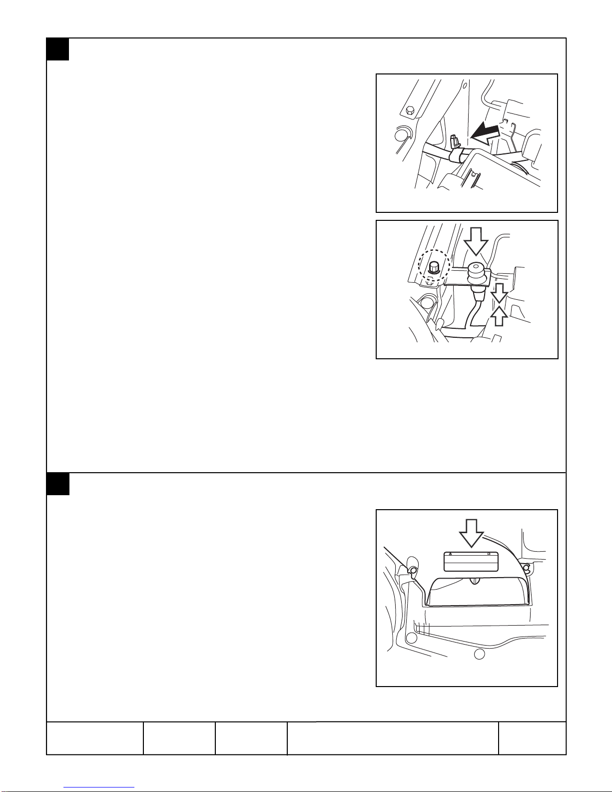
PANEL RE-ASSEMBLY
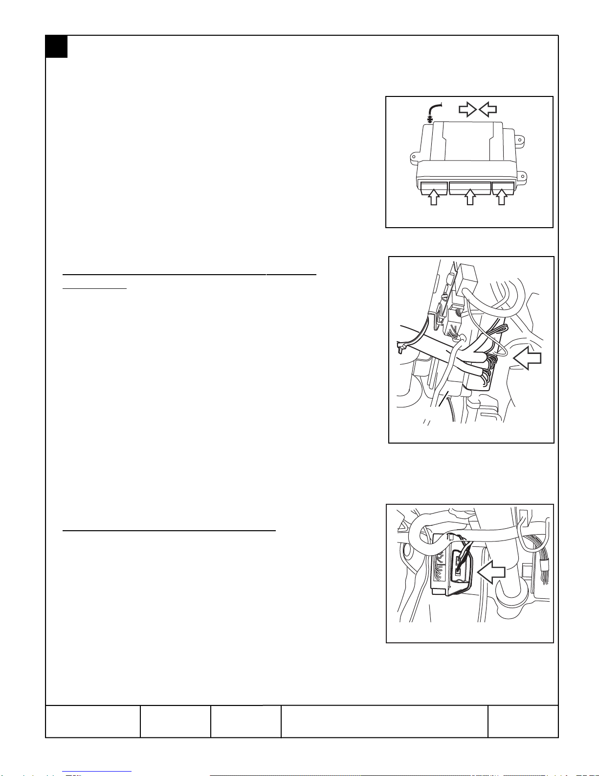
1. Re-install knee bolster panel and torque the 10mm bolts to 10.8
Nm +/- 2 Nm (1.10 Kgf-m +/- 0.2Kgf-m, 8ft-lbs +/- 1.5 ft-lbs)
and plug in the 2-way connector and air tube. (FIGURE BB)
2. Plug any previously removed connectors and re-install the driver’s
side lower dashboard panel. Secure in place with the phillips
fasteners on the side of dashboard opening (refer to FIGURES B
& F).
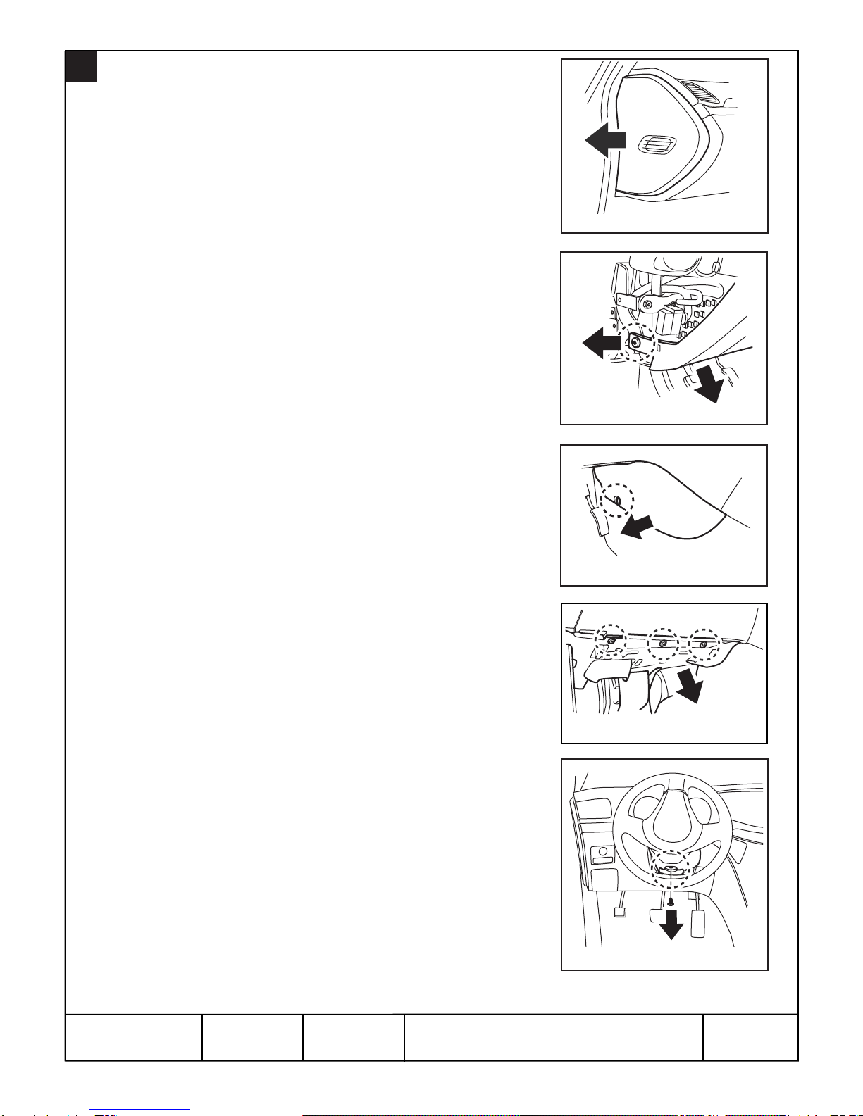
3. Plug in diagnostic plug and under dashboard light connector and
reinstall the driver’s side under dashboard panel, securing in
place with the (3) phillips fastener (refer to FIGURE D).
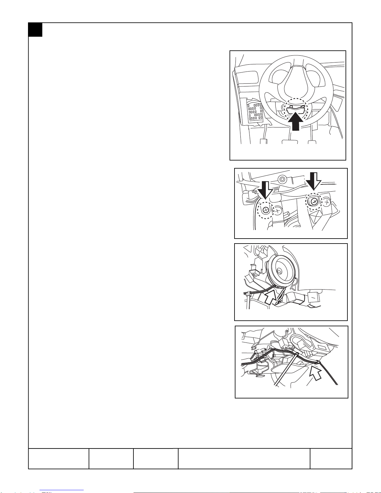
4. Re-install the steering column shroud and secure with the phillips
screw (refer to FIGURE E).
5. Re-install the drivers side lower center console panel
(refer to FIGURE C).
6. Re-install the left side driver’s dashboard panel (refer to FIGURE A).
14
TT
FIGURE BB
Table of contents
Other Subaru Remote Starter manuals

Subaru
Subaru H001SFL400 User manual

Subaru
Subaru Remote Start User manual

Subaru
Subaru H011SAJ400 User manual

Subaru
Subaru H001SSG400 User manual

Subaru
Subaru H7110FS101 User manual

Subaru
Subaru H001SFJ800 User manual

Subaru
Subaru H001SFJ600 User manual

Subaru
Subaru H001SVA800 User manual

Subaru
Subaru H001SFL300 User manual

Subaru
Subaru LEGACY H7110LS200 User manual