Subaru H011SAJ400 User manual

1 OF 11
PARTNUMBER
H011SAJ400 ISSUE
00 DATE
21Apr2013 SUBARUOFAMERICA
PARTNUMBER: H011SAJ400
DESCRIPTION: REMOTEENGINESTARTSYSTEM
INSTALLATION
INSTRUCTIONS
WARNING: / AVERTISSEMENT
This vehicle is equipped with a remote controlled engine starter.
To reduce the risk of serious Injury or death, switch engine starter
system into service mode and disconnect the vehicle battery
before performing any service on the vehicle.
Ce véhicule est dotéd'undémarreur à distance. Pourréduire les
risques de blessures graves ou mortelles, mettre le démarreur à
distance en mode service et débrancher la batterie du véhicule
avant d'effectuer des travaux d'entretien sur celui-ci.
1
2
3
KIT CONTENTS
TOOLS REQUIRED
MEANING OF CHARACTERS
CAUTION:DONOTSECUREANYREMOTE STARTHARNESSES / MODULES TOANYYELLOW HARNESSES / CON-
NECTORS(AIRBAGSYSTEM) IN THE VEHICLE.
RemoteStart
ControlModule
Quantity= 1
RemoteStartIgnition
Wiring Harness
Quantity= 1
Pre-Arranged
Jumper Wiring Harness
Quantity= 1
RemoteStart
Transmitters
Quantity=2
Remote StartHood Safety
Switch and Mounting Bracket
Quantity=1
RemoteStart
Antenna and Harness
Quantity=1
Underhood
Warning Label
Quantity=1
Tie Wraps
8” Quantity= 8
21” Quantity= 1
SSMIII
Diagnostic Interface
Phillips Screwdriver
Short and Standard Wire Cutters PanelRemoval
Tool Alcohol and Towel
: Remove T: TightenTorque
: Install
: Disconnect
: Connect
: Location of Clip or Screw
: Loosen
: Discard
: Re-use
StartingYourVehicle
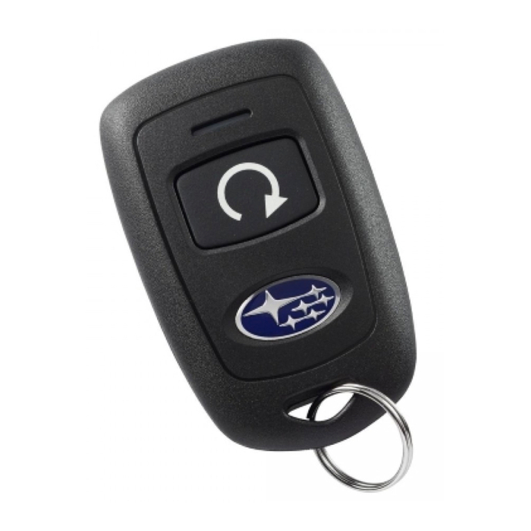
The remote control start function is activated by pressing
the START (key icon) button twice within 3 seconds on
your remote control transmitter. The system will check
certain pre-conditions before starting, and if all safety
parameters are correct, the engine will start within 5
seconds. If the vehiclesstartercranks but does not start
or starts and stalls, the remote engine start system will
power off then attempt to start the vehicle an additional
four times.
WARNING:TOAVOID DANGEROF CARBONMONOXIDE,
NEVERREMOTE STARTAVEHICLE INACLOSED SPACE
SUCHAS ACLOSED GARAGE.
TurningYourVehicle Off
Pressand hold the START (key icon) button again to turn
thevehicle off. If the vehicle is left running the remote start
systemwill allow the vehicle to run for a total of 15 minutes
and then automatically turn off.
Enteringthe VehicleWhile itis Runningvia RemoteStart
1. Unlock the vehicle doors using the factory keyless
remote. If the vehicles doors are unlocked manually
usingthe key, the vehiclessecurity system will trigger
and the remote start system will turn off. Inserting
the ignition key into the ignition cylinder and
turning it to the ON or RUN position will disarm the
security system.
2. Enter the vehicle. Do not press the brake pedal.
3. Insertthe keyinto theignition and turnto theON positi-
ion. If the ignition key is accidently turned to the start
position, the systemsstarteranti-grindfeaturewill
prevent the starter from re-cranking.
4. Press the brake pedal. The remote starter disenga-
ges,the vehicles power window features are re-ena-
bled and the vehicle will operate normally.
RemoteStart
Activation
2Times
RemoteStart
Shutdown
For2Seconds
Press Press
REMOTESTARTQUICK REFERENCE
Quick
Reference Card
Quantity=1
A-PillarTrimClip
Quantity= 1
FoamTape
Quantity= 5
Ratchet and
10mmSocket
2 OF 11
PARTNUMBER
H011SAJ400 ISSUE
00 DATE
21Apr 2013 SUBARUOFAMERICA
1. Using a 10 mm socket/ratchet, disconnect the negative battery
terminal.
2. Using a phillips screwdriver, remove the two (2) plastic phillips
fasteners and one (1) pressure fastener (left side) holding the
driver’s side under dashboard panel. Release the diagnostic
connectorby pressingthe sideclip onthe connectorand remove
thedriver’sside under dashboard panel. (FIGUREA)
3. Usingapanelremovaltool,carefullyremovetheleftsidedashboard
panel (FIGURE B). Remove 2 screws securing the lower
dashboardpanel on the left side of the dashboard. (FIGURE C)
4. Removeone(1) phillipsscrewsecuring thelower right sideof the
driver’sdashboard panel. (FIGURE D)
5. Using a panel removal tool, carefully remove the driver’s side
lower dashboard panel (the right side pulls out and down) and
unplugthe connectors on the left side and the connectorand air
tube on the right side of the dashboard panel (if required).
(FIGUREE)
6. Using a 10 mm socket/ratchet, remove the 2 bolts securing the
driver’ssidedashboard knee bolster. (FIGUREF)
7. Remove the lower steering column shroud using a phillips
screwdriver, remove one (1) phillips screw on the left side face
and one (1) phillips screw on the right side face of the steering
columnshroudandcarefullyunsnapandremovethelowersteering
column shroud panel (FIGURE G). NOTE: You will need to
rotate the steering wheel to access the phillips screws on the
face of the steering column.
4VEHICLE PREPARATION
FIGUREC FIGURE D
FIGUREB
FIGUREA
FIGUREE
FIGUREG
FIGUREF

3 OF 11
PARTNUMBER
H011SAJ400 ISSUE
00 DATE
21Apr 2013 SUBARUOFAMERICA
5WINDSHIELD MOUNT ANTENNA INSTALLATION
ANTENNAPODMOUNTING-VEHICLESWITHOUTEYESIGHT
1. Locatethe positionat thetop ofthe windshield25 mm left of
centerand 19 mm down fromthe headliner. Usealcoholto
cleanthe area thoroughly.
2. Removetheadhesivebacking on theantennapodand apply
the antenna to the windshield in the area indicated above.
Notethebase oftheantenna pod(harness connection end)
shouldline up to thearea of the windshieldwhere the solid
black film and dotted black film meet. (FIGURE H)
ANTENNAPODMOUNTING-VEHICLES WITH EYESIGHT
1. Mount the antenna pod to the top left hand side of the
windshield, against the headliner near the driver’s sideA-
pillar trim panel with the antenna pod “finger” facing the
passenger’sside. Usealcoholto cleanthearea thoroughly.
2. The top left corner of the antenna pod should be 10 mm
away from the top right corner of the A pillar panel in a
straight line. Note: the antenna pod base should be level
left to right, not parallel to the headliner contours.
3. Removetheadhesivebacking on theantennapodand apply
theantenna tothe windshieldin thearea indicatedin step2
above. (FIGUREI)
FIGUREH
10 mm
Sunvisor
FIGUREI

4 OF 11
PARTNUMBER
H011SAJ400 ISSUE
00 DATE
21Apr 2013 SUBARUOFAMERICA
5WINDSHIELD MOUNT ANTENNA INSTALLATION
A-PILLARPANELREMOVAL
1. CarefullyprytheA-pillartrimpanelawayfromthewindshield
andcut-offtheupperA-pillartrim clipusing diagonalpliers.
(FIGUREJ). Remove theA-pillar paneland setaside.
2. Slideaflatbladescrewdriverunderneaththevehicle’sairbag
and between the clip and the vehicle’s body. Twist the flat
blade screwdriver until you hear a click sound, indicating
thereleaseofthelowersidesnap. (FIGUREK) CAUTION!
Use care when performing this step to avoid damage
to the curtain airbag. If the airbag is damaged, it
must be replaced.
3. Slidethe flatblade screwdriver further along the side of the
clip. Twist the flat blade screwdriver until you hear the
clicksound, indicating the release of the upper side snap.
(FIGUREL) CAUTION! Use care when performing this
step to avoid damage to the curtain airbag. If the
airbag is damaged, it must be replaced.
4. Removetheclipfromthe vehicle’s body(theclipwill remove
easier if it is twisted while it is pulled). (FIGURE M)
5. Inspectthewhiteprotective(non-wovenfabric)ofthe curtain
airbag. If the fabric is damaged, indicated by the visibility
ofthepinkairbagmodulecloth, the curtainairbagassembly
must be replaced.
FIGUREJ
FIGUREK
FIGUREL FIGUREM

5 OF 11
PARTNUMBER
H011SAJ400 ISSUE
00 DATE
21Apr 2013 SUBARUOFAMERICA
5WINDSHIELD MOUNT ANTENNA INSTALLATION, continued
ANTENNAPODMOUNTING/HARNESSROUTING
1. Wrap one (1) piece of the supplied foam tape around the
antenna harness 76 mm from the connector and a second
piece 152 mm away from the first piece of foam tape.
(FIGUREN)
2. Plugthe5-pin connectoron theantenna harness intothe 5-
pinport on the antenna pod. (FIGUREN)
3. Vehicles without Eyesight - Route the antenna harness
acrosstheheadliner anddown theA-pillartucking thecable
belowthedriver’ssidedashboardthroughtheopeningclosest
tothewindshieldandallowtheharnesstohangloosebehind
thevehicle’sdashboardmountedfusebox. (FIGURE O) The
antennaharnesswillbepluggedintothe remote startcontrol
module later. Note: Use care to ensure that there is no
stress on the antenna harness at the antenna pod
connection point and verify the harness is routed in a
manner to avoid sharp edges or interference with panel
re-installation.
4. Vehicles withEyesight - Routethe antennaharness directly
intoanddowntheA-pillartuckingthecablebelowthedriver’s
side dashboard through the opening closest to the
windshieldand allow theharness to hang loose behind the
vehicle’s dashboard mounted fusebox. (FIGURE P) The
antennaharnesswillbepluggedintothe remote startcontrol
module later. Note: Use care to ensure that there is no
stress on the antenna harness at the antenna pod
connection point and verify the harness is routed in a
manner to avoid sharp edges or interference with panel
re-installation.
5. Securethe antennaharness to the existing vehiclewiring in
theA-pillarin three (3) placesusingthesupplied8”tiewraps.
Wrap the tie wraps with the supplied foam tape to prevent
rattling. (FIGUREP)
6. Install the supplied A-pillar trim clip and re-install the A-
pillarpanel. (FIGURE Q)
6"
3"
FIGUREN
FIGURE O
FIGURE Q
FIGUREP

6 OF 11
PARTNUMBER
H011SAJ400 ISSUE
00 DATE
21Apr 2013 SUBARUOFAMERICA
FIGURET
FIGUREU
Pre-fit
Connectors
6
6-PINIGNITIONSWITCHCONNECTIONS
1. Locate the 6-pin ignition switch connector on the right side of the steering
columnand unplug. (FIGURER)
2. Plugthepreviouslyunplugged vehicle’sfemaleignitionswitch connectorinto
theremote startignition harness 6-pin male connector. (FIGURES)
3. Plugtheremotestartignitionharness6-pinfemaleconnectorintothevehicle’s
ignition switch. (FIGURE S)
4-PIN&2-PINPRE-FITCONNECTIONSABOVE&BEHINDFUSEPANEL
1. Locate the vehicle’s 4-pin and 2-pin pre-fit connections located behind the
fusepanel to theleft ofthe steeringcolumn. These connectors aresecured
tothe vehiclewiring using breakaway tape. (FIGURE T)
2. When the 2-pin pre-fit connector is located, unplug and discard the mating
wirejumper. (Thisis usedfor the power window interruptcircuit)
3. Plugtheremote start pre-fitjumper harness 4-pinand2-pin maleconnectors
into the corresponding 4-pin and 2-pin vehicle female connectors.
(FIGUREU)
MAIN HARNESS CONNECTIONS
FIGURER
FIGURES

7 OF 11
PARTNUMBER
H011SAJ400 ISSUE
00 DATE
21Apr 2013 SUBARUOFAMERICA
7
1. Locatethe vehicle’sautomatic transmission (A / T) module mounted
to the left side of the steering column. (FIGURE V)
2. Route the previously installed windshield mounted antenna harness
and previously installed remote start pre-fit jumper harness towards
theA / T module and plug into the corresponding connectors on the
remote start control module (FIGURE W). Route the remote start
ignition harness towards the A / T module and plug into the
corresponding connector on the remote start control module
(FIGURE W). Double check all connectors to ensure a secure fit.
3. Secure the remote start control module to the left side of the A / T
moduleusingthesuppliedvelcro making suretheremotestartignition
harnessconnectoris facingdown (samedirectionas theA/Tmodule
connector). (FIGUREX)
4. As a secondary mounting provision, secure the remote start control
module to theA/ T module using the supplied 21” tie wrap (route the
tiewrap between the 12-pin and5-pin connectorson theremote start
controlmoduleand throughtheright sideof theA/Tmodulebracket).
(FIGUREX)
5. Using the supplied 8” tie wrap, secure excess remote start jumper
harnessandantennaharnesswiringtothe existing vehicle wiringnear
theprefit connectors behind the fusebox. (FIGUREY)
6. Using a supplied 8” tie wrap, secure the mated remote start harness
6-pinmaleandvehicle’s6-pinfemaleconnectorsto the factory ignition
harness. (FIGUREZ)
7. Route the remote start ignition harness down the right side of the
steering column following the factory ignition harness and secure to
thefactory ignition harness in two(2) places using the supplied8” tie
wraps(FIGUREZ).
NOTE: After the remote start control module has been mounted
and all wiring secured, operate the tilt / telescopic fully to ensure
that the new components do not interfere with operation of the
tilt / telescopic feature.
REMOTE START CONTROLMODULE MOUNTING
FIGURE W
FIGUREX
Ignition Harness
Connector
Jumper Harness
Connector Antenna Harness
Connector
FIGUREV
A/T Module
BrakePedal
A/T Module
BrakePedal
Tie Wrap
FIGUREZ
FIGUREY
RESModule

8 OF 11
PARTNUMBER
H011SAJ400 ISSUE
00 DATE
21Apr 2013 SUBARUOFAMERICA
8HOOD SAFETY SWITCH MOUNTING
1. Inthe engine compartment, locatethe 2-pin pre-fit hood safetyswitch
connectorsecured tothe wireharness withbreakaway tape along the
framerail on the passenger’sside of the vehicle (FIGUREAA).
2. Loosenslightlythe rear (topmounted)10mm boltandremovethe front
mounted 10mm bolt securing the power steering fluid reservoir tank
andmove the power steering reservoir tank slightly for easier access
to the 2-pin pre-fit hood safety switch connector. (FIGURE BB)
3. Mount the hood safety switch bracket behind the power steering
reservoirtankmountmakingsurethemounting bolt holeonthebracket
linesup with mounting bolthole on the power steering reservoir tank.
(FIGURECC)
4. Reinstall the front 10mm mounting bolt and re-tighten the rear (top
mounted) 10mm mounting bolt. Torque both mounting bolts to 10.8
Nm +/- 2 Nm (1.10 Kgf-m +/- 0.2 Kgf-m, 8 ft-lbs +/- 1.5 ft-lbs).
5. Securely mount (snap-in) the supplied hood safety switch into the
bracketandplugthevehicle’spre-fit2-pinfemalehoodswitchconnector
to the base of the hood safety switch. (FIGURE CC)
9UNDER HOOD WARNING LABEL MOUNTING
1. Using alcohol clean the top of the air intake plenum.
2. Removetheadhesivebackingoftheunderhoodwarning
label and secure to the top of the air intake plenum.
(FIGUREDD)
FIGURE DD
WARNING: / AVERTISSEMENT
This vehicle is equipped with a remote controlled engine starter.
To reduce the risk of serious Injury or death, switch engine starter
system into service mode and disconnect the vehicle battery
before performing any service on the vehicle.
Ce véhicule est doté d'un démarreur à distance. Pour réduire les
risques de blessures graves ou mortelles, mettre le démarreur à
distance en mode service et débrancher la batterie du véhicule
avant d'effectuer des travaux d'entretien sur celui-ci.
FIGUREAA
FIGUREBB
FIGURE CC

9 OF 11
PARTNUMBER
H011SAJ400 ISSUE
00 DATE
21Apr 2013 SUBARUOFAMERICA
SYSTEM POWER-UP
1. Afterallconnections are complete, re-connect thevehicle’s negativebattery terminal.
2. Start the vehicle a minimum of one (1) time using the ignition key prior to activating the remote engine start system.
This is required to allow the vehicle electronic systems to re-synchronize.
11
PANEL RE-ASSEMBLY
10
1. Reinstall the knee bolster and torque the bolts to 10.8 Nm +/- 2 Nm
(1.10Kgf-m +/- 0.2 Kgf-m, 8 ft-lbs +/- 1.5 ft-lbs). (FIGURE EE)
2. Reinstallthesteering column shroud and secure in placewith two(2)
phillipsscrews. (refer to FIGURE G)
3. Plug in any previously removed connectors and re-install the lower
dashboardpanel(refer toFIGUREE).
4. Re-install one (1) phillips screw on the lower right side of the driver’s
dashboardpanel. (referto FIGURED)
5. Re-installthe two (2) phillipsscrews on the left sideof the dashboard
thatsecure the lower dashboard panelin place. (refer to FIGURE C)
6. Re-installtheleft side dashboard panel. (refer to FIGURE B)
7. Re-install the diagnostic connector and under dashboard panel and
securewiththe two (2)phillipsfastenersandone (1)pressurefastener.
(refertoFIGUREA)
8. At the end of the installation, insert the Quick Reference Card into the
Owner’sInformationKit.
FIGUREEE
TT

10 OF 11
PARTNUMBER
H011SAJ400 ISSUE
00 DATE
21Apr 2013 SUBARUOFAMERICA
SYSTEM REGISTRATION
12
NOTE: ALL VEHICLE IGNITION KEYS MUST BE AVAILABLE WHEN THE SYSTEM REGISTRA-
TION PROCESS IS COMPLETED.
SDI SETUP
REGISTRATION SETUP
2nd KEY REGISTRATION
3rd KEY REGISTRATION
REMOTE START REGISTRATION
SDI screen will
display “Key reg
OK Reg 2nd key?"
SDI screen will
display “IG OFF Key
Change”. Remove
first key, insert 2
nd
key and cycle to RUN
SDI screen will
display “Execute
Key Reg?" ENTER SDI screen will
display
“Registering Key
SDI screen will
display "Reg
Remote Cont Eng.
Starter?"
Turn the ignition key to the OFF position
and remove from the ignition cylinder.
Press ENTER to exit registration
Plug the SDI
diagnostic plug
into the vehicles
diagnostic
connector
Insert any ignition
key into the
ignition cylinder
and turn to the
RUN position
Press and hold the SDI
“Menu” and “C” buttons
simultaneously for
approximately 5 seconds
to enter stand alone mode
Proceed to
“Registration
Setup”
SDI screen prompts for
the 4-digit teaching
operation code. Enter
the code using the
arrows on the SDI
SDI screen prompts for
the5-digit security ID
(vehicle specific). Enter
the code using the
arrows on the SDI
ENTER ENTER SDI screen will
display
“Registering Key
Proceed to "2
nd
Key
Registration" or press "C"
and proceed to "Remote
Start Registration" if no
additional keys are
available
The SDI screen
will display
“Execute Key
Reg?"
SDI screen will
display
“Execute Key Reg"
ENTER ENTER
Proceed to "3
rd
Key
Registration" or press "C"
and proceed to "Remote
Start Registration" if no
additional keys are
available
Proceed to "4
th
Key
Registration" or press "C"
and proceed to "Remote
Start Registration" if no
additional keys are
available
4th KEY REGISTRATION
Proceed to"Remote
Start Registration"
SDI screen will
display "Registering
Remote Eng.
Starter?"
SDI screen will
display "Starter Reg End
IG OFF -> Pull Out
Check Eng Start
Press Ent"
Registration
Complete
The SDI screen
will display
"Select Reg Sys"
Press Enter to
select Immobi Sys
SDI screen will display
"Smart System : ENT
Otherwise : C"
Select C
SDI screen will display
"Confirm IGN ON
YES : ENT / NO : C "
Press Enter
Using the arrows
on the SDI select
“Imm Regist”
Using the arrows
on the SDI select
“Subaru Vehicle” ENTER Using the arrows
on the SDI select
“All Other Model” ENTER ENTER
ENTER
SDI screen will
display “Key reg
OK Reg 3rd key?"
SDI screen will
display “IG OFF Key
Change”. Remove
2nd key, insert 3
rd
keyand cycle to RUN
SDI screen will
display “Execute
Key Reg?" ENTER SDI screen will
display
“Registering Key
ENTER
SDI screen will
display “Key reg
OK Reg 4th key?"
SDI screen will
display “IG OFF Key
Change”. Remove
3rd key, insert 4
th
keyand cycle to RUN
SDI screen will
display “Execute
Key Reg?" ENTER SDI screen will
display
“Registering Key
ENTER
ENTER

11 OF 11
PARTNUMBER
H011SAJ400 ISSUE
00 DATE
21Apr 2013 SUBARUOFAMERICA
4280539 Rev- 04/21/13
POST INSTALLATION CHECKLIST
13
1. REMOTE ENGINE START- Make sure the key is removed from the ignition switch, the engine hood is closed
and all doors and trunk / rear gate are closed. Press the STARTbutton twice within 3 seconds - The parking
lightsshould flash once, the horn should beep oncethen the vehicleshould crank andstart. Once started the
parking lights will turn on and stay on and the transmitter button will flash 2 times every 5-seconds signifying
the vehicle is started.
2. SHUTDOWNWITHDOOROPENING- Whilethevehicleisrunningunder remote enginestart,waitatleast five
(5)secondsandthenconfirmthatallfunction’s(lock,unlock,etc.)operateproperlyontheFACTORYtransmitter.
OnceFACTORYtransmitterfunctionalityis confirmed pressthe UNLOCK buttononFACTORYtransmitterand
open any vehicle door. The remote engine start system should shut down and the transmitter button should
flash three (3) times indicating the system has shut down.
3. ACTIVATIONWITH DOOROPEN- Makesurethe keyis removed fromthe ignition switchand the enginehood
isclosed.Open thedriver’sdoor, pressthe STARTbuttontwice within 3seconds -The vehicle’signition should
powermomentarily andthen shut down and the vehicle’s hornshould honkand theparking lightsshould flash
a total of six (6) times. The vehicle should not start with any door or rear gate (Outback) opened.
4. BRAKEPEDAL SAFETY- While sitting in thevehicle withall doorsand hatch/trunk closed, restart thevehicle
usingthe remote enginestarter,press the brake pedal -The vehicle shouldshut off.
5. KEY-IN-SENSE - While sitting in the vehicle with all doors and trunk / rear gate closed, insert the ignition key
into the ignition switch but keep in off position, activate the remote engine start function - the vehicle should
flash the lights as if it is going to start but then the horn should beep twice and the remote engine starter does
not attempt to start the vehicle since it senses the key in the ignition.
6. HOODSAFETYSWITCH - Opentheengine hood(allother entry pointsshouldremain closed)andactivate the
remote engine start function - The horn should beep two additional times signifying that hood safety switch is
tripped and the vehicle will not start.
7. HEATER/AC FUNCTION - Insert the ignition key and turn the ignitionto the runposition, preset thevehicle’s
heater or air conditioning to the on position then turn the ignition off and remove the ignition key. Activate the
remote engine start system and verify that the heater or air conditioning turns on to the preset setting for
manual climate controlled vehicles and turns to the “FullAuto” setting for electronic climate control vehicles.
8. 15-MINUTERUNTIME-Activatetheremote enginestartsystem andallow the systemto runforthe 15-minute
preset run time. The remote engine start system should shut the vehicle off in 15 minutes (+/- 10 seconds).
9. TRANSMITTERFUNCTIONALITYVERIFICATION-Activatetheremote enginestarterusingbothofthe supplied
single button transmitters.
FUNCTIONALTESTINGISNOWCOMPLETE.

1 DE 11
RÉFÉRENCE
H011SAJ400 ÉDITION
00 DATE
21Apr 2013 SUBARUAMÉRIQUE
RÉFÉRENCE : H011SAJ400
DESCRIPTION : SYSTÈMEDE DÉMARRAGEMOTEURÀ DISTANCE
INSTRUCTIONS
D’INSTALLATION
1
2
3
CONTENU DE L’ENSEMBLE
OUTILSNÉCESSAIRES
SIGNIFICATIONDES CARACTÈRES
ATTENTION : NE FIXERAUCUN FAISCEAU OU MODULE DE DÉMARRAGE À DISTANCE À AUCUN FAISCEAU OU
CONNECTEURS JAUNES (SYSTÈME DE COUSSIN GONFLABLE ) DU VÉHICULE.
Modulede
contrôle du
démarrage à
distance
Quantité= 1
Faisceau de câblage
du circuit
d’allumagedu
démarrage à distance
Quantité= 1
Faisceau de câblage
de liaison
précâblé
Quantité= 1
Télécommandesdu
démarrageàdistance
Quantité=2
Support de fixation et
interrupteur de sécurité
capot du démarrage à
distance
Quantité= 1
Antenneet faisceau du
démarrageàdistance
Quantité=1
Étiquetted’avertissement
souscapotvéhicule
Quantité=1
Attachesautobloquantes
20 cm (8”) Quantité= 8
53 cm(21”) Quantité= 1
Interfacedediagnostic
SSMIII
TournevisPhillips
courtet standard Coupe-câbles Outil de
retraitdepanneau Alcoolet serviette
: Retirer T: Couple de serrage
: Installer
: Débrancher
: Brancher
: Emplacementde l’attache
ou de la vis
: Desserrer
: Jeter
: Réutiliser
Cartede
référencerapide
Quantité=1
Attache de fixation
pour montant
Quantité= 1
WARNING: / AVERTISSEMENT
This vehicle is equipped with a remote controlled engine starter.
To reduce the risk of serious Injury or death, switch engine starter
system into service mode and disconnect the vehicle battery
before performing any service on the vehicle.
Ce véhicule est dotéd'undémarreur à distance. Pour réduire les
risques de blessures graves ou mortelles, mettre le démarreur à
distance en mode service et débrancher la batterie du véhicule
avant d'effectuer des travaux d'entretien sur celui-ci.
StartingYourVehicle
The remote control start function is activated by pressing
the START (key icon) button twice within 3 seconds on
your remote control transmitter. The system will check
certain pre-conditions before starting, and if all safety
parameters are correct, the engine will start within 5
seconds. If the vehiclesstartercranks but does not start
or starts and stalls, the remote engine start system will
power off then attempt to start the vehicle an additional
four times.
WARNING:TOAVOID DANGEROF CARBONMONOXIDE,
NEVERREMOTE STARTAVEHICLE INACLOSED SPACE
SUCHAS ACLOSED GARAGE.
TurningYourVehicle Off
Pressand hold the START (key icon) button again to turn
thevehicle off. If the vehicle is left running the remote start
systemwill allow the vehicle to run for a total of 15 minutes
and then automatically turn off.
Enteringthe VehicleWhile itis Runningvia RemoteStart
1. Unlock the vehicle doors using the factory keyless
remote. If the vehicles doors are unlocked manually
usingthe key, the vehiclessecurity system will trigger
and the remote start system will turn off. Inserting
the ignition key into the ignition cylinder and
turning it to the ON or RUN position will disarm the
security system.
2. Enter the vehicle. Do not press the brake pedal.
3. Insertthe keyinto theignition and turnto theON positi-
ion. If the ignition key is accidently turned to the start
position, the systemsstarteranti-grindfeaturewill
prevent the starter from re-cranking.
4. Press the brake pedal. The remote starter disenga-
ges,the vehicles power window features are re-ena-
bled and the vehicle will operate normally.
RemoteStart
Activation
2Times
RemoteStart
Shutdown
For2Seconds
Press Press
REMOTESTARTQUICK REFERENCE
Mousse adhesivé
Quantité= 5
Clé à cliquet et
douillede10 mm

2 DE 11
RÉFÉRENCE
H011SAJ400 ÉDITION
00 DATE
21Apr 2013 SUBARUAMÉRIQUE
1. Débrancher la borne moins de la batterie à l’aide d’une douille ou d’un
cliquetde10 mm.
2. Àl’aided’untournevisphillips,enleverlesdeux(2)attachesphillipsetune
(1)attacheàpression (côtégauche)quimaintiennent le panneausousle
tableaudebordducôtéconducteur. Dégagerleconnecteurdiagnosticen
appuyant sur l’attache latérale du connecteur et enlever le panneau se
trouvantsousletableaudebordducôté conducteur. (FIGUREA)
3. Enutilisant unoutil pourenlever les panneaux, enlever lepanneau côté
gauchedu tableaude bord (FIGURE B). Enlever les2 visde fixation du
panneauinférieurducôtégauchedutableaudebord. (FIGUREC)
4. Enleverune(1)visphillipsdefixationducôtéinférieurdroitdupanneaudu
tableaudeborddu conducteur. (FIGURED)
5. Enutilisantunoutilpourenleverles panneaux, enlever avecprécautionle
panneauinférieurgauchedu tableaudebord du côtéconducteur(le côté
droits’enlèveentirant vers lebas)etdébrancher les connecteursducóté
gaucheainsiqueleconnecteuretletuyaud’airducôtédroitdupanneaudu
tableaudebord (sinécessaire). (FIGUREE)
6. À l’aided’une douilleou d’uncliquet de 10 mm, enlever les2 boulons de
fixationdesappuie-genoux conducteursur lescôtésdu tableaude bord.
(FIGUREF)
7. Enleverlemanchondelacolonnededirectioninférieureavecuntournevis
phillips,enleverune(1)visphillipsducôtégaucheetune(1)visphillipsdu
côtédroitdumanchondelacolonnededirectionetfairesautersoigneusement
etenleverlepanneaubasdumanchondelacolonnededirection(FIGURE
G). NOTE : Vousdevreztournerlevolantpouravoiraccèsauxvisphillips
surledevantde lacolonnededirection.
4PRÉPARATION DU VÉHICULE
FIGUREC FIGURED
FIGUREB
FIGUREA
FIGUREE
FIGUREG
FIGUREF

3 DE 11
RÉFÉRENCE
H011SAJ400 ÉDITION
00 DATE
21Apr 2013 SUBARUAMÉRIQUE
5INSTALLATION DE L’ANTENNE FIXÉE SUR LE PARE-BRISE
SUPPORTDECOSSED'ANTENNE-VÉHICULESSANS
“EYESIGHT”
1. Localisezlapositionaudessusdupare-brise25millimètresàgauche de
centre et 19 millimètres vers le bas du vedette. Employez l'alcool pour
nettoyerlesecteurcomplètement.
2. Enlevezlesupportadhésifsur la cosse d'antenneetappliquezl'antenne
au pare-brise dans le secteur indiqué ci-dessus. Notez la base de la
cossed'antenne(extrémitéde raccordement deharnais)devrait aligner
au secteur du pare-brise où le film noir plein et le rassemblement noir
pointilléde film. (FIGUREH)
SUPPORTDECOSSED'ANTENNE-VÉHICULESAVEC
“EYESIGHT”
1. Montezlacossed'antenneaucôtédemaingauchesupérieurdupare-brise,
contrelevedette près dupanneaud'équilibre latérald'Un-pilierdu ’sde
conducteuravecle”dedoigtde“decossed'antennefaisant face aucôté
du’sdepassager.Employezl'alcoolpournettoyerlesecteurcomplètement.
2. Lecoingauchesupérieurdelacossed'antennedevraitêtrede10millimètres
àpartirduboncoinsupérieurdupanneaudepilierd'Adansunelignedroite.
Note:labasedecossed'antennedevraitêtredegaucheàdroitedeniveau,
pasparallèleauxdécoupesdevedette.
3. Enlevezlesupportadhésifsurlacossed'antenneetappliquezl'antenneau
pare-brisedanslesecteurindiquédansl'étape2 ci-dessus. (FIGURE I)
FIGUREH
10 mm
Sunvisor
FIGUREI

4 DE 11
RÉFÉRENCE
H011SAJ400 ÉDITION
00 DATE
21Apr 2013 SUBARUAMÉRIQUE
5INSTALLATION DE L’ANTENNE FIXÉE SUR LE PARE-BRISE, suite
RETRAITDUPANNEAU DUMONTANTLATÉRALDUPARE-BRISE
1. Séparersoigneusementdupare-briselagarnituredumontantenfaisant
levier et couper l’attache supérieure du montant avec des pinces
coupantesdiagonales. (FIGUREJ). Enleverlepanneaudu montant
latéraldupare-briseet le mettredecôté.
2. Glisseruntournevisplatsouslecoussin gonflable du véhicule,entre
l’attacheetlacarrosserieduvéhicule. Tournerletournevisplatjusqu’à
cequevousentendiezunclicquiindiqueraquelafermetureinférieure
estlibérée. (FIGURE K) ATTENTION ! Faire attention de ne pas
endommagerletissuducoussingonflableeneffectuantcetteétape.
Silecoussingonflableestendommagé,ildoitêtreremplacé.
3. Faire glisser le tournevis plat plus loin le long du côté de l’attache.
Tourner le tournevis à lame plate jusqu’à ce que vous entendiez
un clic qui indiquera que la fermeture supérieure est libérée.
(FIGURE L) ATTENTION !Faireattentiondenepasendommagerle
tissuducoussingonflableeneffectuant cetteétape. Silecoussin
gonflableestendommagé,ildoitêtreremplacé.
4. Enleverl’attache dela carosseriedu véhicule (l’attaches’enlèvera
plusfacilement si on la faittourner enla tirant). (FIGUREM)
5. Examinerlaprotection(toile non tissée)blanchedutissu du coussin
gonflable. Silatoileestendommagée,cequiestindiquéparl’apparition
du tissu rose du module du coussin gonflable, il faut remplacer
l’ensembleducoussingonflable.
FIGUREJ
FIGUREK
FIGUREL FIGUREM

5 DE 11
RÉFÉRENCE
H011SAJ400 ÉDITION
00 DATE
21Apr 2013 SUBARUAMÉRIQUE
5INSTALLATION DE L’ANTENNE FIXÉE SUR LE PARE-BRISE, suite
MONTAGE DUSOCLEDEL’ANTENNE/CABLÂGE DU FAISCEAU
1. Entourerlefaisceaudel’antenneavecun(1) morceaudelamousse
adhésivefournieà7,50 cm(3 po)duconnecteuretunsecondmorceau
à15 cm(6 po)dupremier. (FIGUREN)
2. Brancherle connecteurà 5 brochesdu faisceau dans le socle à 5
brochescorrespondantdusocledel’antenne. (FIGURE N)
3. Desvéhicules sans “Eyesight” - Conduisez le harnais d'antenne à
traverslevedetteetavalezl'Un-pilierrempliantlecâbleau-dessous
dutableaudebordlatéraldu’s de conducteurparl'ouverturelaplus
prochedupare-briseetpermettezauharnaisd'accrocherlâchement
derrière le fusebox monté par tableau de bord du’s de véhicule.
(FIGURE O) le harnais d'antenne sera branchée à la module de
commandedetélélancementplustard.Note:Prenezsoindes'assurer
qu'il n'y a aucun effort sur le harnais d'antenne au point de
raccordementdecossed'antenneetvérifierleharnaisestconduiten
quelquesortepouréviterles bordspointusoul'interférenceavec la
réinstallationdepanneau.
4. Des véhicules avec “Eyesight” - Conduisez le harnais d'antenne
directement dans et l'Un-pilier rempliant le câble au-dessous du
tableau de bord latéral du’s de conducteur par l'ouverture la plus
prochedupare-briseetpermettezauharnaisd'accrocherlâchement
derrièrele fusebox montépar tableaude bord du’sde véhicule.(la
FIGURE P) le harnais d'antenne sera branchée à la module de
commandedetélélancementplustard.Note:Prenezsoindes'assurer
qu'il n'y a aucun effort sur le harnais d'antenne au point de
raccordementdecossed'antenneetvérifierleharnaisestconduiten
quelquesortepouréviterles bordspointusoul'interférenceavec la
réinstallationdepanneau.
5. Fixerlefaisceaudel’antenneaucâblageexistantdanslemontantdu
pare-briseentrois(3)endroitsenutilisantlesattachesautobloquantes
de20 cm(8 po)fournies. Entourerlesattachesautobloquantesavec
lamousse fourniepour éviterles cliquetis. (FIGURE P)
6. Installerl’attachede fixationfournie et réinstallerle montantlatéral
dupare-brise. (FIGUREQ)
6"
3"
FIGUREN
FIGURE O
FIGURE Q
FIGUREP

6 DE 11
RÉFÉRENCE
H011SAJ400 ÉDITION
00 DATE
21Apr 2013 SUBARUAMÉRIQUE
FIGURET
FIGUREU
Pre-fit
Connectors
6
CONNEXIONSDEL’INTERRUPTEURD’ALLUMAGE À 6-BROCHES
1. Repérer l’interrupteur d’allumage à 6-broches à droite de la colonne de
directionet le débrancher. (FIGURE R)
2. Brancherleconnecteurdel’interrupteurd’allumageprécédemmentdébranché
dansla prise à6-broches dufaisceaud’allumage dudémarrage àdistance.
(FIGURES)
3. Brancher le connecteur femelle à 6-broches du faisceau d’allumage du
démarrage à distance dans le commutateur d’allumage du véhicule.
(FIGURES)
CONNEXIONS PRÉINSTALLÉES À 4 ET 2 BROCHES AU-DESSUS ET À
L’ARRIÈREDUPANNEAU DEFUSIBLES
1. Repérer les connexions préinstallées à 4 et 2 broches du véhicule situées
à l’arrière du panneau de fusibles, à gauche de la colonne de direction.
Ces connecteurs sont fixés au câblage du véhicule avec du ruban de
séparation. (FIGURET)
2. Quand le connecteur préinstallé de 2 broches est repéré, débrancher et
jeterle cavalierd’accouplement ducâble. (Celui-ci estutilisé pourle circuit
del’interrupteur des fenêtres électriques)
3. Brancher les fiches mâles à 2 et 4 broches du faisceau de liaison précâblé
dudémarrage à distance auxconnecteurs femelles correspondants à2 et
4broches duvéhicule. (FIGUREU)
PRINCIPALESCONNEXIONS DU FAISCEAU
FIGURER
FIGURES
connecteurs
pré-ajustés

7 DE 11
RÉFÉRENCE
H011SAJ400 ÉDITION
00 DATE
21Apr 2013 SUBARUAMÉRIQUE
7
1. Repérerlemodule delatransmission automatiquedu véhicule (A/ T)
monté à gauche de la colonne de direction. (FIGURE V)
2. Fairepasserle faisceau d’antenne sur lepare-brise et le faisceau de
liaisonprécâblédudémarrageàdistanceprécédemmentmontésvers
le module A / T et brancher les connecteurs correspondants sur le
module de contrôle du démarrage à distance (FIGURE W). Faire
passerlefaisceaud’allumagedudémarrageàdistanceverslemodule
A / T et brancher le connecteur correspondant sur le module de
contrôle du démarrage à distance (FIGURE W). Bien vérifier que
tous les connecteurs soient solidement fixés.
3. Fixer le module de contrôle du démarrage à distance sur le côté
gauche du moduleA/ Tavec la bande velcro fournie, en s’assurant
que le connecteur du faisceau d’allumage du démarrage à distance
soit dirigé vers le bas (dans la même direction que le connecteur du
moduleA/ T). (FIGURE X)
4. En tant que disposition de montage secondaire, fixer le module de
contrôledudémarrage àdistanceaumoduleA/Tàl’aidede l’attache
autobloquantede 53 cm (21 po) fournie (faire passer l’attacheentre
lesconnecteurs 12 et 5 brochesdu module decontrôle et par le côté
droit du support du moduleA/ T). (FIGURE X)
5. À l’aide des attaches autobloquantes de 20 cm (8 po) fournies, fixer
le faisceau de liaison du démarrage à distance et le faisceau
d’antenne en excédent au câblage existant du véhicule près des
connecteurs préinstallés à l’arrière de la boîte à fusibles.
(FIGUREY)
6. À l’aide d’une attache autobloquante de 20 cm (8 po) fournie, fixer
lesconnecteurs d’accouplement à 6 broches,mâle du démarrage à
distance et femelle du véhicule, au faisceau d’allumage d’usine.
(FIGUREZ)
7. Fairepasserle faisceau d’allumage du démarrageà distancevers le
bas, du côté droit de la colonne de direction, en suivant le faisceau
usinede l’allumageet l’yfixer endeux (2)endroits à l’aide d’attaches
autobloquantesde 20 cm(8 po) fournies(FIGURE Z).
NOTE : Après que le module de contrôle du démarrage à
distance soit monté et que tous les câbles aient été fixés,
actionner l’inclinaison et la télescopie complètement pour
s’assurer que les nouveaux composants n’interfèrent pas avec
leur fonctionnement.
MONTAGE DU MODULE DE CONTRÔLE DU DÉMARRAGE
À DISTANCE
Ignition Harness
Connector
Jumper Harness
Connector Antenna Harness
Connector
Faisceaude liaison
dudémarrage Faisceau deliaison
dud'antenne
Connecteurdu
faisceaud'allumage
FIGURE W
FIGUREX
FIGUREV
FIGUREZ
FIGUREY
ModuleRES
ModuleA/T
Pédale de frein
ModuleA/T
Attache
autobloquante
Pédale de frein

8 DE 11
RÉFÉRENCE
H011SAJ400 ÉDITION
00 DATE
21Apr 2013 SUBARUAMÉRIQUE
8MONTAGE DE L’INTERRUPTEUR DE SÉCURITÉ CAPOT
1. Dansle compartiment moteur,repérerle connecteur del’interrupteur
de sécurité capot à 2 broches préinstallé fixé au faisceau avec de la
bande de séparation le long du rail du cadre sur le côté passager du
véhicule(FIGUREAA).
2. Desserrer légèrement le boulon arrière (par le dessus) de 10 mm et
retirerle boulon de 10 mm sur le devant qui maintiennentle bidon de
l’huile de direction assistée, et déplacer légèrement le bidon pour
faciliterl’accès auconnecteur à2 brochespréinstallé de l’interrupteur
de sécurité capot. (FIGURE BB)
3. Monterlesupportdel’interrupteurdesécuritécapotderrièrelemontage
du bidon d’huile de direction assistée en s’assurant que le trou du
boulonde montage du support soit aligné avec celuidu bidon d’huile.
(FIGURECC)
4. Remonterleboulondemontagede 10 mm avantetresserrerleboulon
demontagede10 mm arrière (parledessus). Serrerles deux boulons
de montage au couple de 10,8 Nm +/- 2 Nm (1,10 Kgf-m +/- 0,2 Kgf-
m, 8 pi-lb +/- 1,5 pi-lb).
5. Montersolidement(enappuyant) l’interrupteur desécuritécapot fourni
dans le support et brancher le connecteur femelle à 2 broches du
véhiculeà la base del’interrupteur de sécurité capot. (FIGURECC)
9MONTAGE DE L’ÉTIQUETTE D’AVERTISSEMENT
SOUS LE CAPOT
1. Nettoyer le dessus du boîtier de répartition
d’admission d’air à l’alcool.
2. Retirer la protection de l’adhésif de l’étiquette
d’avertissementet la fixersur le dessusdu boîtier de
répartitiond’admission d’air. (FIGUREDD)
FIGURE DD
WARNING: / AVERTISSEMENT
This vehicle is equipped with a remote controlled engine starter.
To reduce the risk of serious Injury or death, switch engine starter
system into service mode and disconnect the vehicle battery
before performing any service on the vehicle.
Ce véhicule est doté d'un démarreur à distance. Pour réduire les
risques de blessures graves ou mortelles, mettre le démarreur à
distance en mode service et débrancher la batterie du véhicule
avant d'effectuer des travaux d'entretien sur celui-ci.
FIGUREAA
FIGUREBB
FIGURE CC

9 DE 11
RÉFÉRENCE
H011SAJ400 ÉDITION
00 DATE
21Apr 2013 SUBARUAMÉRIQUE
MISE SOUS TENSION DU SYSTÈME
1. Une fois tous les raccordements effectués, reconnecter la borne moins de la batterie du véhicule.
2. Démarrer le véhicule au moins une (1) fois à l’aide de la clé de contact avant d’actionner le système de démarrage
à distance. Ceci est nécessaire pour permettre aux systèmes électroniques du véhicule de se resynchroniser.
11
REMONTAGE DU PANNEAU
10
1. Réinstaller les appuie-genoux et serrer les boulons au couple de
10,8 Nm +/- 2 Nm (1 Kgf-m +/- 0,2 Kgf-m, 8 pi-lb +/- 1,5 pi-lb).
(FIGUREEE)
2. Réinstallerlemanchondela colonne dedirectionetle fixer enposition
à l’aide de deux (2) vis phillips. (voir FIGURE G)
3. Branchertoutconnecteurprécédemmentretiréetréinstallerlepanneau
inférieurdu tableaude bord (voir FIGURE E).
4. Réinstallerune(1) visphillipssur lecôté droit inférieurdu panneau du
tableaude bord du conducteur. (voir FIGURED)
5. Réinstaller les deux (2) vis phillips sur le côté gauche du tableau de
bordpour en fixerle panneau inférieur en place. (voir FIGURE C)
6. Réinstaller le panneau côté gauche du tableau de bord.
(voirFIGURE B)
7. Réinstaller le connecteur diagnostic et le panneau de dessous du
tableau de bord en le fixant avec les deux (2) agrafes phillips et une
agrafe(1) à pression.(voir FIGURE A)
8. Àlafin del’installation, insérerla cartede référencerapide dansle kit
d’informationsdupropriétaire.
FIGUREEE
TT
Table of contents
Languages:
Other Subaru Remote Starter manuals

Subaru
Subaru H001SFL400 User manual

Subaru
Subaru H001SSG400 User manual

Subaru
Subaru H001SFJ600 User manual

Subaru
Subaru Remote Start User manual

Subaru
Subaru LEGACY H7110LS200 User manual

Subaru
Subaru H001SFJ800 User manual

Subaru
Subaru H001SXA000 User manual

Subaru
Subaru H7110FS101 User manual

Subaru
Subaru H001SFL300 User manual

Subaru
Subaru H001SVA800 User manual
Popular Remote Starter manuals by other brands

VOLTIMA
VOLTIMA VJS Series Installation and operating instructions

Ultra Start
Ultra Start 2000 Series installation guide

Audiovox
Audiovox AS 9076C owner's manual

Telefunken
Telefunken TF-JS03 instruction manual

Fortin
Fortin EVO-ONE FTX75 installation manual

Voxx
Voxx PRO9056TWE Pursuit Series owner's manual