Subaru H001SVA800 User manual

Sold by: Fuji Heavy Industries Ltd.
Smart Engine Start
INSTALLATION MANUAL
Genuine Part # : H001SVA800
Vehicle Model : WRX/STI
Rev 1.0
Tools Required
Phillips Screwdriver
Flat Blade Screwdriver
10mm, 12mm Socket Wrench
Torque Wrench
Torque Screwdriver
10mm Offset wrench
Pliers
Volt Meter (Or Circuit Tester)
Side Cutters
Scissors
Utility Knife
Masking Tape
Electrical Tape
Trim Removal Tool
Isopropyl Alcohol
Cleaning Towel
: Remove : Tighten Torque
: Install : Loosen
: Disconnect
: Discard
: Connect
: Location of Clip or Screw : Re-use
Meaning of Characters
Kit Contents
NOTE: Laws in some communities require that the
vehicle be within view of anyone using the Smart
Engine Start. In some areas, use of the Smart
Engine Start may violate state, provincial or local
laws. Before using the Smart Engine Start, check
your state, provincial and local laws
Service P/N: H001SVA810
Service P/N: H001SVA820
Service P/N: H001SVA830
SES ECU
Quantity: 1
Double-sided tape
Quantity: 1
Foam tape
Quantity: 1
Hood Switch
Quantity: 1
Switch Holder
Quantity: 1
Hood Switch Bracket
Quantity: 1
Bolt (M6x16)(Black)
Quantity: 1
Main Harness
Quantity: 1
Sub-Harness
Quantity: 1
Tie Wrap
Quantity: 10
Foam tape
Quantity: 4
M6 Nut
Quantity: 1
Bolt (M8x20)
Quantity: 1
Screw
Quantity: 1
Key Tag
Quantity: 1
Engine Room Label
Quantity: 1
Wiper Lever Tag
Quantity: 1
Key Ring Tag
Quantity: 1
Owner's Guide
Quantity: 1
Harness Clamp
Quantity: 1
Foam tape
Quantity: 3

Removal of Vehicle Components
Wiring Outline
6
2
3
8
9
12
11
10
Z
A
W
B
C
F
7
G
4
5
1
1 PS Fender Cover
2 DS Dash Cover
3 Lower Dash Cover No.1
4 Lower Dash Cover No.2
5 DS Knee Airbag
6 Center Cluster Panel
7 Audio Unit
8 PS Dash Cover
9 Ornament Panel
10 Glove Box
11 Under Cover
12 Glove Box Inner Cover
A 24P White
B 1P White
C 1P White
F 8P White
G 2P White
Z SES ECU
WWhite Tape Marker
- 2 -

Vehicle Disassembly
1. Place the Vehicle in Park with the Parking Brake set.
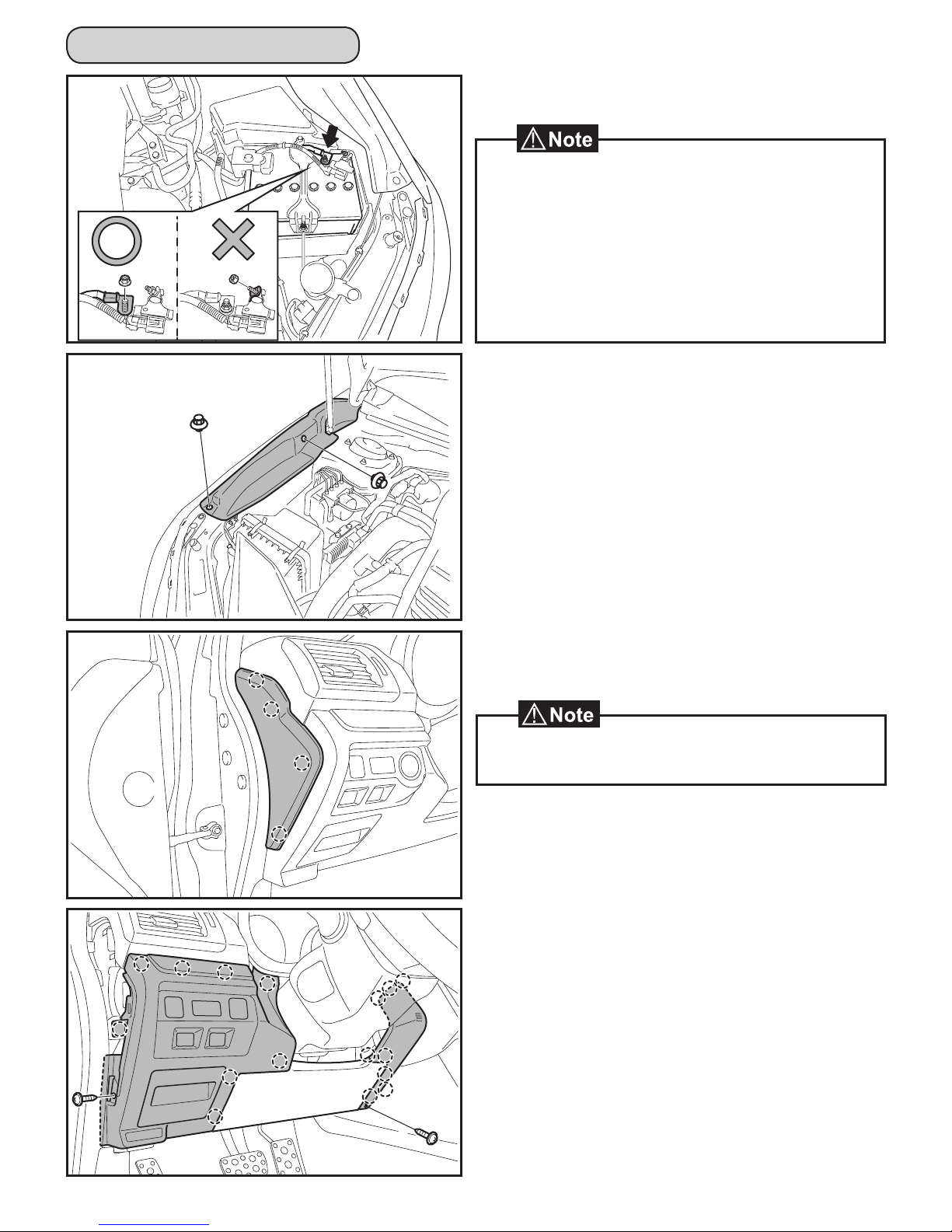
2. Disconnect the Negative Battery Terminal.
• Do not touch the Positive Battery Terminal with the
Negative Terminal.
• Note the Battery Cable Position as it will be reinstalled in
the same position.
• Wait at least 30 seconds after disconnecting the
Negative Battery Terminal before disconnecting the
Airbag Connector.
• After the work with battery disconnected, some vehicle
system should be reconfigured. See service manual.
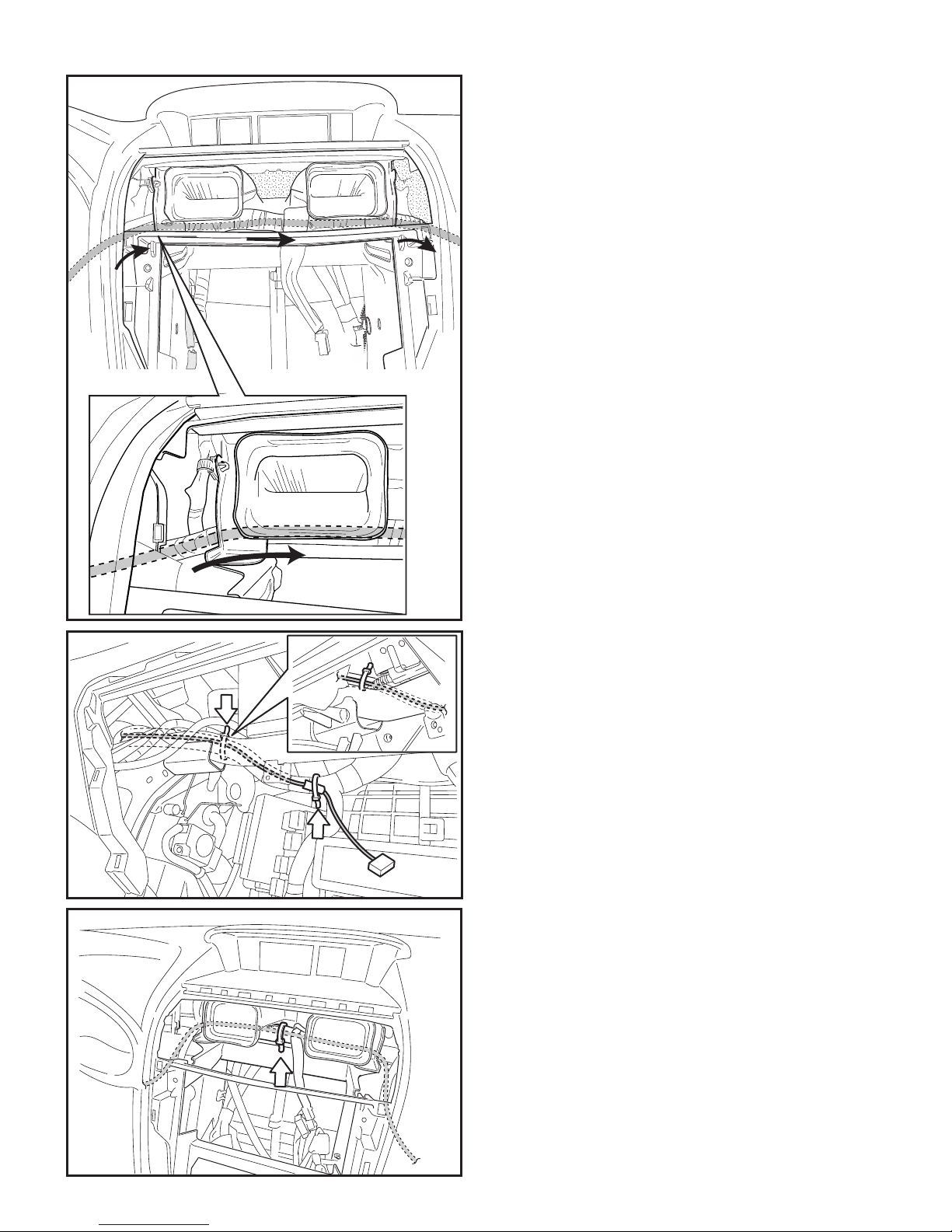
3. Remove the Passenger's Side Fender Cover.
• Remove 2 Clips.
4. Remove the Driver’s Side Dash Cover.
• Disengage 4 Clips.
• Disengage and remove cover from the bottom first
and work upward.
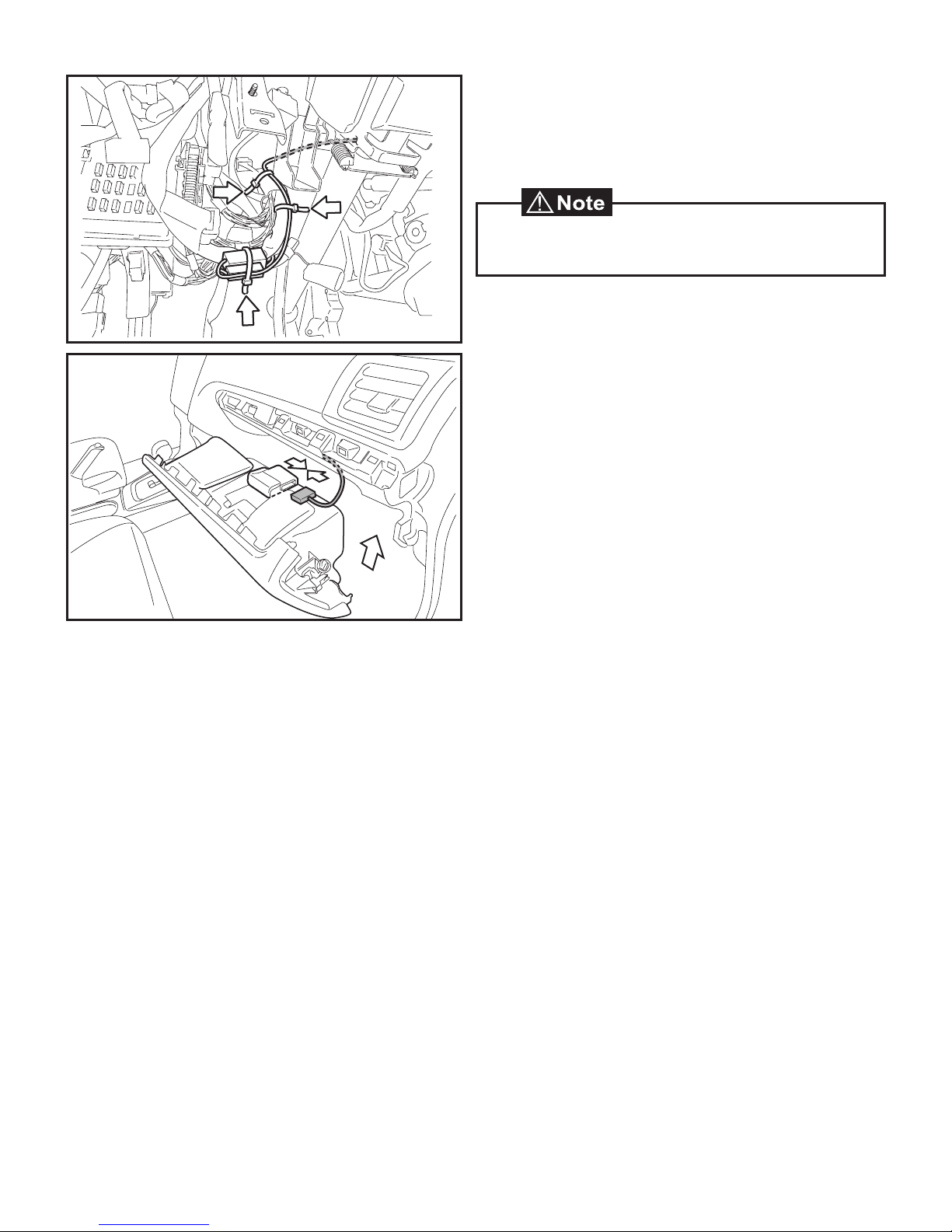
5. Remove the Lower Dash Cover No.1.
• Remove 1 Screw.
• Disengage 8 Clips.
• Disconnect Vehicle connectors.
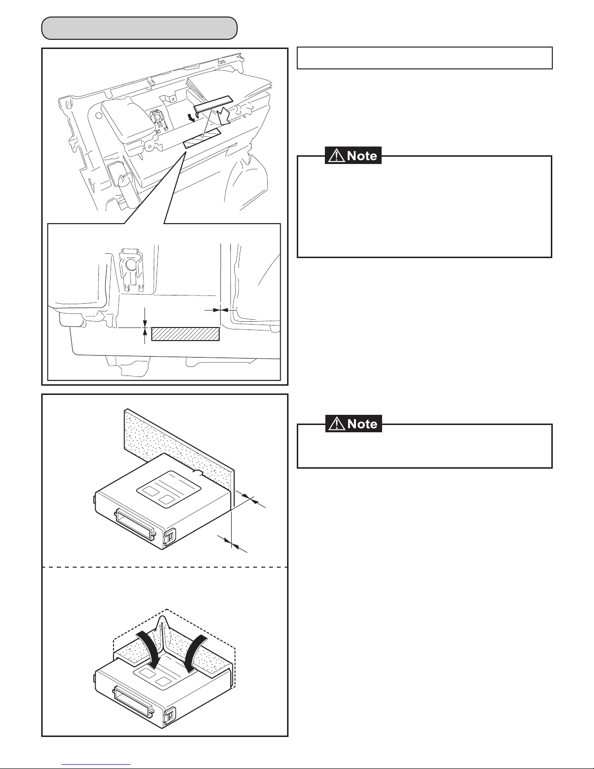
6. Remove the Lower Dash Cover No.2.
• Remove 1 Screw.
• Disengage 8 Clips by pulling both the top and
bottom of the panel simultaneously.
- 3 -

10. Remove the Passenger’s Side Dash Cover.
• Disengage 4 Clips.
9. Remove the Audio Unit.
• Remove 6 Screws.
• Disconnect Vehicle connectors.
8. Remove the Center Cluster Panel.
• Disengage 13 Clips.
• Disconnect Vehicle connectors.
7. Remove the Driver’s Side Knee Airbag carefully.
• Remove 2 Nuts.
• Hold Airbag as to prevent tension on the Harness.
• Disengage the Yellow Connector Lock by using a
pick tool to lift upward.
• Use a Panel removal tool to carefully lift upward to
unplug the Airbag Connector.
• Wait at least 30 seconds after disconnecting the
Negative Battery Terminal before disconnecting the
Airbag Connector.
• Disengage and remove cover from the bottom first
and work upward.
• Disengage and remove cover from the bottom first
and work upward.
- 4 -

11. Remove the Ornament Panel.
• Disengage 6 Clips.
12. Open the Glove Box.
13. Dislodge the Glove Box.
15. Remove the Lamp Pocket Cover.
• Disengage 1 Clip.
16. Remove the Pocket Lamp from Lamp Pocket Cover.
• Disconnect Vehicle connectors.
17. Remove the Glove Box Inner Cover.
• Remove 7 Screws.
• Disengage 7 Clips.
• Disengage 2 vehicle harness Clips.
14. Remove the Under Cover.
• Remove 3 Clips.
- 5 -

Installation Procedure
SES ECU Preparation and Installation
1. Clean the area indicated on the topside of the Glove
Box Inner Cover.
2. Attach the Double-Sided tape to the Glove Box
Inner Cover as shown.
• Clean attachment surface using isopropyl alcohol and
cleaning towel.
• To achieve maximum bond strength of Tape, the
attachment surface temperature must be between
68°F-110°F (20°C-43°C) upon application.
• Verify that the Double-sided tape is firmly attached.
3. Attach the Foam Tape to the SES ECU as shown.
0mm
0mm
• Clean attachment surface using isopropyl alcohol and
cleaning towel.
OO
OO
- 6 -

4. Attach the SES ECU to the topside of the Glove Box
Inner Cover as shown.
• Clean attachment surface using isopropyl alcohol and
cleaning towel.
• To achieve maximum bond strength of Tape, the
attachment surface temperature must be between
68°F-110°F (20°C-43°C) upon application.
• Verify that the SES ECU is firmly attached.
1. Route the Main Harness's 24P Connector toward
the Glove Box area.
2. Route the Main Harness's 8P and 2P Connectors
toward the J/B area.
Main Harness Installation
• Use caution when installing the Main Harness. Be
sure to route and attach harness away from sharp
metal surfaces.
OO
OO
- 7 -

3. Route the Main Harness's 24P Connector along the
Vehicle Harness behind the Vehicle Bracket.
4. Route the Main Harness's 24P Connector toward
the Glove Box area.
5. Secure the Main Harness White Marker to the
Vehicle Harness using 1 Tie Wrap.
6. Secure the Main Harness to the Vehicle Harness
using 1 Tie Wrap.
7. Secure the Main Harness to the Vehicle Harness
using 1 Tie Wrap.
- 8 -

8. Secure the Main Harness to the Vehicle Harness
using 1 Tie Wrap.
9. Remove the Tape securing the Vehicle’s 8P and 2P
Pre-Connectors.
10. Disconnect the Wire Jumper connector from the
Vehicle's 2P Pre-Connector.
11. Connect the Main Harness's 8P Connector to the
Vehicle's 8P Pre-Connector.
12. Connect the Main Harness's 2P Connector to the
Vehicle's 2P Pre-Connector.
• Discard the Wire Jumper connector. (This is used for
the power window interrupt circuit.)
• Ensure routing of main harness does not interfere
with climate control mechanism. The main harness
must be secured to the vehicle harness with no slack
in this area.
- 9 -

13. Secure the Main Harness to the Vehicle Harness
using 2 Tie Wraps.
14. Secure the 8P and 2P Connector to the Vehicle
Harness using 1 Tie Wrap.
15. Connect the Main Harness’s 24P White Connector
to the SES ECU.
16. Reinstall the Glove Box Inner Cover.
FM5-RES052
• The Smart Engine Start ID must be registered first, so
do not secure the 1P Connectors yet.
- 10 -

Vehicles Without Relay Box
1. Remove and discard the Bolt Hole Seal.
2. Attach the Bolt (M8x20) and Semi-tighten as shown.
Hood Switch Installation and Wiring Procedure
Y
H
J
I
Vehicles With Relay Box
3. Loosen the Vehicle Bolt.
Y Hood Switch
H 2P Gray
I 2P Black
J 2P Gray
- 11 -

4. Attach the Switch Bracket to the Switch Holder with
the Black Bolt (M6×16) and the Nut as shown.
Nut Side
Bolt Side
• Tighten the Nut to 5.6 N·m (0.57 kgf·m, 4.13 ft-lb)
- 12 -

6. Attach the Hood Switch to the Hood Switch Holder
with the Screw.
• Tighten the Screw to 2.6 N·m (0.27 kgf·m, 1.92 ft-lb)
5. Attach 1 Foam Tape to the Hood Switch as shown.
• Make sure the Guide Pin is seated correctly and verify
that the Screw is tightened securely.
• When Attaching the Hood Switch Holder to the Hood
Switch, Do not hold the NG Area of the Hood Switch.
NGArea
OKArea
- 13 -

7. Attach the hook of the Hood Switch Bracket to the
Vehicle's stud bolt as shown.
• Insert the Hood Switch Bracket in between the Vehicle
body and the Vehicle bracket.
8. Make sure the bracket is seated on the Bolt
correctly.
9. Secure the Hood Switch to the Vehicle with the
Bolt (M8×20).
• Tighten the Bolt to 33 N·m (3.4 kgf·m, 24 ft-lb)
T
10. Connect a circuit tester (ohm meter, continuity
meter, etc.) to the Hood Switch 2P Connector.
- 14 -

If there is continuity with the hood closed:
13. Remove the Hood Switch Assembly.
14. Remove the Switch Holder and Hood Switch From
Switch Bracket.
15. Attach the Switch Bracket to the Switch Holder with
the Bolt (M6×16) and the Nut as shown.
16. Pull out the Vehicle’s 2P Pre-Connector which is at
the back of the Air Cleaner Box cover.
17. Disconnect the Dummy Connector from the
Vehicle's 2P Pre-Connector.
• Discard the Dummy Connector.
11. Close the Hood.
12. Check the continuity of the Hood Switch using the
Circuit Tester.
• Hood open : Continuity (closed circuit)
• Hood closed : No Continuity (open circuit)
→Gotostep16
Continuity (closed cirtcuit)
→Gotostep13
- 15 -

18. Connect the Hood Switch 2P Connector to the
Sub-Harness 2P Connector.
20. Route the Hood Switch Harness's 2P Connector
toward the Air Cleaner Box area.
1 2
3 4
19. Attach 4 pieces of Foam Tape to the Hood Switch
2P Connectors as shown.
- 16 -

25. Reinstall the Passenger's Side Fender Cover.
24. Secure the Sub-Harness to the Vehicle Body
using a Harness Clamp.
21. Attach 1 piece of Foam Tape to the Vehicle's
2P Pre-Connector.
22. Attach 1 piece of Foam Tape to the Sub-Harness
2P Connector.
23. Connect the Sub-Harness 2P Connector to the
Vehicle's 2P Pre-Connector.
0mm 0mm
- 17 -

26. Secure the Sub-Harness and connectors to the
Vehicle Harness using 2 Tie Wraps.
• Route the Sub-harness so that it is clear from the
opening range of the Air Cleaner Box cover.
27. Finish reassembling the Vehicle.
• Verify that panels fit together properly, with no
uneven gaps.
• Verify that all Connectors are plugged in.
ALREADY INSTALLED
• Tighten the Knee Airbag Nuts to 7.5 N·m
(0.8 kgf·m, 5.5 ft-lb)
- 18 -

Registration Procedure
3. With foot off the brake pedal, Press the "ENGINE
START STOP" button twice to switch the ignition on.
4. Remove the Tape securing the Main Harness’s 1P
SES Diagnostic Connectors.
1. Open the Hood and leave it open throughout the
registration procedure.
• Doors can remain open during registration.
2. Temporarily reconnect the Negative Battery Cable.
5. Connect the 1P SES Diagnostic Connectors.
6. Register the SES ECU using the procedure on
the next page.
• Do not touch the Positive Battery Terminal with the
Negative Battery Terminal.
- 19 -

SYSTEM REGISTRATION for SDI
For registration by DST-i SSM, reference immobilizer registration Manual.
SDI SETUP
REGISTRATION SETUP
Press and hold the SDI “Menu” and “C” buttons simultaneously
for approximately 5 seconds to enter stand alone mode.
Plug the SDI
diagnostic plug into
the vehicle's
diagnostic
connector.
Proceed to
“Registration
Setup”
Using the arrows on
the SDI select:
“SUBARU Vehicle”
Using the arrows on
the SDI select:
“All other model”
Using the arrows on
the SDI select:
“IMM Regist”
The SDI screen will
display:
"Select Reg Sys"
Press Enter to select
"Immobi Sys: ENT"
ENTERENTER ENTER
ENTER
The SDI screen will
display:
"Smart system: ENT
Otherwise: C"
The SDI screen will
display:
"IMMOBILIZER"
Using the arrows on
the SDI select:
"R/C E/G ST Reg"
The SDI screen will display:
"Execute regist.
Remo.con.eng.st
YES: ENT/NO:C"
ENTER
ENTER
ENTER
The SDI screen will
display:
"Remo.con.eng.st
regist.success"
The SDI screen will
display:
"Initializing
communication..."
Registration
Complete.
- 20 -
Table of contents
Languages:
Other Subaru Remote Starter manuals

Subaru
Subaru LEGACY H7110LS200 User manual

Subaru
Subaru H011SAJ400 User manual

Subaru
Subaru H7110FS101 User manual

Subaru
Subaru H001SFJ800 User manual

Subaru
Subaru H001SXA000 User manual

Subaru
Subaru Remote Start User manual

Subaru
Subaru H001SFJ600 User manual

Subaru
Subaru H001SSG400 User manual

Subaru
Subaru H001SFL400 User manual

Subaru
Subaru H001SFL300 User manual
Popular Remote Starter manuals by other brands

Brickhouse Security
Brickhouse Security JumpStart Solo user guide

Audiovox
Audiovox AA-RS20CS installation instructions

Kings Adventure
Kings Adventure AKEP-LJS1000A_01 user manual

Voxx Electronics
Voxx Electronics Elite Series owner's guide

CrimeStopper
CrimeStopper PS01-G5 operating instructions

ADS
ADS iDatastart HC1151A Product guide