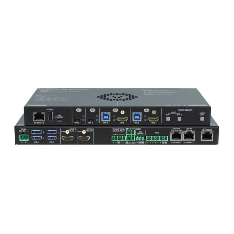
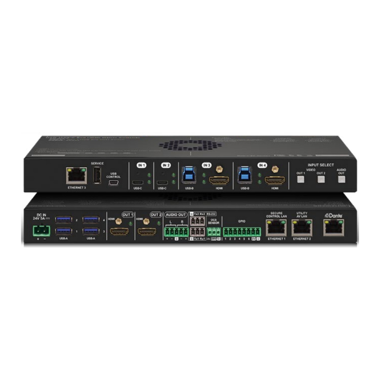
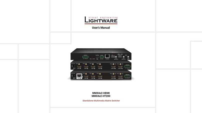
Lightware MMX8x8-HDMI-4K-A User manual

MMX8x4-HT420M
MMX8x4-HT400MC
MMX8x8-HDMI-4K-A
User’s Manual
Multiport Matrix Switcher

MMX8x4-HT series – User's Manual 2
Important Safety Instructions
Class I apparatus construction.
This equipment must be used with a mains power system with a
protective earth connection. The third (earth) pin is a safety feature,
do not bypass or disable it. The equipment should be operated only
from the power source indicated on the product.
To disconnect the equipment safely from power, remove the power
cord from the rear of the equipment, or from the power source. The
MAINS plug is used as the disconnect device, the disconnect device
shall remain readily operable.
There are no user-serviceable parts inside of the unit. Removal of the
cover will expose dangerous voltages. To avoid personal injury, do not
remove the cover. Do not operate the unit without the cover installed.
The appliance must be safely connected to multimedia systems.
Follow instructions described in this manual.
Ventilation
For the correct ventilation and to avoid overheating ensure enough
free space around the appliance. Do not cover the appliance, let the
ventilation holes free and never block or bypass the ventilators (if any).
WARNING
To prevent injury, the apparatus is recommended to securely attach to
The apparatus shall not be exposed to dripping or splashing and that
be placed on the apparatus.
CAUTION AVIS
RISK OF ELECTRIC SHOCK
DO NOT OPEN
RISQUE DE CHOC ELECTRIQUE
NE PAS OUVRIR
Waste Electrical & Electronic Equipment
WEEE
This marking shown on the product or its literature,
indicates that it should not be disposed with other
household wastes at the end of its working life. To
prevent possible harm to the environment or human
health from uncontrolled waste disposal, please
separate this from other types of wastes and recycle it
responsibly to promote the sustainable reuse of material
resources. Household users should contact either the
retailer where they purchased this product, or their local government
environmentally safe recycling. Business users should contact their
supplier and check the terms and conditions of the purchase contract.
This product should not be mixed with other commercial wastes for
disposal.
Common Safety Symbols
Symbol Description
Alternating current
Protective conductor terminal
Caution, possibility of eletric shock
Caution

MMX8x4-HT series – User's Manual 3
Symbol Legend
The following symbols and markings are used in the document:
WARNING! Safety-related information which is highly
recommended to read and keep in every case!
ATTENTION! Useful information to perform a successful procedure;
it is recommended to read.
INFO: A notice which may contain additional information. Procedure
can be successful without reading it.
DEFINITION: The short description of a feature or a function.
TIPS AND TRICKS: Ideas which you may have not known yet but can
be useful.
Navigation Buttons
Go back to the previous page. If you clicked on a link previously,
you can go back to the source page by clicking the button.
Navigate to the Table of Contents.
Step back one page.
Step forward to the next page.
Document Information
Allpresentedfunctionsrefertothe indicated products.Thedescriptions
have been made during testing these functions in accordance with the
Item Version
Lightware Device Controller (LDC) software 1.22.0b1
Lightware Device Updater Software 1.5.2
Controller rmware 1.0.0
Hardware 1.0
Document revision: 1.0
Release date: 27-04-2018
Editor: Judit Barsony

MMX8x4-HT series – User's Manual 4
1. INTRODUCTION...................................................................................7
..............................................................................7
...................................................................................7
.......................................................................8
.....................................................................8
......................................................................9
.................................................................9
2. INSTALLATION...................................................................................10
......................10
.......................................................................11
....................12
3. PRODUCT OVERVIEW ......................................................................13
..................................................................................13
....................................................................................14
.............................................................15
....................................................... 15
....................................................................... 15
................................................................................ 15
........................................................................... 15
........................................................... 15
.............................................................................. 15
................................. 16
................................................................................ 16
...................................................................... 16
.................................... 16
............................................................... 16
..................................................17
.............................................................................17
...................................................................... 17
............................................................ 18
..........................................................................19
............................................ 19
.............................................. 19
........................................... 19
.................................................................. 20
..........................................................................20
......................................................................21
........................................................................... 21
................................................................................. 22
................................................................................ 23
................................................................................ 24
................................................................................ 25
..................................................................... 25
4. OPERATION .......................................................................................26
...............................................................................26
................................................................................26
............................................26
................................................................... 27
..................................................................................... 27
..................................................................................... 28
.................................................................................... 28
............................................................................ 29
................................................29
................................................................................... 29
.................................................................. 29
.................................................................... 29
..................................................................... 30
..................................................................................... 30
.................................................................................... 31
.................................................................... 31
................................32
...................................................................................... 32
............................................................................... 32
5. SOFTWARE CONTROL – LIGHTWARE DEVICE CONTROLLER ...33
..................................................................33
.........................................................................33
...........................................................34
........................................................................35
................................................................... 36
....................................................................................36
.............................................................. 36
............................................................................... 36
........................................................... 37
.......................................... 38
.. 38
....................................................................................39
............................................................. 40
........................................... 40
................................................... 41
.............................................. 41
....................... 41
................................................ 42
............................... 42
................................................................................43
...................................................................................44
.............................................................. 44
.............................................................................. 44
................................................................. 45
............................................................................... 45
............................................................................. 46
............................................................................46
...................................................................................... 46
........................................................................................... 47
........................................................................................... 47
......................................................................................... 48
......................................................................................... 48
.........................................................................49
............................................................................ 49
............................................................ 50
.................................................... 50
.......................................................... 51
............................................................ 51
..........................................................................51
............................................................................................ 51
.................................................................................. 52
.......................................................................................... 52
.......................................................................................... 52
.......................................52
.......................................................... 52
................................... 53
.................................. 53
............. 53
..........................................................................54
Table of Contents

MMX8x4-HT series – User's Manual 5
6. LW2 PROGRAMMERS’ REFERENCE ...............................................55
.........................................................55
.............................................................55
.......................................................................... 55
....................................................................... 55
.......................................................................... 56
................................................................... 56
............................................... 56
.............................................................................. 56
.................................................................................. 56
.................................................................. 56
................................................. 56
............................................................. 56
..................................................................... 57
................................................. 57
..................................................57
.................................................... 57
....................................................... 57
................................................................... 57
............................................................... 57
.............................................................................. 57
........................................................................... 57
........................................... 58
...................................................................... 58
..............................................................58
.............................................................58
........................................................... 58
..............................................................58
..................................................................59
...........................................................59
...............................................................59
....................................................59
........................................................59
...........................................................59
.............................................................................59
............................................................................ 59
................................................................................ 59
...........................................................................60
....................................................... 60
............................................................ 60
..............................................60
7. LW3 PROGRAMMERS' REFERENCE...............................................61
.....................................................................................61
...............................................61
................................................................................................ 61
........................................................................................... 62
............................................................................................ 62
...............................................................63
.......................................................................................... 63
............................................................................... 63
.............................................................................. 63
..........................................................63
...........................................................................64
................................................................................. 64
................................................................................. 65
....................................................................................... 65
............................................................................................ 66
......................................................................................... 66
.................................................................................... 66
..................... 67
.....................................................................67
......................................................................68
................................................................ 68
................................................................... 68
....................................................................... 68
................................................................ 68
....................................................................... 68
............................................ 68
..........................................69
................................................. 69
.................................................... 69
.................................................. 69
...................................................................69
.......................................................................... 69
..................................................................... 69
....................................................................... 69
.................................................................. 69
.......................................................................... 70
....................................................................... 70
....................................................................... 70
.................................................................... 70
.................................................... 70
.......................................... 71
............................................................ 71
......................................................... 71
.......................................... 72
...................................................... 72
........................................................ 72
.................................................. 73
................................................ 73
.................................................................................... 73
............................................ 73
.................................................................................. 74
.....................................................................74
........................................................... 74
................................................................. 75
................................................... 75
.......................................75
...................................................................... 75
................................................ 75
............................................. 76
.........................................................77
.......................................................... 77
..................................................... 79
.................................................. 80
.................................................. 83
................................................................84
............................................................................ 84
........................................................................ 84
............................................................... 85
................. 85
.......................................................................85
......................................................................... 85
.......................... 85
.................................................................85
....................................................... 85
..................................................................86
.................................................... 86
.............................................. 86
.................................................... 86
...........................................................86
...................................................... 86
................................................... 86
............................................................ 86
................................................................ 86
............................................... 87
........................................ 87
................................................................ 87
MMX8x4-HT series – User's Manual 6
.....................87
................................................... 87
................................................... 87
......................................... 88
................................................89
...................................................... 89
............................................ 89
............................................................... 89
.............................................................................. 89
................................................................. 89
......................................................................................... 90
8. FIRMWARE UPGRADE ......................................................................95
.....................................95
....................................................................95
..................................................................95
................................................................96
96
.................................... 96
.........................................99
9. TROUBLESHOOTING......................................................................100
....................100
10. TECHNOLOGIES............................................................................101
...................................................................101
............................................................. 101
.................................................... 101
.................................................................102
.........................................102
............................................... 102
...................................................103
11. APPENDIX ......................................................................................104
..........................................................................104
............................................................105
...............................................105
......................................................106
..........................................................107
......................................................................108
................................................................... 108
................................................................. 108
..................................................................... 109
...................................................................110
.......................................................111
..............................................................112

1. Introduction MMX8x4-HT series – User's Manual 7
In MMX8x4-HT400MC and MMX8x4-HT420M models the special
Audio Input Block includes input ports for microphone and line-in. The
built-in sound mixer DSP allows for free mixing of the audio signals
from the de-embedded HDMI, the microphone or the line-in. The MIC
port can also supplies phantom power to the connected microphone.
the speaker to become automatically focused, and the volume of
the rest of the sounds to be lowered, as soon as the presenter starts
speaking. The built-in DSP provides audio mixer services including
MMX8x8-HDMI-4K-A has six balanced, 5-pole Phoenix audio inputs or
outputs for embedding or de-embedding purposes.
The unit can be controlled via RS-232, Ethernet or USB ports, but it also
offers RS-232, Serial and IR command injection capabilities allowing
to send any control command directly to end points.
Model Denomination
MMX8x4-HT400MC
8 inputs
Multimedia matrix
HDMI and TPS (HDBaseTTM) interfaces
MMX8x4-HT420M
Multimedia matrix
MMX8x8-HDMI-4K-A
4x HDMI
outputs
Mic addon
Corporate
4x TPS inputs, 0x TPS outputs
8 inputs
4x HDMI
outputs
HDMI and TPS (HDBaseTTM) interfaces
Mic addon
4x TPS inputs, 2x TPS outputs
8 inputs HDMI interfaces Audio
8x HDMI outputs
Multimedia matrix Transmits 4K video signal
1
Introduction
chapter we would like to introduce the device highlighting the most important
features in the below listed sections:
Ý
Ý
Ý
Ý
Ý
Ý
Description
for collaboration room environments. It has eight video inputs and
supported.
Infrared emitter unit
Phoenix Combicon
2-pole connector
Phoenix Combicon
3-pole connector 1
Matrix Unit IEC Power Connector
Infrared emitter unit
with Jack connector1
cable, CAT5e type,
0.25m length (2x) 2
Phoenix Combicon
2-pole connector (4x) 2
Phoenix Combicon
5-pole connector 1
Phoenix Combicon
8-pole connector 2
Safety and
Warranty
Info
Quick
Start
Guide
1
2 Only for the MMX8x4-HT420M model.
CAT5e type, 3m length

1. Introduction MMX8x4-HT series – User's Manual 8
Model Comparison
Model
A/V INPUTS A/V OUTPUTS Interface ports
HDMI input
TPS input
Analog audio in
Microphone in
HDMI output
TPS output
Analog audio out
Ethernet
IR TX
IR/ TTL Serial TX
RS-232 Serial
Relay
GPIO
USB
MMX8x4-HT400MC 4x 4x 1x 1x 4x - 1x 1x 2x 2x 2x - - 1x
MMX8x4-HT420M 4x 4x33x11x 2x 2x33x17x 4x 2x 2x 4x 6x 1x
MMX8x8-HDMI-4K-A 8x - 6x2- 8x - 6x21x 2x 2x 2x - - 1x
1
2
3 PoE-compliant port.
Typical Application
Madein EU, Hungary
50/60Hz 1.4-0.85A
100-240VAC
Sn:
Reset
3
4
RXTXRX TX
2 1
TXTX
4RS232
2 1
3
MICIN
AUDIOOUT
AUDIOIN
TPS+PoEIN1 TPS+PoEIN2 TPS+PoEIN3
IROUT
TPS+PoEIN4
ETHERNET
AUDIO1IN
VIDEO AUDIO
INPUTSTATUS
RESET
Audio1
HDMI
DP
DVI-D
HDCP
Autoselect
DVI-AVideo
Audio2
VGA
HDMI
DP
DVI-D
3DPIN
2
VIDEO
SELECT
AUDIO
SELECT
SHOW
ME
WP-UMX-TPS-TX130-US
VIDEO
SELECT
ETHERNET
INPUTSTATUS
VIDEO AUDIO
O
RESET
IR
VGA
DP
HDMI
Autoselect
AUDIO
SELECT
SHOW
ME
2DPIN 3
AUDIO
DP
HDMI
TPSLink
HDMI OUT1 HDMI OUT2
ON
OFF
MacBook
Laptop
Laptop Mic
Projector
PC
Speakers
Monitor
Monitor
UMX-TPS-TX140
MMx8x4-HT400MC
CATx
DisplayPort
RS-232
HDMI
Analog audio
LAN
IR
WP-UMX-TPS
-TX130-US
Power
amplifier
HDMI
HDMI
HDMI
HDMI
HDMI
HDMI
LAN
IR
IR emitter
Analog
audio
Mic
audio
CATx
CATx
DP
Analog
audio
Analog
audio
Madein EU, Hungary
50/60Hz 1.4-0.85A
100-240VAC
Sn:
Reset
3
4
RXTX RX TX
2 1
TXTX
4RS232
2 1
3
AUDIOI/O
HDMI OUT1 HDMI OUT2 HDMI OUT3 HDMI OUT4
HDMI OUT5 HDMI OUT6 HDMI OUT7 HDMI OUT8
HDMI IN1 HDMI IN2 HDMI IN3 HDMI IN4 HDMI IN 5 HDMI IN6 HDMI IN7 HDMI IN8
AUDIOI/O
AUDIOI/O AUDIOI/O AUDIOI/O
AUDIOI/O
IROUT
ETHERNET
Media player
Projector
PC
Laptop
Speakers
Power
amplifier
MMX8x8-HDMI-4K-A
TPS
HDMI
Analog audio
LAN
RS-232
Sn:
MadeinEU, Hungary
RoHS
Ethernet10/100
BidirectionalIR
BidirectionalRS-232
TTPPSSLLoonngg DDiissttaannccee TTrraannssmmiitttteerr
HDMI,3D, 4K supported
Forbest performance useAWG23 CAT6or CAT7 SFTP cable
PIN:2mm
12V1ADC
HDMI--TPS--TX97
Devicecan be remote powered over TPS link with PoE
(IEEE802.3af)
TPSOUTPoE
( )
TPS
(up to 170 m)
12VDC
1.5A---
_
PIN:2mm
12VDC
1.5A---
_
AUDIOOUT
HDMIOUT
SIGNAL AUDIO
TPSIN(PoE)
TPSReceiver with Relay modules and Audio de-embedding
HHDDMMII--TTPPSS --RRXX111100AAYY
MadeinEU, Hungary
RoHS
Forbestperformance use AWG23
CAT6orCAT7 SFTPcable
Devicecanbe remote powered over TPS link with PoE
(IEEE802.3af)
Sn:
FrontLEDs
LIVE
RS-232
Fastblinking(0.5 sec): Firmware upgrade mode
ON:Poweredbut no operation
OFF:Nopower
OFF:Pass-throughmode
Blinking(1sec): Normal operation
Blinking:CommandInjection mode
ON:Controlmode
OFF:NoTPS link
TPSLINK
Blinking:Lowpower mode
ON:TPSlink active
AUDIOOUT
OFF:Embeddedaudio not present or muted
Blinking:Embeddedaudio format not supported
foraudiode-emebedding
ON:Embeddedaudio present and de-embedded
HDCP
Blinking:NonHDCP capable device connected,
encryptedsignalreplaced with red screen
RearLEDs
SIGNAL
ON:Signalpresent
OFF:Outputsignal not present or muted
TPSINPUT
HDMIOUTPUT
OFF:Outputsignal notHDCPencrypted
ON:Outputsignal HDCPencrypted
-Remotepower (PoE)
-TPSLink
Power
amplifier
Speakers
Monitor
HDMI-TPS-RX110AY
1 2 3 4 5 6 7 8
PUSHTO EJEC T
CD/ USB / S D / AUX / BT / FM / AM
EJECT
SD
TEXT
LOCK
ALL/
FOLDER
RANDOM
REPEAT
AUXIN
POWER
USB
CD/USB/SD
AUX/BT
STOP PLAY
BT AAC
2 00:03:16
HDMI-TPS-TX97
Huddle room 1.
Huddle room 2.
Server room
RS-232
HDMI
HDMI Analog
audio
Analog audio
Analog audio
HDMI
HDMI
HDMI
LAN

1. Introduction MMX8x4-HT series – User's Manual 9
Compatible Devices
matrix boards third-party HDBaseTTM extenders, displays, but not
compatible with the phased out TPS-90 extenders.
removed or set to 'Remote power disabled' position.
4:4:4 colorspace.
Relevant inputs and outputs are fully HDCP compliant.
HDCP capability on the HDMI inputs can be disabled
when non-protected content is extended.
Advanced EDID Management
The user can emulate any EDID on the inputs
independently, read out and store any attached
monitor's EDID in internal memory locations, upload
Controller software.
Each output has a clean, jitter free signal, eliminating
signal instability and distortion caused by long cables
The exact video and audio signal format can be
determined such as timing, frequencies, scan mode,
HDCP encryption, color range, color space and audio
sample rate.
LCD
Easy setting and menu navigation are assured by the
color graphic display and the comfortable jog dial
control.
Event Manager
The Event Manager tool takes care of all the necessary
changes. Hence, in a less complex environment, there
is no need to invest in additional control solutions,
which makes the matrix the best choice for numerous
applications.
mute, balance and gain.
The analog audio can be embedded to HDMI outputs
and embedded audio can be routed to the analog audio
output.
Advanced Audio
applications. The matrix switcher support direct analog
audio connections to ease system integration. Analog
audio ports feature volume and gain controls. These
controls help to interface with an audio subsystem or
if the ports are connected directly to audio sources or
speakers they provide easy sound adjustment.
Special Audio Input Block for Microphone and Line-in
Special Audio Input block with input ports for
microphone and line-in. The built-in sound mixer allows
for free mixing of the microphone, the line-in and the
de-embedded audio.
Infra
Infrared (IR) is a wireless technology used for device
communication over short ranges. Third party control
systems may send IR control commands to endpoints
turning them on and off or switching their inputs.
Relay
The MMX8x4-HT420M matrix is PoE-compatible.
system which pass electric power along with data on
twisted pair Ethernet (CAT) cabling. This allows a single
cable to provide both data connection and electric power
to remote devices.

2. Installation MMX8x4-HT series – User's Manual 10
2
Installation
The chapter is about the installation of the device and connecting to other
:
Ý
Ý
Ý
Mounting Options -Standard Rack Installation
The matrix can be mounted in several ways by the supplied two rack
ATTENTION!
ears to the housing. A longer screw may touch internal parts.
and right side as shown in the picture. The default position allows
mounting the device as a standard rack unit installation.
Standard rack installation
ATTENTION!
Keep minimum two threads left after the nut screw.
Mounting the device to the rack rail
INFO: The matrix switcher is one rack wide and 2U high.
WARNING! Never block the ventilation holes on any side of the
Direction of the airow
min. 2
threads left
rack rail
rack shelf mounting ear
rack screw
flat washer
cage nut

2. Installation MMX8x4-HT series – User's Manual 11
Connecting Steps
CATx
Connect an HDBase-TTM -compatible transmitter or matrix output board to TPS input port.
MMX8x4-HT400MC model is not PoE-compliant,andMMX8x4-HT420M model is PoE compliant.
HDMI
Connect an HDMI source (e.g. PC) to the HDMI input port.
HDMI
Connect an HDMI sink (e.g projector) to the HDMI output port.
Audio
output port by an audio cable.
Mic
Please read the Installation Guide for Connecting a Microphone section before connecting the
microphone to the matrix. Not proper setting could damage the device.
Audio
Optionally for audio input: connect the audio source (e.g. media player) to the audio input port
by an audio cable.
USB
Controller software.
LAN
Optionally connect the UTP cable (straight or cross, both are supported) in order to control the
Relay
Optionally for relays: connect a controlled device(s) (e.g. a projection screen) to the relay port.*
IR
connector) to transmit infra signal.
GPIO
Power
Connect the power cord to the AC power socket to the matrix unit. It is recommended to power
*Only in MMX8x4-HT420M model.
USB
Control
POWER
LIVE
Multiport HDMI and TPS Matrix Switcher
MMX8x4-HT420M
MAIN MENU
>System Settings
InputPor ts
OutputPor ts
Projection screen
RS-232
HDMI
RS-232
Power
outlet
TPS transmitter
device
Laptop
PC Projector
Infra emitter
Audio Amplifier Microphone
Media Player
HDMI
IR
CATx
LAN
Power
USB
Audio
Audio
TPS receiver
device
Mic HDMI
Relay GPIO
Button panel
MMX8x4-HT420M
CATx
+48
+36
+24
+15
+10
+6
+48
+36
+24
+15
+10
+6
USB
Control
POWER
LIVE
MAIN MENU
> System Settings
Ports
EDID
Health LOCK
OUTPUT
CONTROL
LOCK
SAVE
PRESET
LOAD
PRESET
TAKE
AUTO
MX8x8-HDMI-4K-A
Multiport HDMI Matrix Switcher
1 2 3 4 5 6 7 8
1 2 3 4 5 6 7 8
CCOONNTTRROOLL
LLOOCCKK
LLOOCCKK
OOUUTTPPUUTT
TTAAKKEE
AAUUTTOO
TTAAKKEE
AAUUTTOO
LLOOAADD
PPRREESSEETT
LLOOAADD
PPRREESSEETT
SSAAVVEE
PPRREESSEETT
SSAAVVEE
PPRREESSEETT
Power outlet
Laptop
PC Projector
Infra emitter
Media Player
Audio Amplifier
+48
+36
+24
+15
+10
+6
+48
+36
+24
+15
+10
+6
HDMI Audio
Power LAN
USB
IR Audio
MMX8x8-HDMI-4K-A

2. Installation MMX8x4-HT series – User's Manual 12
Installation Guide for Connecting a Microphone
The device features a dedicated Special Audio Input Block for microphone. Before connecting a microphone
to the matrix device please read the instructions below.
These settings can be done from a computer using the
software. The application is available at www.lightware.com
Step 1. Always check the correct wiring of the microphone cable. See more details about the wiring in Audio Cable
section. Microphone cable should be shielded with 2x0,22mm conductor, max. 50m long.
Step 2. Before the connection, please set these properties below:
Value Lightware Device
Controller LW3 command
Advanced
audio output
or Mute
-80
-80
dB
MUTE ˃SET /MEDIA/AUDIO/O6.Volume=-80
˃SET /MEDIA/AUDIO/O6.Mute=true
Microphone
input
or Mute
-80
-80 dB
MUTE ˃SET /MEDIA/AUDIO/I9.Volume=-80
˃SET /MEDIA/AUDIO/I9.Mute=true
ATTENTION! Skipping the volume or mute setting can cause serious damage in the
speaker or the external sound system when phantom power is turned on!
Phantom
power Off +48V SET /MEDIA/AUDIO/I9.PhantomPower=false
ATTENTION! Always turn off the phantom power before connecting the microphone!
power is switched on.
Input gain -12dB -12
dB
GAIN
-12 +55
˃SET /MEDIA/AUDIO/I9.InputGain=-12
(High,Hmid,
00
-18
dB
+18
˃SET /MEDIA/AUDIO/I9.PEQ1Gain=0
˃SET /MEDIA/AUDIO/I9.PEQ2Gain=0
˃SET /MEDIA/AUDIO/I9.PEQ3Gain=0
˃SET /MEDIA/AUDIO/I9.PEQ4Gain=0
Panorama
(Balance) 00
PAN
LR
˃SET /MEDIA/AUDIO/I9.Balance=0
section.
Step 3. Connect the microphone.
a) In case of dynamic or wireless microphone: Skip this step and follow the instructions with Step 4.
b) In case of condenser microphone: Switch on the phantom power. Keep pressed the button
more than 2 seconds to activate phantom power.
Value Lightware Device
Controller LW3 command
Microphone
input
Phantom
power On +48V ˃SET /MEDIA/AUDIO/I9.PhantomPower=true
is necessary for normal operation of the condenser microphone. Application of the phantom power can
cause a damage if dynamic or wireless microphone is connected.
INFO: Always switch on the phantom power when the cabling and connecting have already done. Do not
disconnect the microphone when the phantom power is switched on!
Step 4. Set these properties below:
Value Lightware Device
Controller LW3 command
Advanced
audio output
0dB
0
dB
0
˃SET /MEDIA/AUDIO/O6.Volume=0
Microphone
input
0dB
0
dB
0
˃SET /MEDIA/AUDIO/I9.Volume=0
Step 5. Talk to the microphone continuously. Increase the microphone
input gain slowly and check the signal indicator chart. It gives a
feedback about the optimal signal level.
INFO: Take care that peak led (PK!) never lights up! See more details in
Signal indicator chart section.
Step 6. If the signal level is low, set the optimal volume both the microphone
input and balanced output channel. Always check the signal
indicator chart for the optimal level!
INFO: Take care that peak led (PK!) never lights up! See more details in
Signal indicator chart section.
+48V
MIC input gain MIC signal
-12 +55
PK!
NOM.
SIG.
MIC input volume Output volume
0
0

3. Product Overview MMX8x4-HT series – User's Manual 13
3
Product Overview
output ports and connectors:
Ý
Ý
Ý
Ý
Ý
Ý
Ý
Ý
INFO: Both the two models have the same look and controls on the front panel.
1
2 on
off The unit is powered off or internal voltage problem.
3LIVE LED blinking slow The unit is on and operates properly.
blinking fast The unit is in bootload mode.
4LCD Display
5 Easy setting and menu navigation by the jog dial control. Keep dial and click while
6Output Lock*
7Control Lock* Disable or enable front panel operations. Red light means the switching and
function buttons are disabled.
8Sources* Buttons to select an input, to select a preset number or to view the state of the
selected input port.
9Destinations* Buttons to select an output or to view the state of an output.
q
* Only in MMX8x8-HDMI-4K-A model.
USB
Control
POWER
LIVE
Multiport HDMI and TPS Matrix Switcher
MMX8x4-HT400MC
MAIN MENU
>System Settings
Input Ports
Output Ports
5
4
1
3
2
USB
Control
POWER
LIVE
MAIN MENU
> System Settings
Input Ports
Output Ports
LOCK
OUTPUT
CONTROL
LOCK
SAVE
PRESET
LOAD
PRESET
TAKE
AUTO
MX8x8-HDMI-4K-A
Multiport HDMI Matrix Switcher
1 2 3 4 5 6 7 8
1 2 3 4 5 6 7 8
CCOONNTTRROOLL
LLOOCCKK
LLOOCCKK
OOUUTTPPUUTT
TTAAKKEE
AAUUTTOO
TTAAKKEE
AAUUTTOO
LLOOAADD
PPRREESSEETT
LLOOAADD
PPRREESSEETT
SSAAVVEE
PPRREESSEETT
SSAAVVEE
PPRREESSEETT
5
4
1
3
2
76 8q
9

3. Product Overview MMX8x4-HT series – User's Manual 14
Rear View
Made in EU, Hungary
TPS IN 1 TPS IN 2 TPS IN 3 TPS IN 4
TPS LINK
50/60 Hz 1.4-0.85A
100-240 VAC
Sn:
3
4
IIRR OOUUTT 2 1
TXTX
4RS232
2 1
3
HDMI OUT 3 HDMI OUT 4
HDMI HDMI IN 6
IN 5 HDMI IN 7 HDMI IN 8
AUDIO OUT
AUDIO IN
L R
L R
48V
Reset
RXTX RX TX Control
ETHERNET
Boot
HDMI OUT 1 HDMI OUT 2
MIC IN
te
o567
9
8
w
4
32
1
Made in EU, Hungary
50/60 Hz 1.4-0.85A
100-240 VAC
Sn:
Reset
3
4
RXTX RX TX
2 1
TXTX
4RS232
2 1
3
MIC IN
AUDIO OUT
AUDIO IN
L R
65
IIRROOUUTT
t r ew
q
42 5 67
8
ui
yo
9
13
50/60 Hz 1.4-0.85A
100-240 VAC
Sn:
Made in EU, Hungary
Control
ETHERNET
Reset Boot
3
4
IIRR OOUUTT
RXTX RX TX
2 1
TXTX
4RS232
2 1
3
HDMI OUT 1 HDMI OUT 3
HDMI IN 1 HDMI IN 3
HDMI OUT 5
HDMI IN 5
HDMI OUT 6 HDMI OUT 7
HDMI IN 7
HDMI OUT 8
HDMI IN 2
HDMI OUT 2
HDMI IN 4
HDMI OUT 4
HDMI IN 6 HDMI IN 8
567
4
2
1
q
t
o
w
Rear View Legend
1
Infra output ports
3.5 mm Jack plugs for infra signal transmission (all of them are outputs).
2
output
ports
3
48 V LED
On
Off The phantom power is turned off.
4
RS-232 port
are also possible via RS-232 port. See more details in RS-232 Connector section.
5
Reset button
Reboots the matrix; the same as switching it off and on again.
6
Control Ethernet
port
See more details in Control Ethernet Port section.
7
Boot button
Hidden button for bootload mode (keep pressed the boot button and turn on the
matrix to take it bootload mode).
8
Advanced audio
input ports
3- pole Phoenix connector for microphone input and 5-pole Phoenix connector for
balanced analog audio input. See details about the audio features in Audio Interface
section.
9
Advanced audio
output port
5-pole Phoenix connector for balanced analog audio; the signal can be the
embedded audio from the TPS or HDMI inputs or from the microphone input or
from the line in. See details about the audio features in Audio Interface section.
q
outputs
5-pole Phoenix connector for balanced analog audio; depending on the
signal from the nearby HDMI port. See details about the audio features in
Audio Interface section.
w HDMI input ports for sources.
e
RJ45 connectors for incoming TPS signal.
▪MMX8x4-HT400MC and model is not PoE-compliant.
▪MMX8x4-HT420M model is PoE-compliant.
r
PoE-compliant. Pin assignment can be found in
Ports section.
t
AC connector
y RJ45 connectors for TPS signal; PoE-compliant.
u
Pin assignment can be found in the
iRelay 8-pole Phoenix connector for relay ports. Pin assignment can be found in the
Relay Connector section.
o HDMI output connectors for sinks.

3. Product Overview MMX8x4-HT series – User's Manual 15
Electrical Connections
The matrix switchers are assembled with standard
19-pole HDMI connectors with screw lock for inputs and
outputs. Always use high quality HDMI cable for connecting sources
and displays.
Analog Stereo Audio
5-pole Phoenix connector is used for balanced analog
audio input or output. Unbalanced audio signals
can be connected as well. See more details about
section.
Signal
1
2
3 Ground
4 Right-
5
Analog audio connector and plug pin assignments
Phoenix®
Microphone IN
INFO: MMX8x8-HDMI-4K-A model has no microphone input.
The 3-pole Phoenix connector is used for the analog microphone
Microphone connector and plug pin assignments
Phoenix®
1 2 3 4 5
Signal
1 Ground
2 -
3
1 2 3
section and about the connection in
Installation Guide for Connecting a Microphone section.
RS-232 Connector
The receiver contains a 3-pole Phoenix connector which is
used for RS-232 serial connection.
Signal
1 Ground
2 TX data
3 RX data
RS-232 connector pin assignments
RS-232 Output Voltage Levels
▪
▪
Phoenix®
Serial Interface section.
The matrix switcher contains a 2-pole Phoenix connector.
serial data output or Infra emitter.
Signal
1 Ground
2 TX data
Infra/ TTL serial connector pin assignments
▪
▪
In that case the actual current is:
▪
▪
1 2 3
21
Phoenix®
Serial Interface section
and about Infrared in the Infra Interface section.
IR Connector
IR emitter can be connected to the matrix switcher with TRS
(Tip, Ring, and Sleeve) connectors. They are also known as (3.5
mini-jack plug.
The pin assignments are the following :
1 2
1 Tip
2 Ring Signal (active low)
3 Sleeve
INFO: Ring pole of the emitter is optional. If your IR emitter has
three pole- TRS plug, then the Ring and the Sleeve are the same
signal (Output - ).
Infra Interface section.
Relay Connector
The MMX8x4-HT420M model contains a 8-pole
Phoenix connector which is used for relay
connection. The relays are potential free.
Signal
1 Pin 1 for Relay 1
2 Pin 2 for Relay 1
3 Pin 1 for Relay 2
4 Pin 2 for Relay 2
5 Pin 1 for Relay 1
6 Pin 2 for Relay 1
7 Pin 1 for Relay 1
8 Pin 2 for Relay 1
1 2 3 4
RELAY 1 RELAY 2 RELAY 3 RELAY 4
5 6 7 8
Relay connector pin assignment

3. Product Overview MMX8x4-HT series – User's Manual 16
Phoenix®
Relay Interface section.
MMX8x4-HT420M model contains a 8-pole
Phoenix connector with six GPIO pins, which
set to high or low level (Push-Pull). The direction of the pins can be input
Input voltage [V]
[mA]
Logical low level 0 - 0,8 30
Logical high level 2 - 5 18
INFO: The maximum total current for the seven GPIO pins is 180 mA.
Level and
direction
1
2
3
4
5
6
Ground
GPIO connector and plug pin assignments
Compatible plug type
Phoenix®
GPIO Interface section.
USB Connector
MMX8x4-HT series have standard USB mini-B receptacle.
1 2 3 4 5 6 5V
routerby a CATx cable. However both cable types (straight or cross)
are supported and handled by the device, below pin assignment is
recommended.
Wiring of LAN Cables
Name Color and name
1
2TX - green solid
3
4Not used blue solid
5Not used
6RX - orange solid
7Not used
8Not used brown solid
18
LED1 green
on
off
LED2 amber
on no activity
off not linked
blinking activity
18
1
8
Top
8
1
Bottom Side
MMX8x4-HT420M model contains RJ45 connector to supply Ethernet
communication. This function allows controlling external devices. Not
PoE-compliant. See more information in Ethernet Interface section.
This variant provides four standard RJ45 connectors for TPS input
ports. Not PoE-compatible.
This model has four TPS inputs and two TPS outputs.
device.
connectors.

3. Product Overview MMX8x4-HT series – User's Manual 17
The matrix gives the possibility to route many kinds of signal formats including TPS and other available
interfaces. This chapter is about to present the features and limitations of these interfaces.
USB
Control
POWER
LIVE
Multiport HDMI and TPS Matrix Switcher
MMX8x4-HT420M
MAIN MENU
> System Settings
Input Ports
Output Ports
TPS
HDMI
Advanced Analog audio
Analog audio
TTL Serial/Infra
Infra
RS-232
Relay
GPIO
Ethernet
USB
RS-232
+ Control Interfaces:
TPS
HDMI
Microphone
Analog audio
RS-232
HDMI
Ethernet
RS-232
HDMI
Ethernet
RS-232
Advanced Analog audio
HDMI
Analog audio
TTL Serial/Infra
Infra
RS-232
Ethernet
USB
RS-232
+ Control Interfaces:
HDMI
Analog audio
RS-232
USB
Control
POWER
LIVE
MAIN MENU
> System Settings
Input Ports
Output Ports
LOCK
OUTPUT
CONTROL
LOCK
SAVE
PRESET
LOAD
PRESET
TAKE
AUTO
MX8x8-HDMI-4K-A
Multiport HDMI Matrix Switcher
1 2 3 4 5 6 7 8
1 2 3 4 5 6 7 8
CCOONNTTRROOLL
LLOOCCKK
LLOOCCKK
OOUUTTPPUUTT
TTAAKKEE
AAUUTTOO
TTAAKKEE
AAUUTTOO
LLOOAADD
PPRREESSEETT
LLOOAADD
PPRREESSEETT
SSAAVVEE
PPRREESSEETT
SSAAVVEE
PPRREESSEETT
The matrix gives the possibility to route many kinds of signal formats including TPS and other available
interfaces. This chapter is about to present the features and limitations of these interfaces.
Connector
type Nr. Transmitted signal Connector
type Nr. Transmitted signal
RJ45 4x HDMI, RS-232 - - -
RJ45 4x HDMI, RS-232, Ethernet RJ45 2x HDMI, RS-232, Ethernet
- - - - - -
The TPS working mode between the transmitter and the receiver parties is determined by the mode set in
Auto Auto The TPS mode is determined automatically.
Ideal for high resolution signals up to 4K but
with a shorter cable.
- Long reach
Only RS-232 communication is transmitted
(@ 9600 baud).
- Only RS-232 (@ 9600 baud) and Ethernet
communication are transmitted.
For more information about the TPS cable length see Maximum Extension Distances section.
USB
Control
POWER
LIVE
Multiport HDMI and TPS Matrix Switcher
MMX8x4-HT400MC
MAIN MENU
> System Settings
Input Ports
Output Ports
HDMI
Advanced Analog audio
TTL Serial/Infra
Infra
RS-232
Ethernet
USB
RS-232
+ Control Interfaces:
TPS
HDMI
Microphone
HDMI
RS-232
Advanced Analog audio
RS-232

3. Product Overview MMX8x4-HT series – User's Manual 18
Above settings refer to the matrix. The table below details the system's state with regard to mode selection
behavior for all possible combinations for both ends of the link:
Auto
Selected mode
HDBaseT HDBaseT
Long reach
Auto HDBaseT HDBaseT *
Long reach Auto
Selected mode
HDBaseT HDBaseT
Long reach
Auto HDBaseT HDBaseT *
of operation. If both parties are set to Auto mode, the source side is the initiator. It will negotiate each state
transition with its sink side partner.
in automatic mode. In this case, the mode transition negotiation is initiated by the host-managed device and
the auto-mode device follows through. The allowed cable lengths and resolutions are listed in Maximum
Extension Distances section.
INFO: MMX8x4-HT420M model has PoE support.
TPS input and output ports are able to supply other HDBase-T compliant devices over the TPS lines which
are PoE-compliant as well. In this case, the connected transmitter or receiver does not require a local power
supply.
ATTENTION! The Ethernet ports do not support PoE. Only the TPS ports have PoE function.
The TPS ports of the matrix are in accordance with IEEE 802.3af (PoE) standard. The feature is demonstrated
Extenders Supplied without Local Power
The concept
Supply the connected extenders through the CATx (TPS) cables without local adapters.
Settings
▪Extenders: the device must be PoE-compatible or else the feature will not work.
▪Matrix:
the port properties window; see TPS Input Port Properties and HDMI and TPS Output Port Properties
section.
INFO: PoE-compatible and not compatible devices can be connected simultaneously as the feature can
be set individually on each port.
TPS IN
TPS IN
AC IN
MMX8x4-HT420M
PoE-compatible
transmitter
PoE-compatible
receiver
PoE-compatible
transmitter
PoE-compatible
receiver
TPS OUT
TPS OUT
USB
Control
POWER
LIVE
Multiport HDMI and TPS Matrix Switcher
MMX8x4-HT420M
MAIN MENU
> System Settings
Input Ports
Output Ports

3. Product Overview MMX8x4-HT series – User's Manual 19
Video Interface
Summary of Video Interfaces
The table below shows the number of the video signals and connector types by model.
Model type
Connector type Connector type
TPS 4x HDMI 4x
HDMI 4x
TPS 4x HDMI 2x
HDMI 4x TPS 2x
HDMI 8x HDMI 8x
The video crosspoint settings can be controlled by any of the following ways:
▪Crosspoint Menu section),
▪ Switch One Input to One Output
Switching and Crosspoint Settings section),
▪Using the Autoselect function (for more details see The Autoselect Feature section),
▪Crosspoint Menu section), or
▪Pressing the Source and Destination buttons on the front panel* (see Switching Operations section).
* Only in MMX8x8-HDMI-4K-A model.
HDMI in
TPS in HDMI
out
4x
1x
AUX analog
audio out
1x
MIC in
Audio
de-embedder
Video Crosspoint
8x4
Audio
Mixer
4x
4x
1x
AUX analog
audio in
Audio Crosspoint
8x1
D/A converter
ADC
Audio
embedder
Audio
de-embedder
A/D converter
HDMI in
2x
AUX analog
audio I/O
HDMI in
2x
TPS out
HDM out
2x
2x
TPS in
1x AUX analog
audio out
1x
MIC in
Audio
de-embedder
Video Crosspoint 8x4
Audio
Mixer
4x
1x
AUX analog
audio in
Audio Crosspoint
8x1
D/A converter
HDMI Crosspoint 8x8
6x
2x
ADC
HDMI
out
HDMI
in
4x
AUX
analog
audio
I/O
4x
HDMI
out
AUX
analog
audio
I/O
Audio
embedder
Audio
de- embedder
ADC
Audio
de- embedder
Audio
embedder
A/D converter
D/A converter
A/D converter
HDMI
in

3. Product Overview MMX8x4-HT series – User's Manual 20
This model can receive audio from the sources below:
▪HDMI in or TPS in (embedded audio),
▪AUX analog audio I/O
In case of input, the
audio will be embedded into the HDMI stream of the port
besides (HDMI In 5 or HDMI In 6).
Port diagram of the AUX analog audio I/O
▪Advanced audio input (AUX analog audio in),
▪MIC in.
The output audio ports are:
▪HDMI out and TPS out (embedded audio): This is the embedded
audio of the incoming video signal.
▪AUX analog audio I/O
output, the audio will be de-embedded from the HDMI stream
of the port besides (HDMI In 5 or HDMI In 6).
▪Advanced audio output (AUX analog audio out): It contains
three types of audio signal (see the picture above).
De-embedded audio from one of the incoming video (1x), the
advanced analog audio (1x) and the microphone (1x).
This model can receive audio from the sources below:
▪HDMI in (embedded audio),
▪AUX analog audio I/O
the audio will be embedded into the HDMI stream of the port
besides (HDMI In 2, 4, 6, 8 and HDMI Out 2, 4).
D/A converter
ADC
HDMI in
AUX analog
audio I/O
Audio
embedder
Audio
de- embedder
A/D converter
HDMI
Advanced audio settings
The MMX8x4-HT400MC and MMX8x4-HT420M models have a
dedicated Special Audio Input block with input ports for microphone
and advanced analog line-in. The built-in audio mixer allows for free
mixing of the microphone or the advanced analog line-in and the de-
embedded audio from one of the input HDMI signals.
Audio signals of the advanced analog audio output
Advanced audio properties of the audio ports are available in
Audio Tab
control protocol (in section).
See more details about the advanced audio ports in section.
This model can receive audio from three type of sources:
▪HDMI in or TPS in (embedded audio),
▪Advanced audio input (AUX analog audio in),
▪MIC in.
The output audio ports are:
▪HDMI out: This is the embedded audio of the incoming video
signal.
▪Advanced audio output (AUX analog audio out): It contains three types
of audio signal (see the picture above). De-embedded audio from
one of the incoming video (1x), the advanced analog audio (1x)
and the microphone (1x).
MIC input Analog audio input
De-embedded audio
Audio mixer
Analog audio output
INFO: The autoselect mode can be set for each port separately.
There are three types of Autoselect as follows:
First detect mode: Selected input port is kept connected to the output
while it has an active signal.
Priority detect mode: Always the highest priority active input is selected
to transmit.
Last detect mode: Always the last attached input is selected to transmit.
INFO: The input ports, where the priority is set to 31 will
not be scanned. See more details about this setting in
section.
INFO: An input port is active if there is a valid signal on it.
Audio Interface
The table below shows the number of the audio signals and connector
types by model.
Summary of Audio Interface
Model
Audio inputs
input
input
Analog
audio
input
Advanced
analog
audio input
MIC
input
4x 4x - 1x 1x
4x 4x 2x11x 1x
8x - 6x2- -
Model
Audio outputs
output
output
Analog
audio
output
Advanced
analog audio
output
4x - - 1x
2x 2x 2x11x
8x - 6x2-
1
audio inputs and outputs is two.
2
audio inputs and outputs is six.
Other manuals for MMX8x8-HDMI-4K-A
1
This manual suits for next models
2
Table of contents
Other Lightware Switch manuals

Lightware
Lightware UMX-HDMI-140 User manual

Lightware
Lightware MX2-8X8-HDMI20-AUDIO User manual

Lightware
Lightware MMX4x2-HT200 User manual

Lightware
Lightware MX32x32DVI-Pro User manual

Lightware
Lightware UMX-HDMI-140 User manual

Lightware
Lightware UCX-2x1-HC30 User manual

Lightware
Lightware UMX4x4-Pro2 User manual

Lightware
Lightware UMX-HDMI-140 User manual

Lightware
Lightware MX User manual

Lightware
Lightware UCX-4x2-HC30 User manual