Sullair 3000 EES User manual

Failure to follow the instructions
and procedures in this manual or,
misuse of this equipment will
VOID its warranty!
WARRANTY NOTICE
PART NUMBER:
KEEP FOR
FUTURE
REFERENCE
USER MANUAL
©SULLAIR CORPORATION
The information in this manual is current
as of its publication date, and applies to
compressor serial number:
and all subsequent serial numbers.
02250175-332 R00
200710010000
INTEGRAL HEAT RECOVERY SYSTEM
3000/3000P/3700/4500 EES

AIR CARE SEMINAR TRAINING
Sullair Air Care Seminars are courses that provide hands-on instruction for the proper operation, maintenance,
and servicing of Sullair products. Individual seminars on Industrial compressors and compressor electrical
systems are offered at regular intervals throughout the year at Sullair’s corporate headquarters training facility
located at Michigan City, Indiana.
Instruction includes training on the function and installation of Sullair service parts, troubleshooting common
faults and malfunctions, and actual equipment operation. These seminars are recommended for maintenance,
contractor maintenance, and service personnel.
For detailed course outlines, schedule, and cost information contact:
SULLAIR CUSTOMER CARE TRAINING DEPARTMENT
1-888-SULLAIR or
219-879-5451 (ext. 5623)
www.sullair.com
- Or Write -
Sullair Corporation
3700 E. Michigan Blvd.
Michigan City, IN 46360
Attn: Service Training Department.

TABLE OF CONTENTS
SECTION 1—SAFETY
5 1.1 GENERAL
5 1.2 PERSONAL PROTECTIVE EQUIPMENT
5 1.3 PRESSURE RELEASE
6 1.4 FIRE AND EXPLOSION
6 1.5 MOVING PARTS
7 1.6 HOT SURFACES, SHARP EDGES AND SHARP CORNERS
7 1.7 TOXIC AND IRRITATING SUBSTANCES
8 1.8 ELECTRICAL SHOCK
8 1.9 LIFTING
9 1.10 ENTRAPMENT
SECTION 2—DESCRIPTION
11 2.1 INTRODUCTION
11 2.2 APPLICATION CONSIDERATIONS
12 2.3 FUNCTIONAL DESCRIPTION —MIXED AIR TEMPERATURE SENSOR
12 2.4 FUNCTIONAL DESCRIPTION —OUTSIDE AIR TEMPERATURE SEN-
SOR
13 2.5 FUNCTIONAL DESCRIPTION —ROOM THERMOSTAT
13 2.6 FUNCTIONAL DESCRIPTION —INCOMING AND BYPASS AIR DAMP-
ERS AND ACTUATORS
13 2.7 FUNCTIONAL DESCRIPTION —REJECTED AND RECOVERED AIR
DAMPERS AND ACTUATORS
15 2.8 FUNCTIONAL DESCRIPTION —POWER PRESENT RELAY
SECTION 3—SPECIFICATIONS
17 3.1 TABLE OF SPECIFICATIONS—EES
SECTION 4—INSTALLATION
23 4.1 COMPRESSOR INSTALLATION
23 4.2 LOCATION OF EES INSTALLATION
23 4.3 DUCT WORK
23 4.4 ELECTRICAL PREPARATION

TABLE OF CONTENTS
23 4.5 EES ENCLOSURE ASSEMBLY
27 4.6 ACTUATOR WIRING AND CONNECTION
27 4.7 MIXED AIR TEMPERATURE SENSOR INSTALLATION
27 4.8 THERMOSTAT PLACEMENT AND WIRING
SECTION 5—SETTINGS AND OPERATION
29 5.1 SETTINGS AND OPERATION
35 5.2 START-UP TEST PROCEDURE
SECTION 6—MAINTENANCE
37 6.1 MAINTENANCE
SECTION 7—TROUBLESHOOTING
39 7.1 TROUBLESHOOTING TABLE
SECTION 8—PARTS LISTS
46 8.1 EES ENCLOSURE ASSEMBLY
48 8.2 EES ELECTRICAL CONTROL ASSEMBLY
50 8.3 EES DISCHARGE ENCLOSURE ASSEMBLY
52 8.4 EES PACKAGE CLEAN AIR INLET OPTION
Section 1
5
SAFETY
1.1 GENERAL
Sullair Corporation and its subsidiaries design and
manufacture all of their products so they can be
operated safely. However, the responsibility for safe
operation rests with those who use and maintain
these products. The following safety precautions are
offered as a guide which, if conscientiously followed,
will minimize the possibility of accidents throughout
the useful life of this equipment.
The compressor should be operated only by those
who have been trained and delegated to do so, and
who have read and understood this Operator's
Manual. Failure to follow the instructions, procedures
and safety precautions in this manual may result in
accidents and injuries. NEVER start the compressor
unless it is safe to do so. DO NOT attempt to operate
the compressor with a known unsafe condition. Tag
the compressor and render it inoperative by
disconnecting and locking out all power at source or
otherwise disabling its prime mover so others who
may not know of the unsafe condition cannot attempt
to operate it until the condition is corrected.
Install, use and operate the compressor only in full
compliance with all pertinent OSHA regulations and/
or any applicable Federal, State, and Local codes,
standards and regulations. DO NOT modify the
compressor and/or controls in any way except with
written factory approval.
While not specifically applicable to all types of
compressors with all types of prime movers, most of
the precautionary statements contained herein are
applicable to most compressors and the concepts
behind these statements are generally applicable to
all compressors.
1.2 PERSONAL PROTECTIVE
EQUIPMENT
A. Prior to installing or operating the compressor,
owners, employers and users should become
familiar with, and comply with, all applicable
OSHA regulations and/or any applicable Federal,
State and Local codes, standards, and regula-
tions relative to personal protective equipment,
such as eye and face protective equipment,
respiratory protective equipment, equipment
intended to protect the extremities, protective
clothing, protective shields and barriers and elec-
trical protective equipment, as well as noise
exposure administrative and/or engineering con-
trols and/or personal hearing protective equip-
ment.
1.3 PRESSURE RELEASE
A. Install an appropriate flow-limiting valve between
the service air outlet and the shut-off (throttle)
valve, either at the compressor or at any other
point along the air line, when an air hose exceed-
ing 1/2" (13mm) inside diameter is to be con-
nected to the shut-off (throttle) valve, to reduce
pressure in case of hose failure, per OSHA Stan-
dard 29 CFR 1926.302(b)(7) and/or any applica-
ble Federal, State and Local codes, standards
and regulations.
B. When the hose is to be used to supply a mani-
fold, install an additional appropriate flow-limiting
valve between the manifold and each air hose
exceeding 1/2" (13mm) inside diameter that is to
be connected to the manifold to reduce pressure
in case of hose failure.
C. Provide an appropriate flow-limiting valve at the
beginning of each additional 75 feet (23m) of
hose in runs of air hose exceeding 1/2" (13mm)
NOTE
OPERATOR IS REQUIRED TO READ
ENTIRE INSTRUCTION MANUAL.

SECTION 1
6
inside diameter to reduce pressure in case of
hose failure.
D. Flow-limiting valves are listed by pipe size and
flow-rated. Select appropriate valves accordingly,
in accordance with their manufacturer's recom-
mendations.
E. DO NOT use air tools that are rated below the
maximum rating of the compressor. Select air
tools, air hoses, pipes, valves, filters and other
fittings accordingly. DO NOT exceed manufac-
turer's rated safe operating pressures for these
items.
F. Secure all hose connections by wire, chain or
other suitable retaining device to prevent tools or
hose ends from being accidentally disconnected
and expelled.
G. Open fluid filler cap only when compressor is not
running and is not pressurized. Shut down the
compressor and bleed the receiver tank to zero
internal pressure before removing the cap.
H. Vent all internal pressure prior to opening any
line, fitting, hose, valve, drain plug, connection or
other component, such as filters and line oilers,
and before attempting to refill optional air line
anti-icer systems with antifreeze compound.
I. Keep personnel out of line with and away from
the discharge opening of hoses or tools or other
points of compressed air discharge.
J. DO NOT use air at pressures higher than 2.1 bar
for cleaning purposes, and then only with effec-
tive chip guarding and personal protective equip-
ment per OSHA Standard 29 CFR 1910.242 (b)
and/or any applicable Federal, State, and Local
codes, standards and regulations.
K. DO NOT engage in horseplay with air hoses as
death or serious injury may result.
1.4 FIRE AND EXPLOSION
A. Clean up spills of lubricant or other combustible
substances immediately, if such spills occur.
B. Shut off the compressor and allow it to cool.
Then keep sparks, flames and other sources of
ignition away and DO NOT permit smoking in the
vicinity when checking or adding lubricant or
when refilling air line anti-icer systems with anti-
freeze compound.
C. DO NOT permit fluids, including air line anti-icer
system antifreeze compound or fluid film, to
accumulate on, under or around acoustical mate-
rial, or on any external surfaces of the air com-
pressor. Wipe down using an aqueous industrial
cleaner or steam clean as required. If necessary,
remove acoustical material, clean all surfaces
and then replace acoustical material. Any acous-
tical material with a protective covering that has
been torn or punctured should be replaced
immediately to prevent accumulation of liquids or
fluid film within the material. DO NOT use flam-
mable solvents for cleaning purposes.
D. Disconnect and lock out all power at source prior
to attempting any repairs or cleaning of the com-
pressor or of the inside of the enclosure, if any.
E. Keep electrical wiring, including all terminals and
pressure connectors in good condition. Replace
any wiring that has cracked, cut, abraded or oth-
erwise degraded insulation, or terminals that are
worn, discolored or corroded. Keep all terminals
and pressure connectors clean and tight.
F. Keep grounded and/or conductive objects such
as tools away from exposed live electrical parts
such as terminals to avoid arcing which might
serve as a source of ignition.
G. Remove any acoustical material or other material
that may be damaged by heat or that may sup-
port combustion and is in close proximity, prior to
attempting weld repairs.
H. Keep suitable fully charged Class BC or ABC fire
extinguisher or extinguishers nearby when ser-
vicing and operating the compressor.
I. Keep oily rags, trash, leaves, litter or other com-
bustibles out of and away from the compressor.
J. DO NOT operate the compressor without proper
flow of cooling air or water or with inadequate
flow of lubricant or with degraded lubricant.
K. DO NOT attempt to operate the compressor in
any classification of hazardous environment
unless the compressor has been specially
designed and manufactured for that duty.
1.5 MOVING PARTS
A. Keep hands, arms and other parts of the body
and also clothing away from couplings, fans and
other moving parts.
B. DO NOT attempt to operate the compressor with
the fan, coupling or other guards removed.

SECTION 1
7
C. Wear snug-fitting clothing and confine long hair
when working around this compressor, especially
when exposed to hot or moving parts.
D. Keep access doors, if any, closed except when
making repairs or adjustments.
E. Make sure all personnel are out of and/or clear of
the compressor prior to attempting to start or
operate it.
F. Disconnect and lock out all power at source and
verify at the compressor that all circuits are de-
energized to minimize the possibility of acciden-
tal start-up, or operation, prior to attempting
repairs or adjustments. This is especially impor-
tant when compressors are remotely controlled.
G. Keep hands, feet, floors, controls and walking
surfaces clean and free of fluid, water or other
liquids to minimize the possibility of slips and
falls.
1.6 HOT SURFACES, SHARP
EDGES AND SHARP
CORNERS
A. Avoid bodily contact with hot fluid, hot coolant,
hot surfaces and sharp edges and corners.
B. Keep all parts of the body away from all points of
air discharge.
C. Wear personal protective equipment including
gloves and head covering when working in, on or
around the compressor.
D. Keep a first aid kit handy. Seek medical assis-
tance promptly in case of injury. DO NOT ignore
small cuts and burns as they may lead to infec-
tion
1.7 TOXIC AND IRRITATING
SUBSTANCES
A. DO NOT use air from this compressor for respi-
ration (breathing) except in full compliance with
OSHA Standards 29 CFR 1910 and/or any appli-
cable Federal, State or Local codes or regula-
tions.
B. DO NOT use air line anti-icer systems in air lines
supplying respirators or other breathing air utili-
zation equipment and DO NOT discharge air
from these systems into unventilated or other
confined areas.
C. Operate the compressor only in open or ade-
quately ventilated areas.
D. Locate the compressor or provide a remote inlet
so that it is not likely to ingest exhaust fumes or
other toxic, noxious or corrosive fumes or sub-
stances.
E. Coolants and lubricants used in this compressor
are typical of the industry. Care should be taken
to avoid accidental ingestion and/or skin contact.
In the event of ingestion, seek medical treatment
promptly. Wash with soap and water in the event
of skin contact. Consult Material Safety Data
Sheet for information pertaining to fluid of fill.
F. Wear goggles or a full face shield when adding
antifreeze compound to air line anti-icer systems.
G. If air line anti-icer system antifreeze compound
enters the eyes or if fumes irritate the eyes, they
should be washed with large quantities of clean
water for fifteen minutes. A physician, preferably
an eye specialist, should be contacted immedi-
ately.
H. DO NOT store air line anti-icer system antifreeze
compound in confined areas.
I. The antifreeze compound used in air line anti-
freeze systems contains methanol and is toxic,
harmful or fatal if swallowed. Avoid contact with
the skin or eyes and avoid breathing the fumes. If
DANGER
Death or serious injury can result from
inhaling compressed air without using
proper safety equipment. See OSHA stan-
dards and/or any applicable Federal, State,
and Local codes, standards and regulations
on safety equipment.

SECTION 1
8
swallowed, induce vomiting by administering a
tablespoon of salt, in each glass of clean, warm
water until vomit is clear, then administer two
teaspoons of baking soda in a glass of clean
water. Have patient lay down and cover eyes to
exclude light. Call a physician immediately.
1.8 ELECTRICAL SHOCK
A. This compressor should be installed and main-
tained in full compliance with all applicable Fed-
eral, State and Local codes, standards and
regulations, including those of the National Elec-
trical Code, and also including those relative to
equipment grounding conductors, and only by
personnel that are trained, qualified and dele-
gated to do so.
B. Keep all parts of the body and any hand-held
tools or other conductive objects away from
exposed live parts of electrical system. Maintain
dry footing, stand on insulating surfaces and DO
NOT contact any other portion of the compressor
when making adjustments or repairs to exposed
live parts of the electrical system. Make all such
adjustments or repairs with one hand only, so as
to minimize the possibility of creating a current
path through the heart.
C. Attempt repairs in clean, dry and well lighted and
ventilated areas only.
D. DO NOT leave the compressor unattended with
open electrical enclosures. If necessary to do so,
then disconnect, lock out and tag all power at
source so others will not inadvertently restore
power.
E. Disconnect, lock out, and tag all power at source
prior to attempting repairs or adjustments to
rotating machinery and prior to handling any
ungrounded conductors.
1.9 LIFTING
A. If the compressor is provided with a lifting bail,
then lift by the bail provided. If no bail is provided,
then lift by sling. Compressors to be air-lifted by
helicopter must not be supported by the lifting
bail but by slings instead. In any event, lift and/or
handle only in full compliance with OSHA stan-
dards 29 CFR 1910 subpart N and/or any appli-
cable Federal, State, and Local codes, standards
and regulations.
B. Inspect points of attachment for cracked welds
and for cracked, bent, corroded or otherwise
degraded members and for loose bolts or nuts
prior to lifting.
C. Make sure entire lifting, rigging and supporting
structure has been inspected, is in good condi-
tion and has a rated capacity of at least the
weight of the compressor. If you are unsure of
the weight, then weigh compressor before lifting.
D. Make sure lifting hook has a functional safety
latch or equivalent, and is fully engaged and
latched on the bail or slings.
E. Use guide ropes or equivalent to prevent twisting
or swinging of the compressor once it has been
lifted clear of the ground.
F. DO NOT attempt to lift in high winds.
G. Keep all personnel out from under and away
from the compressor whenever it is suspended.
H. Lift compressor no higher than necessary.
DANGER
All field equipment must be tested for elec-
trostatic fields prior to servicing or making
contact with the machine using the follow-
ing or equivalent test equipment:
• 90-600 VAC: Volt detector such as
Fluke Model 1AC-A
• 600-7000 VAC: Voltage detector
such as Fluke Networks Model
C9970
It is the responsibility of each organization
to provide/arrange training for all their
associates expected to test for electrostatic
fields.

SECTION 1
9
I. Keep lift operator in constant attendance when-
ever compressor is suspended.
J. Set compressor down only on a level surface
capable of safely supporting at least its weight
and its loading unit.
K. When moving the compressor by forklift truck,
utilize fork pockets if provided. Otherwise, utilize
pallet if provided. If neither fork pockets or pallet
are provided, then make sure compressor is
secure and well balanced on forks before
attempting to raise or transport it any significant
distance.
L. Make sure forklift truck forks are fully engaged
and tipped back prior to lifting or transporting the
compressor.
M. Forklift no higher than necessary to clear obsta-
cles at floor level and transport and corner at
minimum practical speeds.
N. Make sure pallet-mounted compressors are
firmly bolted or otherwise secured to the pallet
prior to attempting to forklift or transport them.
NEVER attempt to forklift a compressor that is
not secured to its pallet, as uneven floors or sud-
den stops may cause the compressor to tumble
off, possibly causing serious injury or property
damage in the process.
1.10 ENTRAPMENT
A. If the compressor enclosure, if any, is large
enough to hold a man and if it is necessary to
enter it to perform service adjustments, inform
other personnel before doing so, or else secure
and tag the access door in the open position to
avoid the possibility of others closing and possi-
bly latching the door with personnel inside.
B. Make sure all personnel are out of compressor
before closing and latching enclosure doors.

NOTES
10

Section 2
11
EES USER MANUAL
DESCRIPTION
2.1 INTRODUCTION
The Sullair Integral Heat Recovery System is a
means of recovering energy which is expended while
producing compressed air. This energy can be
converted into a useable source of heat. The heat is
stored in the compressor cooling air as it passes over
the compressor motor, fluid cooler and aftercooler.
Latent heat rejected when moisture is condensed
from the compressed air in the aftercooler may also
be recovered. The compressor cooling air may then
be used as preheated makeup air or heating air.
Heat may also be rejected when not required.
Because the heat recovery system is built into the
compressor package it requires a minimal amount of
installation labor. The system has been designed so
that use of auxiliary blowers is not needed as long as
good duct design is practiced.
2.2 APPLICATION
CONSIDERATIONS
GENERAL
The Sullair EES is designed primarily to recover the
heat of compression in the form of heated makeup
air. Maximum energy utilization, minimum cost of
installation, and maximum return on investment will
be realized by using the EES in this manner. For
every cubic foot of outside air brought into a building
by the EES, another cubic foot of air that would have
infiltrated into the building at outside temperature will
be eliminated. The fuel savings result from the
primary heating system of the facility not having to
heat that cubic foot of air at outside temperature to
the temperature of the heated space.
It is possible for the EES system to operate efficiently
as a heating system; that is, where air is drawn and
heated to some higher temperature (say 90°F
[32°C]), then distributed throughout the heated
space. This usually requires greater capital
investment in the form of a larger ductwork system to
distribute the heated air.
As a preheated makeup air system, air is brought in
from the outside at some low temperature (say 40°F
[14°C]), heated approximately to the heated space
temperature (say 65°F [18°C]), and then released to
the heated space at one location. Since the air is
close to heated space temperature, there is little
advantage in distributing this air throughout the plant.
In either case, the same amount of energy is
recovered, but in the makeup air system, significant
reductions in the installed costs are possible.
It is also possible to utilize the waste heat of
compression for process heating applications such
as drying parts. This type of application will usually
net a greater return on investment because the heat
can be used year round.
DANGER
Any makeup air introduced into a heating or
ventilation system by this system must be
of breathing air quality as defined by appli-
cable codes, laws or regulations.

EES USER MANUAL SECTION 2
12
2.3 FUNCTIONAL DESCRIPTION
—MIXED AIR
TEMPERATURE SENSOR
Refer to Figure 2-1. The mixed air temperature
sensor is mounted in the compressor enclosure in
front of the combination cooler. This sensor monitors
the temperature of the mixture of bypass and outdoor
air. Based on this sensor, the proportional controller
(Figure 2-2) will modulate the incoming and bypass
air damper actuator motors to maintain a set
temperature of air into the cooler.
2.4 FUNCTIONAL DESCRIPTION
—OUTSIDE AIR
TEMPERATURE SENSOR
Refer to Figure 2-1. The outdoor air temperature
sensor is mounted in the incoming air stream outside
of the compressor enclosure. This sensor monitors
the temperature of the incoming air. When the
temperature of the incoming air exceeds the set
value on the outside air temperature controller
(Figure 2-2), all heat of compression is rejected
outdoors. In addition, the incoming air damper is
fully opened and the bypass air damper fully closed.
Outside Air
Sensor
Incoming Air
Damper
Recovered
Air Damper
Rejected Air
Damper
Access Panel
Bypass Air Damper
and Actuator
Mixed Air Sensor
EES Control
Enclosure
Incoming Air
Damper and
Actuator
Rejected
Air Damper
and Actuator
Recovered
Air Damper
and Actuator
Figure 2-1: Sullair Integral Heat Recovery System
SECTION 2 EES USER MANUAL
13
2.5 FUNCTIONAL DESCRIPTION
—ROOM THERMOSTAT
The room thermostat monitors the temperature of the
heated space. If the temperature of the heated
space exceeds the set value, all heat of compression
is rejected outdoors.
2.6 FUNCTIONAL DESCRIPTION
—INCOMING AND BYPASS
AIR DAMPERS AND
ACTUATORS
Refer to Figure 2-1. The incoming and bypass air
dampers modulate to maintain a set mixed air
temperature into the combination cooler. Based on
the mixed air sensor value, a proportional controller
(Figure 2-2) sends a variable 0-10VDC control signal
to a proportional actuator direct mounted to each
damper shaft. Each damper operates from the same
control signal but in opposite directions, i.e. the
incoming damper is normally closed while the bypass
damper is normally open.
Both actuators are spring return so when the
compressor does not have power or is on standby,
the actuators return to their normal position. When
heat of compression is being rejected due to the
outside air temperature setpoint being exceeded , a
signal is sent to control relay 2 (Figure 2-2) which
overrides the control signal and drives the incoming
damper to fully open and the bypass damper to fully
closed. The incoming damper can be set to maintain
a minimum open position with the compressor
running. This ensures fresh air is always entering
the heated space.
2.7 FUNCTIONAL DESCRIPTION
—REJECTED AND
RECOVERED AIR DAMPERS
AND ACTUATORS
Refer to Figure 2-1. Depending on the temperature
of the heated space and the incoming outside air,
heated cooling air will either be recovered or rejected
outdoors.
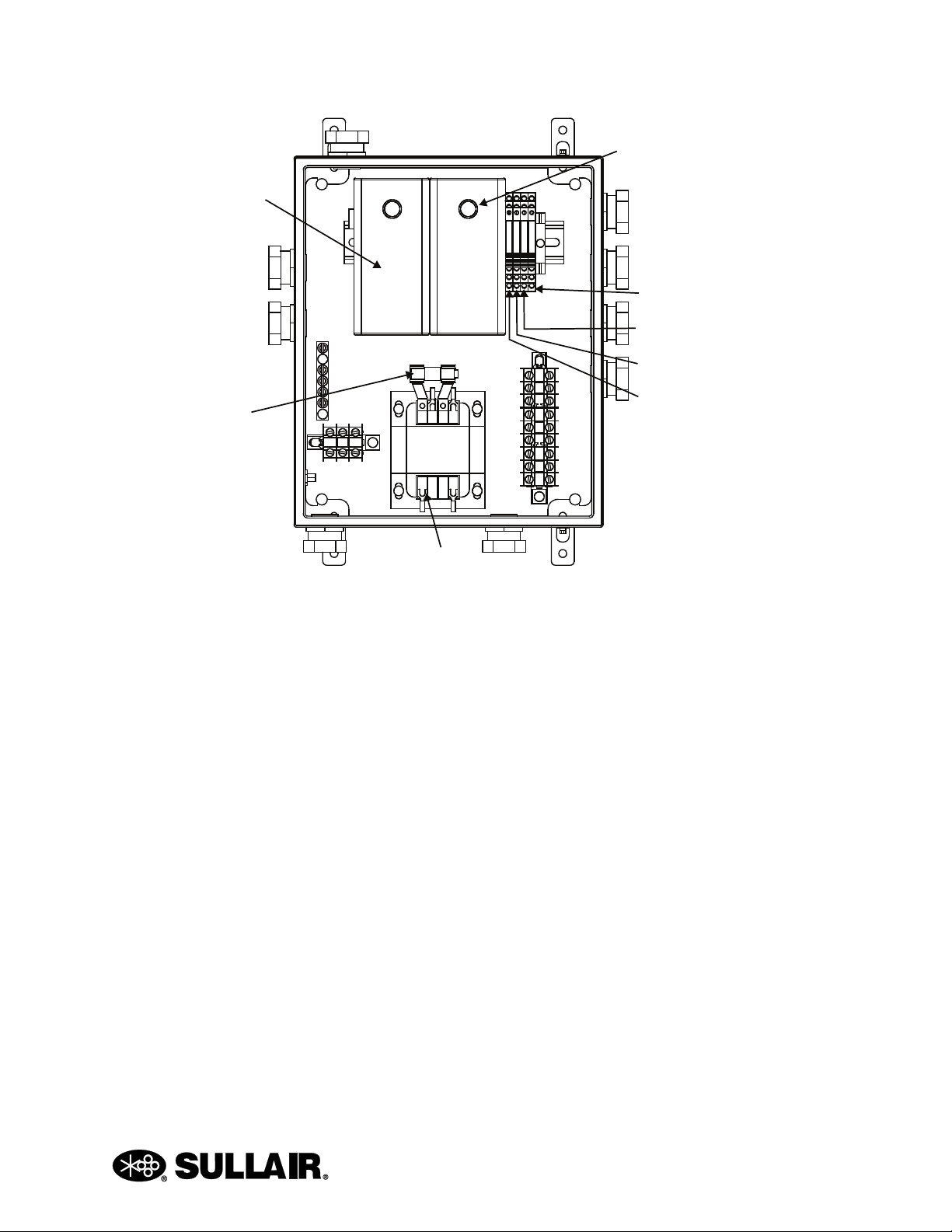
Figure 2-2: EES Control Enclosure
Proportional
Controller
Control Relay 3
Control Relay 2
Control Relay 1
Power Present Relay
Transformer
Outside Air
Temperature
Controller
Fuse

EES USER MANUAL SECTION 2
14
Heat of compression is recovered when:
• The temperature of the heated space is
less than the set value of room thermostat.
AND
• The temperature of the incoming outside
air is less than the set value of the outside
air temperature controller. Refer to Figure
2-3.
Heat of compression is rejected when:
• The temperature of the heated space is
higher than the set value of the room ther-
mostat. Refer to Figure 2-4.
Bypass Air
Damper
Incoming Air
Damper
Cooler
Mixed Air
Temperature Sensor
Recovered Air
Damper
To Heated
Space
Rejected
Air Damper
Outside Air
Temperature
Sensor
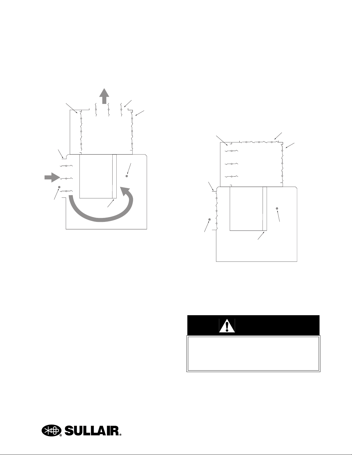
Figure 2-3: Low Room Temperature and
Low Outside Temperature
Bypass Air
Damper
To Outside
Incoming Air
Damper
Outside Air
Temperature Sensor
Cooler
Mixed Air
Temperature Sensor
Recovered Air
Damper
Rejected
Air Damper
Figure 2-4: High Room Temperature
SECTION 2 EES USER MANUAL
15
OR
• The temperature of the incoming outside
air is higher than the set value of the out-
side air temperature controller. Refer to
Figure 2-5.
Operation of the rejected and recovered air dampers
is accomplished with use of two position actuator
motors. Only one damper should ever be open at a
given time. When heat is being recovered, the
recovered damper opens while the rejected damper
closes. Conversely when heat is being rejected, the
rejected damper opens while the recovered damper
closes. Both actuators are spring return so when the
compressor does not have power or is on standby,
the actuators return to their normally closed
positions.
2.8 FUNCTIONAL DESCRIPTION
—POWER PRESENT RELAY
A power present relay (Figure 2-2) is used to prevent
unnecessary operation of the EES components. The
EES system will only operate when the compressor
is running. When power is not provided to the
compressor or when the compressor is in standby
mode and not running, there is no power to the EES
controls or motor actuators. Refer to Figure 2-6.
Upon compressor startup, a signal is sent from the
WS controller to the power present relay located in
the EES electrical enclosure. Power is then provided
to the controls and the EES will function normally.
Bypass Air
Damper
To Outside
Incoming Air
Damper
Outside Air
Temperature Sensor
Cooler
Mixed Air
Temperature Sensor
Recovered Air
Damper
Rejected
Air Damper
Figure 2-5: High Outside Temperature
WARNING
When the compressor is on standby there
is still power to the primary and secondary
leads on the transformer in the EES electri-
cal enclosure.
Bypass Air
Damper
Incoming Air
Damper
Outside Air
Temperature Sensor
Cooler
Mixed Air
Temperature Sensor
Recovered Air
Damper
Rejected
Air Damper
Figure 2-6: No Power or Standby

16
BLANK PAGE

Section 3
17
EES USER MANUAL
SPECIFICATIONS
3.1 TABLE OF SPECIFICATIONS—EES
Model Main
Motor HP
Package
Clean Air
Inlet
Option
Length Width Height
in mm in mm in mm
3000 40 Without 67.1 1703 34.5 876 98.3 2496
3000 40 With 70.9 1801 34.5 876 98.3 2496
3000P 40 Without 67.1 1703 34.5 876 98.3 2496
3000P 40 With 70.9 1801 34.5 876 98.3 2496
3700 50 Without 67.1 1703 34.5 876 98.3 2496
3700 50 With 70.9 1801 34.5 876 98.3 2496
4500 60 Without 67.1 1703 34.5 876 98.3 2496
4500 60 With 70.9 1801 34.5 876 98.3 2496
Standard Machines with EES
Model Motor Type Main Motor
HP
Weight
lbs kg
3000 ODP 40 2097 952
3000 TEFC 40 2163 982
3000P ODP 40 2272 1031
3000P TEFC 40 2338 1061
3700 ODP 50 2322 1054
3700 TEFC 50 2406 1092
4500 ODP 60 2472 1122
4500 TEFC 60 2549 1157

EES USER MANUAL SECTION 3
18
Variable Speed Machines
3000 VSD with EES
Main Motor
HP Motor Type Voltage Amps
Weight
lbs kg
40 ODP 460/60 72 2173 986
40 TEFC 460/60 72 2239 1016
40 ODP 575/60 52 2173 986
40 TEFC 575/60 52 2239 1016
3000P VSD with EES
Main Motor
HP Motor Type Voltage Amps
Weight
lbs kg
40 ODP 460/60 72 2348 1065
40 TEFC 460/60 72 2414 1095
40 ODP 575/60 52 2348 1065
40 TEFC 575/60 52 2414 1095
3700 VSD with EES
Main Motor
HP Motor Type Voltage Amps
Weight
lbs kg
50 ODP 460/60 72 2398 1088
50 TEFC 460/60 72 2482 1126
50 ODP 575/60 52 2450 1111
50 TEFC 575/60 52 2534 1150
4500 VSD with EES
Main Motor
HP Motor Type Voltage Amps
Weight
lbs kg
60 ODP 460/60 72 2640 1198
60 TEFC 460/60 72 2717 1233
60 ODP 575/60 52 2523 1145
60 TEFC 575/60 52 2575 1168

SECTION 3 EES USER MANUAL
19
Cooling Airflow
Model Main Motor
HP
Air Flow
(CFM), max
0.50 in w.g.
duct
restriction
3000 40 4800
3000P 40 4800
3700 50 4800
4500 60 5600
Electrical Ratings
EES Electrical Enclosure NEMA 4
Proportional Controller
Voltage
24VAC/DC
50/60 Hz
Class 2
Adjustment Range -30 to 130°F
(-35 to 55°C)
Outside Air Temperature Controller
Voltage
24VAC/DC
50/60 Hz
Class 2
Adjustment Range -30 to 130°F
(-35 to 55°C)
Thermostat
Voltage 24VAC
Adjustment Range 40 to 90°F (Heat Mode)
Proportional Actuator
Voltage
24VAC
50/60 Hz
Class 2
Power Consumption 13VA driving
5VA holding
Enclosure Rating NEMA 2
2-Position Actuator
Voltage
24VAC
50/60 Hz
Class 2
Power Consumption 25VA driving
8VA holding
Enclosure Rating NEMA 2

EES USER MANUAL SECTION 3
20
Figure 3-1: Identification—EES
02250175-281-R00
This manual suits for next models
3
Table of contents
Popular Heating System manuals by other brands


aldes
aldes VEX600 installation instructions

Mitsubishi Electric
Mitsubishi Electric FTC5 user guide

Toyostove
Toyostove Laser 30 Installation and operation instruction

Zehnder Rittling
Zehnder Rittling ComfoConnect KNX C manual

Armcor
Armcor 0AP900 Installation and operation manual

THERMOBILE
THERMOBILE IMAC 2000 S user manual

Viessmann
Viessmann Vitodens 100-W operating instructions

Kaysun
Kaysun KRE-1500DX1 Installation and maintenance manual

Thermrup
Thermrup HI616 instruction manual

Vectaire
Vectaire EVO250DC Installation, operating and maintenance instructions

Reversomatic
Reversomatic RHRV-D100A Installation and operating instructions

Aspira
Aspira Ecocomfort SAT 160 RF User instructions