Swegon bluMartin freeAir 100 User manual

Manual
[ G ] General
[ O ] Operation
[ I ] Installation
[ S ] Service

Kurzanleitung
Quick Start Guide
Switching On / Off
Press the on switch.
Start-up routine and self check can take a few minutes –turning
it off can take a few seconds. All LEDs will blink (all colors).
Comfort Level
Press the - Button repeatedly to change the Comfort Level.
More blue LEDs mean a more active operation (minimum
ventilation, humidity, CO2, cooling ... etc.). However, a change in
Comfort Level does not have to lead to the immediate increase in
fan speed.
Blinking or flashing blue LEDs indicate Service or Dehumidification
Operation.
Turbo / Sleep / Turbo Cool
Push the - Button until you hear 4 short beeps. This should be
selected if you wish to air out rooms at the highest device setting for
30 minutes. Push and hold the - Button longer and your
freeAir100 will pause for 90 minutes.
To start Turbo Cool Function for a maximum duration of 3 hours
push and hold the button yet longer for.
Beep
→Comfort Level
Beep
Beep
Beep
Beep
→Turbo
B
e
e
e
p
→Sleep
Beep
Beep
Beep
Beep
→Turbo Cool

General
1
[ G ]
Dear customer
We thank you for choosing the freeAir ventilation system. Please thoroughly read and follow this
manual.
After successful installation please select the desired Comfort Level to activate the device.
Proper operation is now taken care of by the sensors and the intelligent controller of your
freeAir 100.
Enjoy the ambiance offered by the right amount of fresh air.
Your bluMartin-Team

General
2
[ G ]
General
Safety –General
This manual is only valid for the fresh air system freeAir 100.
This manual is delivered as part of the device. Please keep this manual readily available.
Please make sure all persons operating the device are familiar with this manual. Please
observe all instructions given in this manual.
Installation, commissioning and servicing must only be performed by sufficiently qualified
persons.
Neglect to adhere to this manual will void the warranty.
Please also observe our general terms and conditions. Please see www.bluMartin.de/cos .
Safety –Icon
DANGER
This sign indicates danger by potentially deadly electrical shock.
DANGER
This sign indicates that instructions must be followed precisely in order to prevent personal or
material damage.
Warning
To avoid any property damage please pay special attention to this sign.

General
3
[ G ]
Notes
This sign emphasizes important information.
Safety indications
DANGER
•The device uses electrical power. Some parts of the device carry line voltage even several
minutes after unplugging the device.
•Never open the device while appliance is plugged in.
•Electrical installation as well as electrical service work must only be performed by qualified
personnel.
•Electrical installation has to be in accordance with the appropriate national association
or electrical code.
•The device may only be operated in good condition and unaltered condition.
•All instructions and notes with respect to maintenance (see Service paragraph) are to be
implicitly followed.
•Only operate if device is in good technical order.
In case of error or damages that constitute a safety issues turn the device off.
Prevent the device from being turned back on by unauthorized persons, and have the
device immediately repaired by a qualified technician.
•Use original bluMartin GmbH repair and service parts only.

General
4
[ G ]
Intended use
The freeAir 100 is a decentralized fresh air ventilation system with heat recovery. The purpose
of the device is to ventilate one or more rooms in apartments or houses. The device is installed
in an outside wall.
Expended air is drawn from the room the device is installed in. The air is drawn from other
rooms (such as kitchen or bathroom) in case the 2nd room extract option is installed.
Fresh and filtered air is returned to the room the device is installed in. The addition of the 2nd
room supply option enables fresh and filtered air return to an additional room for instance a bed
room.
Inappropriate use
The device is exclusively to be used for ventilation purposes.
It is not intended for drying buildings.
DANGER
Only air not containing flammable, explosive or corrosive components or air not containing any
other dangerous or hazardous components must be used for ventilating purposes.
Disposal
Dispose of the freeAir100 in accordance with your local rules, regulations or guide lines.
Please pay special attention to correctly sorted metal, plastics and electronics.

General
5
[ G ]
Transport and Storage
Components of the freeAir 100 may only be transported in the intended packaging. Packaging
must be protected from moisture.
Included in Shipping
Bare brickwork set (BOX + second room extract) Outside hood
freeAir 100 Front plate

General
6
[ G ]
Technical Data
Dimensions inside front 28 x 58 cm (front plate); 30 x 63 (front cover II)
Wall thickness 32 to 53 cm incl. stuck (other dimensions with accessories)
Air stream 8 to 100 m3/h
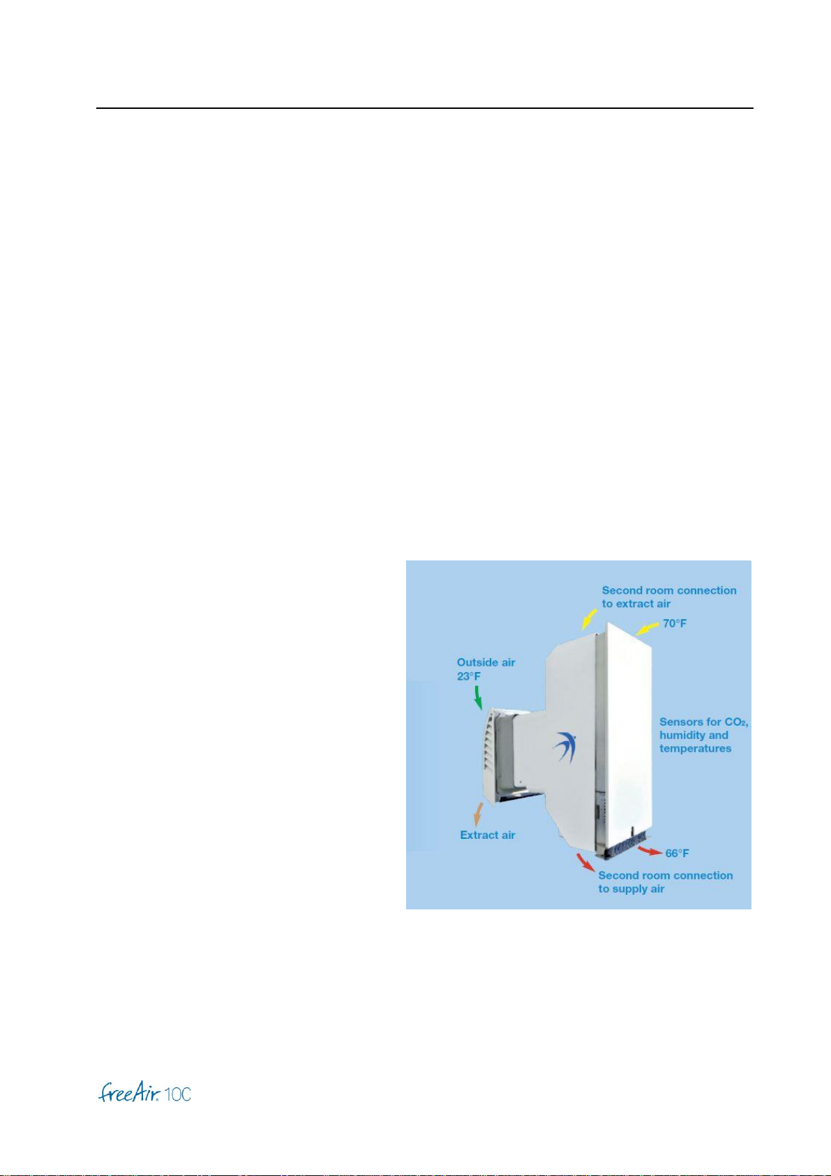
Heat supply gradient 87 % (by PHI criteria and EN 13141-8)
Heat recovery 94 % (at 50 % relative humidity)
Heat exchanger Cross counter flow; aluminum
Power grid connection 100 to 265 V AC; 45 to 65 Hz; internal fuse 3 A
Energy usage Standby → 1 W; 20 m3/h →4 W;
50 m3/h →9 W; 100 m3/h → 38 W (max. tube length)
Coefficient of performance typical 30 to 50 (energy production to energy usage)
Weight 10 kg
Noise level in room 20 m3/h →17 dB (A); 30 m3/h →22 dB (A);
(distance of 1 m) 50 m3/h →34 dB (A) with premium cover → 22 dB (A);
85 m3/h →with premium cover → 35 dB (A)
Noise dampening Standby → 52 dB (DIN EN 10140-2; Dn, e, w);
Operation → 46 dB (with premium cover max. 60 dB)
Control on demand Intelligent 5-level Comfort Control
Air stream control Automatic; continuously adjustable; constant capacity; balanced
CO2control Automatic
Moisture management Automatic (typical 40 to 60 % relative humidity)
Summer cooling Automatic and with Turbo Cool
Anti freeze protection Automatic bypass-control at about -5°C outside
Material temperature range -40 to +50°C outside and 0 to +40°C inside
Filter supply air (ISO 16890) Protect ePM10 (pollen) or Protect plus ePM1 (allergy)
Filter exhaust air (ISO 16890) Protect ePM10
Smart Home Connect WiFi; Connect USB
bluHome Connect (accessory for ModBus,KNX,BACnet,RS232)
Color Front plate white or primed (ready to paint or arrange)
Approvals DIBt: Z-51.3-287; Passiv house: 0641s03 and 1220s03

General
7
[ G ]
Product spec sheet –Directive 2009/125/EC
Supplier bluMartin GmbH
Ventilation model freeAir 100 –single room (non-ducted)
freeAir 100 –multiple room (ducted)
SEC-Class Single room: A+; -42.4 kWh/a m2
Multiple room: A+; -42.7 kWh/a m2
Model-Type Bidirectional residential ventilation unit
Drive-Type Variable speed drive
Heat recovery Recuperative
Thermal efficiency 87 %
Maximum flow rate 100 m3/h
Maximum power input 40 W
Sound power level Single room: 70 m3/h →48 dB (A); 20 m3/h →28 dB (A)
Multi room: 70 m3/h →47 dB (A); 20 m3/h →23 dB (A)
(with premium cover 12 dB less)
Reference flow rate 70 m3/h
Reference pressure difference 65 Pa
Specific power input Single room: 0.22 W/m3h
Multi room: 0.24 W/m3h
Control factor 0.65 (local demand control)
Internal leakage 1.7 % (at 100 m3/h and 50 Pa)
External leakage 3.2 % (at 100 m3/h and 100 Pa)
Mixing rate 3.5 %
Visual filter warning Red LED left and right side of device (dirty filters result
in diminished air flow as well as over or under pressure)
Internet address www.bluMartin.de
Sensitivity to pressure variations 3.0 %
Air tightness 3.2 m3/h (at 100 Pa)
Wessling, July 8th, 2020 Bernhard Martin

Operation
8
[ O ]
Operation
DANGER
Respect all references regarding safety and use of the freeAir 100 in part General [G]!
Display- and Operating Elements
on Main Switch
Use for turning the freeAir 100 on or off.
All LEDs will blink slow during start and self-test operation.
During a controlled „Shut Down“ LEDs will blink fast. Vent flaps
are being shut.
Warning
Wait to restart until all LEDs are off.
- Button
Operation of your freeAir 100 is so simple –you only need this
button as the only control element.
With this button you can control Comfort Level, start or stop the
Turbo, select Sleep or Dehumidification mode (see below).
You can change the Comfort Level by pushing - Button
several times fast. The more blue LEDs are lit the more active
the instrument controls (minimum ventilation, CO2, humidity,
cooling...).
Changing Comfort Level may not immediately change fan speed.

Operation
9
[ O ]
Audible Signals
A continuous beep-sound indicates occurrence of excessive
temperatures or harmful CO2-Concentrations.
(See part [S] Service).
Yellow LED
This LED will blink slowly during Turbo operation.
The LED will blink fast during Turbo Cool operation.
Continuous illumination indicates:
•reduced minimum ventilation due to active defrost function
eliminating room air humidification, or
•the freeAir pauses,
because outside air is so humid that room air condensation
could occur or
because outside temperatures are below -22°C (-30°F).
Blue LEDs
The number of illuminated blue LEDs indicates the selected
Comfort Level.
These LEDs will blink slowly during Sleep mode.
These LEDs will flash during Dehumidification mode.
Note
Blue LEDs will go dark after 3 minutes so as not to disturb you.
Push the - Button to “wake” them up.
Piep

Operation
10
[ O ]
Red LED
A fast blinking red LED indicates that the last filter change has
been more than 8,700 hours ago (~ 1 year).
A slow blinking red LED indicates that the air stream through a
dirty and partially clogged filter is impaired. A slow blinking red
LED can also indicate air stream obstructions such as
inappropriately dimensioned openings between spaces of supply
and extract air.
Continuous illumination indicates control error. (See appendix
[S] Service).
DANGER
•An overly dirty filter (indicated by the red LED) can reduce supply and extract air flow. This
in turn can lead to diminished air quality and over or under pressure in connected rooms.
•Neglecting of filter change indicator may result in growth of harmful microbes.
Note
Excessive dust, inside or outside of the building during the building phase, may require
a premature filter change.
The red LED will appear continuously if the WiFi of the freeAir has been activated using the
freeAir Connect USB but is not connected to the local WiFi router.
This may be due to the wrong WiFi name or password, too far from the router or a problem with
the router or the internet.
The WiFi function is available up from pcb version 9 (software version 2.02 and higher).

Operation
11
[ O ]
USB Port
The USB port on the left side of the device serves as
a connection to the (free to our customers)
freeAir-Connect USB software, for the activation of
the WiFi function and respective updates.
Note
Please visit our website at www.bluMartin.de for
updates under Service / Downloads.
Louver
The louver in the left part of the air output side can be rotated to
accommodate any desired blow direction.
Note
Air intentionally only discharges from the left side of the vent.
DANGER
Do not insert any foreign objects into the supply opening.
Premium Cover
For particularly noise-sensitive installations, this front panel
offers a noise reduction of 12 dB.
For the dismounting of the freeAir 100 lift the cover slightly and
then pull out forwards.

Operation
12
[ O ]
Comfort Operation
After switching it on the freeAir 100 will operate in Comfort mode.
In this mode the device will operate automatically:
If installed correctly the device will supply all connected living areas
with the right amount of fresh air. Minimum air flow, CO2 content,
relative and absolute humidity inside and out are all taken into
account.
Push the - Button several times to select Comfort Level 1 (one
LED). This is the quietest level and should be selected if you like a
quiet setting for instance for bed rooms.
Level 3 (3 LEDs are lit) is the normal setting for living rooms.
Turbo Operation
Push the - Button until you hear 4 short beeps. This model
should be selected if you wish to air out rooms at the highest
device setting for 30 minutes. Comfort operation will be restored
automatically after 30 minutes. Comfort Level can also be restored
via the - Button.
Sleep Mode
Push and hold the - Button until you hear 4 short beeps followed
by a very long beep. Your freeAir100 will pause for 90 minutes
before switching back to Comfort mode.
Beep
→Comfort Level
Beep
Beep
Beep
Beep
→Turbo
B
e
e
e
p
→Sleep
Beep
Beep
Beep
Beep
→Turbo Cool
15 seconds
Beep
Beep
Beep
→Dehumidification

Operation
13
[ O ]
Turbo Cool Operation
The cooling function of your freeAir 100 is completely self-acting.
First, at high outside temperatures the heat exchanger operates as a cold exchanger, so the
summer heat stays outside, if you keep the windows and doors closed as in winter.
When sufficient average summer temperatures are reached, after one day your freeAir 100 is
switching into summer operation automatically. The device uses the fresh night air for cooling
by opening the bypass flap, thereby increasing the airflow.
Start Turbo Cool operation (and hereby switching into the summer operation) by pushing and
holding the - Button till you hear 4 short beeps followed by a long beep followed again by 4
short beeps. This will open the bypass flap and switch the device to its highest power setting for
3 hours. In this setting your living space can be cooled down noticeably by fresh evening and
night air after a hot day.
Turbo Cool operation is switched off automatically when outside air temperature is too hot.
Dehumidification Operation
Push and hold the - Button for 15 seconds to activate this mode. This operation can be used
in case of an application where the usual dehumidification level provided by the Comfort mode
is not sufficient (for instance in a basement room). The freeAir100 will beep three times and
blue LEDs will flash. Dehumidification will work at humidity levels as low as 45 % relative
humidity.
Dehumidification is optimally controlled through constant measuring of absolute humidity both
inside and outside effectively suppressing humidity import through outside air. Thereby the
ventilation is increasing to assure evacuation of humidity, as soon as absolute humidity inside
the building is higher than outside.

Installation –Bare Brickwork Set
14
[ I ]
Installation –Bare Brickwork Set
Visit our website for more help and the installation video:
www.blumartin.de/installateure/
DANGER
Please see part General [G] for safety notes. Observe all notes with respect to safety and use of
the freeAir 100.
2nd Room Connections
1. Please select the correct connector for a device designed for
2nd room connection:
•Connecting ducting, conduits and valves must have
low air stream resistance.
•For 2nd room connection the below stated decrease
in pressure must not be exceeded.
•The supply air conduits must not exceed
the below noted length.
Type of Conduit
Max. Air Flow for
2nd Room Exhaust
(= DIP switch setting)
Max. Pressure drop
2nd Room Exhaust
(at max. air flow)
=> Max. Length
(pressure drop for turns and
valves included)
1 x Flat-Flex 51 x 138 mm
30 m3/h
15 Pa
ca. 8 m
1 x Round-Flex 75 mm
30 m3/h
15 Pa
ca. 2.5 m
2 x Round-Flex 75 mm
60 m3/h
55 Pa
ca. 10 m
3 x Round-Flex 75 mm
100 m3/h
65 Pa
ca. 10 m
1 x Round 100 mm
100 m3/h
65 Pa
ca. 12 m

Installation –Bare Brickwork Set
15
[ I ]
Notes
•The freeAir 100 compensates for air stream resistance, due to connected conduit or dirty
filter, by increasing fan speed.
•Therefore supply and exhaust air stream remain constant and balanced.
•“Dirty Filter” error will be indicated once maximum fan speed is reached.
•Longer supply ducting will result in a change in balance between the air flow of the 1st and
2nd room in favor of the 1st room (normal 1 : 1).
2. Open the appropriate passage and attach the appropriate
ductings or connectors by taking care to use an O-ring or
sealant.
Note
In case of the bare brickwork set with BOX, just remove
the plugs,
for the bare brickwork set without BOX the openings have
to be cut.
3. Use the included adapter, if you wish to connect another
Round-Flex 75 mm to the 2nd room exhaust adapter.
Note
For the bare brickwork set with BOX, this adapter must be
separated.
In case of the bare brickwork set without BOX,
a fourth Round-Flex-Duct can be added using a Flat-Flex-
Round-Flex-Adapter.

Installation –Bare Brickwork Set
16
[ I ]
4. Allow for sufficient openings between rooms (clearance
between door frame and door leaf) and sufficiently sized
supply and exhaust valves:
Air Flow
Minimal Cross Section Area
30 m3/h
30 cm2(Valve Ø 125 mm)
60 m3/h
60 cm2 (Valve Ø 125 mm, fully opened)
100 m3/h
100 cm2(Valve Ø 200 mm)
Installation Side
DANGER
•The freeAir 100 must not be installed in immediate vicinity of easy inflammable material or
harmful chemicals.
•During planning consider all relevant local building, safety and fire codes. Especially in
situations where indoor air is used for combustion (wood stove, fire place...etc.).
Warning
The freeAir 100 is not 100% suitable for tropical locations with high humidity. In such locations
condensate could result on the inside part of the device (the freeAir will pause in these cases).
The system has yet no design features allowing drainage from the inside.
Room temperature during operation should be between 0°C and 40°C.
Outside temperature should be between -40°C and +50°C.

Installation –Bare Brickwork Set
17
[ I ]
Installation Side - Condensate Drain
If designated condensate drain hose cannot be used, device
location must be selected such that condensing water can freely
drain to the outside. Make sure that neither falling icicles nor
freezing run-off create any hazards.
Notes
•The formation of ice can be reduced with the software option de-icing
(only with the permission of the owner of the building).
•Even with the condensate drain connected, under certain conditions, small amounts of
water droplets may emerge at the outside hood.

Installation –Bare Brickwork Set
18
[ I ]
Drawings
Table of contents
Other Swegon Heating System manuals
Popular Heating System manuals by other brands

Vortice
Vortice VORT HR 350 AVEL Instruction booklet

Trotec
Trotec IDE 30 operating manual

ThermaWave
ThermaWave Gobi owner's manual

Titon
Titon HRV1 Q Plus product manual

Roberts Gorden
Roberts Gorden Dualair DA260G Series Installation, comissioning, service & user instructions

Lincar
Lincar Alice 480N Using instructions and maintenance