sullar 30XH User manual

Failure to follow the instructions
and procedures in this manual or,
misuse of this equipment will
VOID its warranty!
WARRANTY NOTICE
PART NUMBER:
KEEP FOR
FUTURE
REFERENCE
USER MANUAL
©SULLAIR CORPORATION
The information in this manual is current
as of its publication date and applies to
compressor serial number :
and all subsequent serial numbers.
02250184-779 R00
200903010000
ROTARY SCREW AIR COMPRESSOR
ES-8 SERIES MOBILE APPLICATION

AIR CARE SEMINAR TRAINING
Sullair Air Care Seminars are courses that provide hands-on instruction for the proper operation, maintenance,
and servicing of Sullair products. Individual seminars on Industrial compressors and compressor electrical
systems are offered at regular intervals throughout the year at Sullair’s corporate headquarters training facility
located at Michigan City, Indiana.
Instruction includes training on the function and installation of Sullair service parts, troubleshooting common
faults and malfunctions, and actual equipment operation. These seminars are recommended for maintenance,
contractor maintenance, and service personnel.
For detailed course outlines, schedule, and cost information contact:
SULLAIR CUSTOMER CARE TRAINING DEPARTMENT
1-888-SULLAIR or
219-879-5451 (ext. 5623)
www.sullair.com
- Or Write -
Sullair Corporation
3700 E. Michigan Blvd.
Michigan City, IN 46360
Attn: Service Training Department.

TABLE OF CONTENTS
SECTION 1—SAFETY
5 1.1 GENERAL
5 1.2 PERSONAL PROTECTIVE EQUIPMENT
5 1.3 PRESSURE RELEASE
6 1.4 FIRE AND EXPLOSION
6 1.5 MOVING PARTS
7 1.6 HOT SURFACES, SHARP EDGES AND SHARP CORNERS
7 1.7 TOXIC AND IRRITATING SUBSTANCES
8 1.8 ELECTRICAL SHOCK
8 1.9 LIFTING
9 1.10 ENTRAPMENT
SECTION 2—INSTALLATION
11 2.1 LOCATION OF COMPRESSOR
11 2.2 VENTILATION AND COOLING
11 2.3 SERVICE AIR PIPING
12 2.4 COUPLING ALIGNMENT CHECK
12 2.5 FLUID LEVEL CHECK
12 2.6 MOTOR ROTATION DIRECTION CHECK
12 2.7 ELECTRICAL PREPARATION
SECTION 3—SPECIFICATIONS
13 3.1 TABLE OF SPECIFICATIONS
13 3.2 COMPRESSOR SPECIFICATIONS
13 3.3 MOTOR SPECIFICATIONS
13 3.4 FLUID FILTER
13 3.5 FLUID SEPARATOR ELEMENT
14 3.6 LUBRICATION GUIDE
14 3.7 LUBRICATION CHANGE RECOMMENDATIONS & MAINTENANCE
SCHEDULE

TABLE OF CONTENTS
SECTION 4—COMPRESSOR SYSTEMS
15 4.1 INTRODUCTION
15 4.2 DESCRIPTION OF COMPONENTS
15 4.3 ENCAPSULATED COMPRESSOR SYSTEM, FUNCTIONAL DESCRIP-
TION
16 4.4 COMPRESSOR COOLING SYSTEM, FUNCTIONAL DESCRIPTION
16 4.5 AIR INLET SYSTEM, FUNCTIONAL DESCRIPTION
17 4.6 CONTROL SYSTEM, FUNCTIONAL DESCRIPTION
SECTION 5—WS CONTROLLER
19 5.1 CONTROLLER LAYOUT
19 5.2 CONTROLLER KEYPAD
20 5.3 LCD DISPLAY
21 5.4 LED LIGHTS
SECTION 6—MAINTENANCE
23 6.1 INTRODUCTION
23 6.2 DAILY OPERATION
23 6.3 MOTOR BEARING LUBRICATION
23 6.4 FLUID FILTER MAINTENANCE
24 6.5 COOLER MAINTENANCE
24 6.6 PARTS REPLACEMENT AND ADJUSTMENT PROCEDURES
28 6.7 MAINTENANCE RECORD
SECTION 7—TROUBLESHOOTING
29 7.1 INTRODUCTION
SECTION 8—PARTS LIST
31 8.1 PROCEDURE FOR ORDERING PARTS
32 8.2 RECOMMENDED SERVICE PARTS LIST
34 8.3 INLET CONTROL, SEAL/DRIVE GEAR AND PARTS
36 8.4 MOTOR, COUPLING, FAN AND PARTS
38 8.5 INLET FILTER, COMPRESSOR HOUSING/SUMP AND PARTS
40 8.6 COMPRESSOR COOLER SYSTEM AND PARTS
42 8.7 PNEUMATIC CONTROL SYSTEM AND PARTS
44 8.8 CONTROL STARTER—MFV
46 8.9 DECAL GROUP
50 8.10 WIRING DIAGRAM—FULL VOLTAGE (STANDARD)

Section 1
5
SAFETY
1.1 GENERAL
Sullair Corporation and its subsidiaries design and
manufacture all of their products so they can be
operated safely. However, the responsibility for safe
operation rests with those who use and maintain
these products. The following safety precautions are
offered as a guide which, if conscientiously followed,
will minimize the possibility of accidents throughout
the useful life of this equipment.
The compressor should be operated only by those
who have been trained and delegated to do so, and
who have read and understood this Operator's
Manual. Failure to follow the instructions, procedures
and safety precautions in this manual may result in
accidents and injuries. NEVER start the compressor
unless it is safe to do so. DO NOT attempt to operate
the compressor with a known unsafe condition. Tag
the compressor and render it inoperative by
disconnecting and locking out all power at source or
otherwise disabling its prime mover so others who
may not know of the unsafe condition cannot attempt
to operate it until the condition is corrected.
Install, use and operate the compressor only in full
compliance with all pertinent OSHA regulations and/
or any applicable Federal, State, and Local codes,
standards and regulations. DO NOT modify the
compressor and/or controls in any way except with
written factory approval.
While not specifically applicable to all types of
compressors with all types of prime movers, most of
the precautionary statements contained herein are
applicable to most compressors and the concepts
behind these statements are generally applicable to
all compressors.
1.2 PERSONAL PROTECTIVE
EQUIPMENT
A. Prior to installing or operating the compressor,
owners, employers and users should become
familiar with, and comply with, all applicable
OSHA regulations and/or any applicable Federal,
State and Local codes, standards, and regula-
tions relative to personal protective equipment,
such as eye and face protective equipment,
respiratory protective equipment, equipment
intended to protect the extremities, protective
clothing, protective shields and barriers and elec-
trical protective equipment, as well as noise
exposure administrative and/or engineering con-
trols and/or personal hearing protective equip-
ment.
1.3 PRESSURE RELEASE
A. Install an appropriate flow-limiting valve between
the service air outlet and the shut-off (throttle)
valve, either at the compressor or at any other
point along the air line, when an air hose exceed-
ing 1/2" (13mm) inside diameter is to be con-
nected to the shut-off (throttle) valve, to reduce
pressure in case of hose failure, per OSHA Stan-
dard 29 CFR 1926.302(b)(7) and/or any applica-
ble Federal, State and Local codes, standards
and regulations.
B. When the hose is to be used to supply a mani-
fold, install an additional appropriate flow-limiting
valve between the manifold and each air hose
exceeding 1/2" (13mm) inside diameter that is to
be connected to the manifold to reduce pressure
in case of hose failure.
C. Provide an appropriate flow-limiting valve at the
beginning of each additional 75 feet (23m) of
hose in runs of air hose exceeding 1/2" (13mm)
NOTE
OPERATOR IS REQUIRED TO READ
ENTIRE INSTRUCTION MANUAL.

SECTION 1
6
inside diameter to reduce pressure in case of
hose failure.
D. Flow-limiting valves are listed by pipe size and
flow-rated. Select appropriate valves accordingly,
in accordance with their manufacturer's recom-
mendations.
E. DO NOT use air tools that are rated below the
maximum rating of the compressor. Select air
tools, air hoses, pipes, valves, filters and other
fittings accordingly. DO NOT exceed manufac-
turer's rated safe operating pressures for these
items.
F. Secure all hose connections by wire, chain or
other suitable retaining device to prevent tools or
hose ends from being accidentally disconnected
and expelled.
G. Open fluid filler cap only when compressor is not
running and is not pressurized. Shut down the
compressor and bleed the receiver tank to zero
internal pressure before removing the cap.
H. Vent all internal pressure prior to opening any
line, fitting, hose, valve, drain plug, connection or
other component, such as filters and line oilers,
and before attempting to refill optional air line
anti-icer systems with antifreeze compound.
I. Keep personnel out of line with and away from
the discharge opening of hoses or tools or other
points of compressed air discharge.
J. DO NOT use air at pressures higher than 2.1 bar
for cleaning purposes, and then only with effec-
tive chip guarding and personal protective equip-
ment per OSHA Standard 29 CFR 1910.242 (b)
and/or any applicable Federal, State, and Local
codes, standards and regulations.
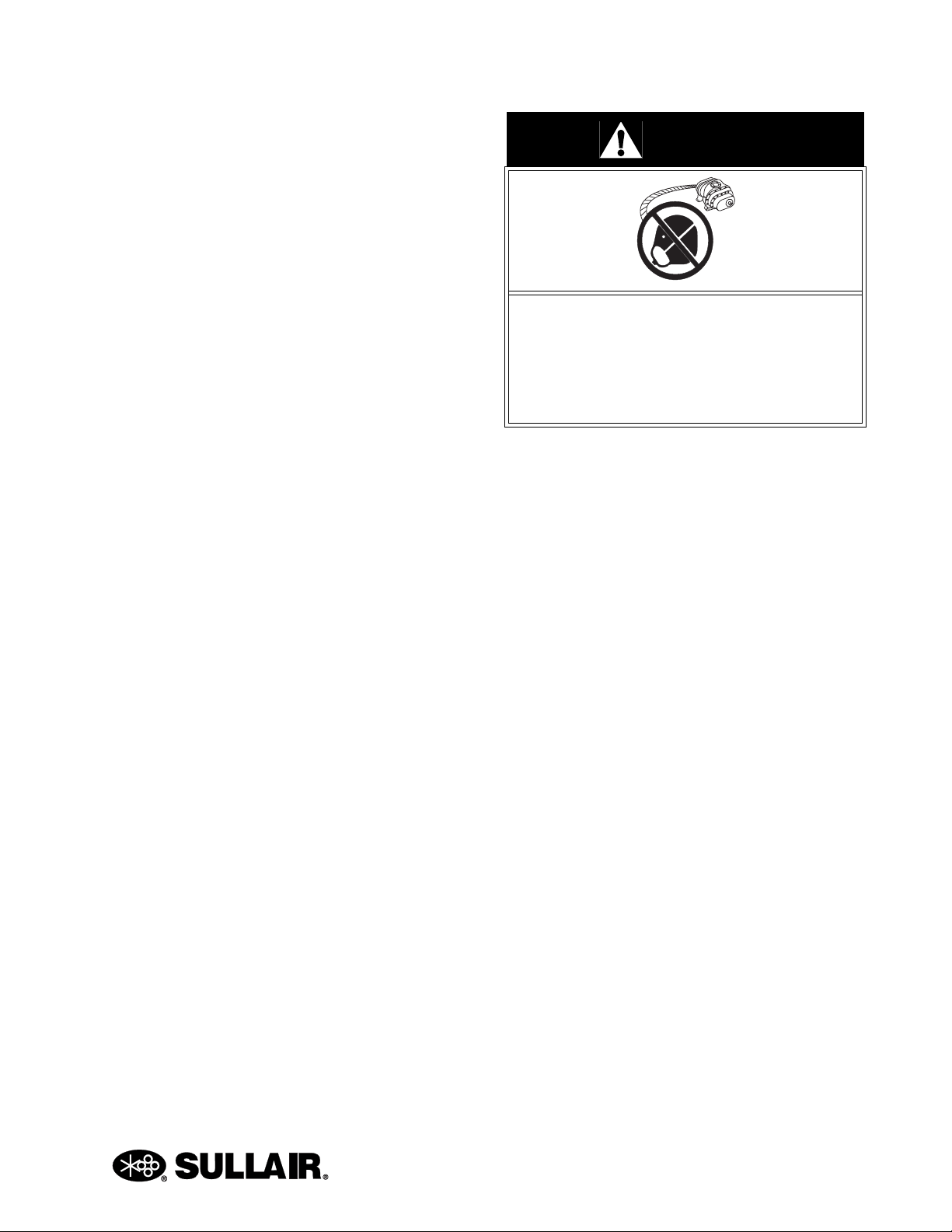
K. DO NOT engage in horseplay with air hoses as
death or serious injury may result.
1.4 FIRE AND EXPLOSION
A. Clean up spills of lubricant or other combustible
substances immediately, if such spills occur.
B. Shut off the compressor and allow it to cool.
Then keep sparks, flames and other sources of
ignition away and DO NOT permit smoking in the
vicinity when checking or adding lubricant or
when refilling air line anti-icer systems with anti-
freeze compound.
C. DO NOT permit fluids, including air line anti-icer
system antifreeze compound or fluid film, to
accumulate on, under or around acoustical mate-
rial, or on any external surfaces of the air com-
pressor. Wipe down using an aqueous industrial
cleaner or steam clean as required. If necessary,
remove acoustical material, clean all surfaces
and then replace acoustical material. Any acous-
tical material with a protective covering that has
been torn or punctured should be replaced
immediately to prevent accumulation of liquids or
fluid film within the material. DO NOT use flam-
mable solvents for cleaning purposes.
D. Disconnect and lock out all power at source prior
to attempting any repairs or cleaning of the com-
pressor or of the inside of the enclosure, if any.
E. Keep electrical wiring, including all terminals and
pressure connectors in good condition. Replace
any wiring that has cracked, cut, abraded or oth-
erwise degraded insulation, or terminals that are
worn, discolored or corroded. Keep all terminals
and pressure connectors clean and tight.
F. Keep grounded and/or conductive objects such
as tools away from exposed live electrical parts
such as terminals to avoid arcing which might
serve as a source of ignition.
G. Remove any acoustical material or other material
that may be damaged by heat or that may sup-
port combustion and is in close proximity, prior to
attempting weld repairs.
H. Keep suitable fully charged Class BC or ABC fire
extinguisher or extinguishers nearby when ser-
vicing and operating the compressor.
I. Keep oily rags, trash, leaves, litter or other com-
bustibles out of and away from the compressor.
J. DO NOT operate the compressor without proper
flow of cooling air or water or with inadequate
flow of lubricant or with degraded lubricant.
K. DO NOT attempt to operate the compressor in
any classification of hazardous environment
unless the compressor has been specially
designed and manufactured for that duty.
1.5 MOVING PARTS
A. Keep hands, arms and other parts of the body
and clothing away from couplings, belts, pulleys,
fans and other moving parts.
B. DO NOT attempt to operate the compressor with
the fan, coupling or other guards removed.

SECTION 1
7
C. Wear snug-fitting clothing and confine long hair
when working around this compressor, especially
when exposed to hot or moving parts.
D. Keep access doors, if any, closed except when
making repairs or adjustments.
E. Make sure all personnel are out of and/or clear of
the compressor prior to attempting to start or
operate it.
F. Disconnect and lock out all power at source and
verify at the compressor that all circuits are de-
energized to minimize the possibility of acciden-
tal start-up, or operation, prior to attempting
repairs or adjustments. This is especially impor-
tant when compressors are remotely controlled.
G. Keep hands, feet, floors, controls and walking
surfaces clean and free of fluid, water or other
liquids to minimize the possibility of slips and
falls.
1.6 HOT SURFACES, SHARP
EDGES AND SHARP
CORNERS
A. Avoid bodily contact with hot fluid, hot coolant,
hot surfaces and sharp edges and corners.
B. Keep all parts of the body away from all points of
air discharge.
C. Wear personal protective equipment including
gloves and head covering when working in, on or
around the compressor.
D. Keep a first aid kit handy. Seek medical assis-
tance promptly in case of injury. DO NOT ignore
small cuts and burns as they may lead to infec-
tion
1.7 TOXIC AND IRRITATING
SUBSTANCES
A. DO NOT use air from this compressor for respi-
ration (breathing) except in full compliance with
OSHA Standards 29 CFR 1910 and/or any appli-
cable Federal, State or Local codes or regula-
tions.
B. DO NOT use air line anti-icer systems in air lines
supplying respirators or other breathing air utili-
zation equipment and DO NOT discharge air
from these systems into unventilated or other
confined areas.
C. Operate the compressor only in open or ade-
quately ventilated areas.
D. Locate the compressor or provide a remote inlet
so that it is not likely to ingest exhaust fumes or
other toxic, noxious or corrosive fumes or sub-
stances.
E. Coolants and lubricants used in this compressor
are typical of the industry. Care should be taken
to avoid accidental ingestion and/or skin contact.
In the event of ingestion, seek medical treatment
promptly. Wash with soap and water in the event
of skin contact. Consult Material Safety Data
Sheet for information pertaining to fluid of fill.
F. Wear goggles or a full face shield when adding
antifreeze compound to air line anti-icer systems.
G. If air line anti-icer system antifreeze compound
enters the eyes or if fumes irritate the eyes, they
should be washed with large quantities of clean
water for fifteen minutes. A physician, preferably
an eye specialist, should be contacted immedi-
ately.
H. DO NOT store air line anti-icer system antifreeze
compound in confined areas.
I. The antifreeze compound used in air line anti-
freeze systems contains methanol and is toxic,
harmful or fatal if swallowed. Avoid contact with
the skin or eyes and avoid breathing the fumes. If
DANGER
Death or serious injury can result from
inhaling compressed air without using
proper safety equipment. See OSHA stan-
dards and/or any applicable Federal, State,
and Local codes, standards and regulations
on safety equipment.

SECTION 1
8
swallowed, induce vomiting by administering a
tablespoon of salt, in each glass of clean, warm
water until vomit is clear, then administer two
teaspoons of baking soda in a glass of clean
water. Have patient lay down and cover eyes to
exclude light. Call a physician immediately.
1.8 ELECTRICAL SHOCK
A. This compressor should be installed and main-
tained in full compliance with all applicable Fed-
eral, State and Local codes, standards and
regulations, including those of the National Elec-
trical Code, and also including those relative to
equipment grounding conductors, and only by
personnel that are trained, qualified and dele-
gated to do so.
B. Keep all parts of the body and any hand-held
tools or other conductive objects away from
exposed live parts of electrical system. Maintain
dry footing, stand on insulating surfaces and DO
NOT contact any other portion of the compressor
when making adjustments or repairs to exposed
live parts of the electrical system. Make all such
adjustments or repairs with one hand only, so as
to minimize the possibility of creating a current
path through the heart.
C. Attempt repairs in clean, dry and well lighted and
ventilated areas only.
D. DO NOT leave the compressor unattended with
open electrical enclosures. If necessary to do so,
then disconnect, lock out and tag all power at
source so others will not inadvertently restore
power.
E. Disconnect, lock out, and tag all power at source
prior to attempting repairs or adjustments to
rotating machinery and prior to handling any
ungrounded conductors.
1.9 LIFTING
A. If the compressor is provided with a lifting bail,
then lift by the bail provided. If no bail is provided,
then lift by sling. Compressors to be air-lifted by
helicopter must not be supported by the lifting
bail but by slings instead. In any event, lift and/or
handle only in full compliance with OSHA stan-
dards 29 CFR 1910 subpart N and/or any appli-
cable Federal, State, and Local codes, standards
and regulations.
B. Inspect points of attachment for cracked welds
and for cracked, bent, corroded or otherwise
degraded members and for loose bolts or nuts
prior to lifting.
C. Make sure entire lifting, rigging and supporting
structure has been inspected, is in good condi-
tion and has a rated capacity of at least the
weight of the compressor. If you are unsure of
the weight, then weigh compressor before lifting.
D. Make sure lifting hook has a functional safety
latch or equivalent, and is fully engaged and
latched on the bail or slings.
E. Use guide ropes or equivalent to prevent twisting
or swinging of the compressor once it has been
lifted clear of the ground.
F. DO NOT attempt to lift in high winds.
G. Keep all personnel out from under and away
from the compressor whenever it is suspended.
H. Lift compressor no higher than necessary.
DANGER
All field equipment must be tested for elec-
trostatic fields prior to servicing or making
contact with the machine using the follow-
ing or equivalent test equipment:
• 90-600 VAC: Volt detector such as
Fluke Model 1AC-A
• 600-7000 VAC: Voltage detector
such as Fluke Networks Model
C9970
It is the responsibility of each organization
to provide/arrange training for all their
associates expected to test for electrostatic
fields.

SECTION 1
9
I. Keep lift operator in constant attendance when-
ever compressor is suspended.
J. Set compressor down only on a level surface
capable of safely supporting at least its weight
and its loading unit.
K. When moving the compressor by forklift truck,
utilize fork pockets if provided. Otherwise, utilize
pallet if provided. If neither fork pockets or pallet
are provided, then make sure compressor is
secure and well balanced on forks before
attempting to raise or transport it any significant
distance.
L. Make sure forklift truck forks are fully engaged
and tipped back prior to lifting or transporting the
compressor.
M. Forklift no higher than necessary to clear obsta-
cles at floor level and transport and corner at
minimum practical speeds.
N. Make sure pallet-mounted compressors are
firmly bolted or otherwise secured to the pallet
prior to attempting to forklift or transport them.
NEVER attempt to forklift a compressor that is
not secured to its pallet, as uneven floors or sud-
den stops may cause the compressor to tumble
off, possibly causing serious injury or property
damage in the process.
1.10 ENTRAPMENT
A. If the compressor enclosure, if any, is large
enough to hold a man and if it is necessary to
enter it to perform service adjustments, inform
other personnel before doing so, or else secure
and tag the access door in the open position to
avoid the possibility of others closing and possi-
bly latching the door with personnel inside.
B. Make sure all personnel are out of compressor
before closing and latching enclosure doors.

NOTES
10

Section 2
ES-8 MOBILE APPLICATION MANUAL R00
11
INSTALLATION
2.1 LOCATION OF
COMPRESSOR
The ES-8 Series compressor package may be
placed on any level surface able to support its
weight. The unit is mounted on vibration mounts and
can be bolted to a fixed mounting surface to avoid
the possibility of externally applied forces or vibration
which would disturb the piping or wiring.
2.2 VENTILATION AND
COOLING
Select a location to permit sufficient unobstructed air
flow in and out of the compressor to keep the
operating temperature stable. The minimum
distance that the machine should be from
surrounding walls and ceiling is what is needed
for service and three (3) feet (914mm) or more
from the compressor fluid cooler.
2.3 SERVICE AIR PIPING
Service air piping should be installed as shown in
Figure 2-1. A shut-off valve should be installed to
isolate the compressor from the service line. Also
notice that the service line should be equipped with
water legs and condensate drains throughout the
system.
WARNING
“The Plastic Pipe Institute recommends
against the use of thermoplastic pipe to
transport compressed air or other com-
pressed gases in exposed above ground
locations, e.g. in exposed plant piping.” (I)
Sullube 32 should not be used with PVC
piping systems. It may affect the bond at
cemented joints.Certain other plastic mate-
rials may also be affected.
(I) Plastic Pipe Institute, Recommendation
B, Adopted January 19, 1972.
Figure 2-1: Service Air Piping

ES-8 MOBILE APPLICATION MANUAL R00 SECTION 2
12
2.4 COUPLING ALIGNMENT
CHECK
With the compressor unit directly flange-mounted to
its drive, the coupling supplied with the compressor is
always properly aligned for opertion. However, we
recommend that you re-check the coupling gap
before start-up or when handling the unit. a 1.5 to
3mm axial clearance should be maintained for the
coupling gap. See Section 6.4.
2.5 FLUID LEVEL CHECK
The Sullair air compressor is equipped with the
proper amount of fluid. However, it is necessary to
check the fluid level at installation. The level is
checked by looking at the fluid level sight tube
located on the end bell. If the sump is properly filled,
the fluid level should cover 1/4 to 1/2 of the level
range during operation. With the compressor shut
down, the level should be 3/4 of the sight tube. DO
NOT overfill.
2.6 MOTOR ROTATION
DIRECTION CHECK
After the electrical wiring has been done, it is
necessary to check the direction of the motor
rotation.
Pull out the EMERGENCY STOP button and press
once, quickly and in succession, the (START) Iand
(STOP) Opads. This action will bump start the motor
for a very short time. When looking at the motor from
the control panel side, view the coupling by looking
through the air inlet duct on the lower side of the
adapter fan housing. The coupling should be turning
clockwise. If the reversed rotation is noted,
disconnect the power to the starter and exchange
any two of the three power input leads, then re-
check rotation. A “Direction of Rotation” decal is
located on the motor and cooler shroud to show
proper motor/compressor rotation.
2.7 ELECTRICAL PREPARATION
Interior electrical wiring is performed at the factory.
Required customer wiring is minimal, but should be
done by a qualified electrician in compliance with
OSHA, National Electrical Code, and/or any other
applicable State, Federal and local electrical codes
concerning isolation switches, fused disconnects,
etc. Sullair provides a wiring diagram for use by the
installer.
A few electrical checks should be made to help
assure that the first start-up will be trouble-free.
1. Check incoming voltage. Be sure that com-
pressor is wired for the correct incoming volt-
age.
2. Check starter for correct size, proper over-
load relay, and heaters.
3. Check all electrical connections for tight-
ness.
4. “DRY RUN” the electrical controls by discon-
necting the three (3)motor leads from the
starter. Pull out the EMERGENCY STOP
button on the control panel.
5. Reconnect the motor leads and jog the
motor for a direction of rotation check as
explained in Section 2.6.
NOTE
Customer must provide electrical supply
power disconnect within sight of machine.
WARNING
Lethal shock hazard inside. Disconnect all
power at source before opening or servicing.
NOTE
Wiring diagram for standard compressors
is supplied on the inside cover of the
Control Center. Optional compressor wir-
ing diagrams will vary.

Section 3
ES-8 MOBILE APPLICATION MANUAL R00
13
SPECIFICATIONS
3.1 TABLE OF SPECIFICATIONS
3.2 COMPRESSOR SPECIFICATIONS
3.3 MOTOR SPECIFICATIONS
3.4 FLUID FILTER
3.5 FLUID SEPARATOR ELEMENT
60 HZ
Model HP ACFM PSIG
DIMENSIONS
Length Width Height Weight dBA (I)
in mm in mm in mm lbs kg w/Encls./
w/o Encls.
30XH 30 95 185 52 32 32 1065 78/85
(I) Ratings for dBA at one meter.
COMPRESSOR:
Type: SIngle Stage Fluid Injected Screw Compressor
Minimum Full Load Operating Pressure: 60 psig (4.2 bar)
Maximum Full Load Operating Pressure: Nameplate Pressure
Bearing Type: Anti-friction
Cooling: Pressurized Fluid
Lubricant: see Section 3.7: Lubrication Change Recommendations &
Maintenance Schedule
Sump Capacity: 3 gallons (11.4 liters)
MOTOR: 60 Hz
Type: TEFC, C-flange
Synchronous Speed: 30 HP = 3600 RPM
Voltage:
Standard All Sizes: 460
Type:
Insulation Class: B- (Min.)
Maximum Ambient Temp.: 50ºC (122ºF)
Fluid Filter
Type: Spin on, Sullair Proprietary
Micron: 23 Microns Abs.
Internal Bypass Valve Set at 25 psig (1.7 bar):
Fluid Separator Element
Type: Push In Cartridge, Sullair Proprietary
Efficiency at Maximum Capacity: 5PPM Maximum

ES-8 MOBILE APPLICATION MANUAL R00 SECTION 3
14
3.6 LUBRICATION GUIDE
For best value and longest uninterrupted service, the
ES-8 compressor is factory filled and tested with a
long life lubricant.
Maintenance of all other components is still
recommended as indicated in the Operator’s Manual.
For light-duty high-humidity service where
condensed moisture and emulsification
(mayonnaise) may occur, the fluid change interval
must be reduced to 300 hours maximum. A non-
detergent fluid with rust, oxidation and foam
inhibitors and good water separation characteristics
should be used.
DO NOT MIX DIFFERENT TYPES OF FLUIDS.
Contamination of non-detergent mineral fluids with
traces of ATF or detergent motor fluids may lead to
operational problems such as foaming, filter
plugging, orifice or line plugging.
When ambient conditions exceed those noted or if
conditions warrant use of “extended” life lubricants
contact Sullair for recommendation.
Sullair encourages the user to participate in a fluid
analysis program. This could result in a fluid change
interval that is different from those stated in this
manual.
3.7 LUBRICATION CHANGE RECOMMENDATIONS & MAINTENANCE
SCHEDULE
WARNING
“The Plastic Pipe Institute recommends
against the use of thermoplastic pipe to
transport compressed air or other com-
pressed gases in exposed above ground
locations, e.g. in exposed plant piping.” (I)
Sullube 32 should not be used with PVC
piping systems. It may affect the bond at
cemented joints. Certain other plastic mate-
rials may also be affected.
(I) Plastic Pipe Institute, Recommendation
B, Adopted January 19, 1972.
NOTE
Flush system when switching lubricant
brands.
AMBIENT
TEMPERATURE LUBRICANT
FLUID & FILTER
CHANGE PERIOD
(HRS.)
SEPARATOR CHANGES
PERIOD (HRS.)
AIR FILTER CHANGE
PERIOD (HRS.)
-10°F to +90°F
(-23°C to +32°C) Sullube 32 8000 8000 4000 (II)
(I) 8,000 Hours or once a year
(II) 4,000 Hours or more frequently if conditions so require.

Section 4
ES-8 MOBILE APPLICATION MANUAL R00
15
COMPRESSOR SYSTEMS
4.1 INTRODUCTION
Your new Sullair flood-lubricated rotary screw air
compressor will provide you with improved reliability
and greatly reduced maintenance.
Compared with other types of compressors, the
Sullair rotary screw is unique in mechanical
reliability, with “no wear” and “no inspection” required
of the working parts within the compressor unit.
Read Section 6: Maintenance to keep your
compressor in top operating condition. Should any
questions arise which cannot be answered in the
following text, call your nearest Sullair office or the
Sullair Corporation Service Department.
4.2 DESCRIPTION OF
COMPONENTS
Refer to Figure 4-1. The components and
assemblies of the ES-8 Series air compressor are
clearly shown. The complete compressor consists of
an encapsulated compressor system, inlet system,
cooling system, control system and WS control
system.
The compact design of the ES-8 Series air
compressor provides easy access to all serviceable
components.
4.3 ENCAPSULATED
COMPRESSOR SYSTEM,
FUNCTIONAL DESCRIPTION
Refer to Figure 4-2. The encapsulated compressor
includes compressor unit, fluid management system,
and drive motor. The Sullair compressor unit is a
single-stage positive displacement lubricated type
compressor. This unit is equipped with tapered roller
bearings on the discharge and cylindrical roller
bearings on the inlet end for high load carrying
capacity. This unit provides continuous pulse-free air
compression to meet your needs. With a Sullair
compressor there will be no maintenance or internal
inspection of the compressor.
Fluid is injected into the compressor unit in large
quantities and mixes directly with the air as the rotors
turn, compressing the air. The fluid flow has three
main functions:
1. As coolant, it controls the rise of air tempera-
ture normally associated with the heat of
compression.
2. It seals the leakage paths between the rotors
and the stator and also between the rotors
themselves.
3. It acts as a lubricating film between the
rotors allowing one rotor to directly drive the
other, which is an idler.
The air/fluid mixture discharges directly into the fluid
management system.
The fluid cooler bypass valve helps assure proper
cooling by directing the fluid to the fluid cooler when
discharge temperature reaches the thermostat
temperature setting.
During start-up in cool ambient conditions, the cooler
pressure drop may cause the filter bypass valve to
open up, assuring adequate fluid supply to the
compressor.
All fluid entering the compressor unit passes through
the replaceable fluid filter element. This replaceable
filter element contains a built-in bypass valve. Under
conditions of restricted flow through the element, the
bypass valve helps ensure adequate compressor
fluid flow, as well as helps prevent element failure.
WARNING
DO NOT remove caps, plugs and/or other com-
ponents when compressor is running or pres-
surized.
Stop compressor and relieve all internal pres-
sure before doing so.

ES-8 MOBILE APPLICATION MANUAL R00 SECTION 4
16
FLUID MANAGEMENT SYSTEM
The Fluid Management System consists of a multi--
chambered primary/secondary separator, the final
air/fluid separator element, cooler bypass and fluid
filter.
As compressed air/fluid enters the sump, the first
fluid separation takes place due to a reduction of flow
speed coupled with a change of direction of the flow
within the sump housing. The compressed air
reaches the separator and the finest fluid drops and
mist are separated.
The minimum pressure/discharge check valve is
mounted on the compressor drive housing. Its
functions are as follows:
1. Maintains a minimum sump pressure of 60
psig (4.2 bar) under full load operation to
help assure adequate fluid pressure.
2. Acts as a check valve to isolate the compres-
sor from the system at shutdown or unload.
DRIVE MOTOR
The Drive Motor consists of a squirrel cage induction
motor which is connected to the integrated drive
gearing by a drive coupling.
4.4 COMPRESSOR COOLING
SYSTEM, FUNCTIONAL
DESCRIPTION
The Compressor Cooling System consists of a fluid
cooler, fan and cooler shroud. The fan is mounted on
the compressor shaft. Air is drawn through the motor
adaptor by the fan and exits through the coolers on
top of the compressor. The air provides cooling for
compressor fluid and cooling of air on units with air
aftercoolers.
4.5 AIR INLET SYSTEM,
FUNCTIONAL DESCRIPTION
The compressor inlet system consists of a dry-type
air filter and an inlet control valve. Reacting on a
pressure signal, the valve closes the intake for
unloaded operation. The valve also acts as a check
valve upon shutdown.
Figure 4-1: Description of Components

SECTION 4 ES-8 MOBILE APPLICATION MANUAL R00
17
4.6 CONTROL SYSTEM,
FUNCTIONAL DESCRIPTION
The purpose of the compressor control system is to
regulate the amount of air being compressed to
match the amount of compressed air being used.
The capacity control system consists of a solenoid
valve, regulator valve and an inlet valve. The
functional description of the control system is
described below in 4 distinct phases of operation.
The following description text applies to all Series
ES-8 compressors. For explanitory purposes, this
description will apply to a compressor with an
operating range of 100 to 110 psig (6.9 to 7.6 bar). A
compressor with any other pressure range would
operate in the same manner except stated
pressures.
START MODE—0 TO 60 PSIG (0 TO 4.2
BAR)
When the compressor “I” pad is depressed, the sump
pressure will quickly rise from 0 to 60 psig (0 - 4.2
bar). During this period, both the pressure regulator
and the solenoid valve are closed, the inlet valve is
fully open and the compressor pumps at full rated
capacity. The rising compressor air pressure is
isolated from the service line in this phase by the
minimum pressure valve set at approximately 60 psig
(4.2 bar).
FULL LOAD MODE—60 TO 100 PSIG (4.2
TO 6.9 BAR)
When the compressed air pressure rises above 60
psig (4.2 bar), the minimum pressure valve opens
allowing compressed air to flow into the service line.
From this point on, the line air pressure is continually
monitored by the Supervisor. The pressure regulator
and the solenoid valve remain closed during this
phase. The inlet valve is in the fully open position as
long as the compressor is running at 100 psig (6.9
bar) or below.
MODULATING MODE—100 TO 110 PSIG
(6.9 TO 7.6 BAR)
If less than the rated capacity of compressed air is
being used, the service line pressure will rise above
Figure 4-2: Encapsulated Compressor System

ES-8 MOBILE APPLICATION MANUAL R00 SECTION 4
18
100 psig (6.9 bar). The pressure regulator valve
gradually opens, directing air pressure to the inlet
control valve, reducing air entering the compressor
until it matches the amount of air being used. The
control system functions continually in this manner
between the limits of 100 to 110 psig (6.9 to 7.6 bar)
in response to varying demands from the service
line. The pressure regulator has an orifice which
vents a small amount of air to the atmosphere when
the pressure regulator controls the inlet control valve.
The orifice also bleeds any accumulated moisture
from the pressure regulator.
UNLOAD MODE—IN EXCESS OF 110
PSIG (7.6 BAR)
When a relatively small amount or no air is being
used, the service line pressure continues to rise.
When it exceeds 110 psig (7.6 bar), the Supervisor
Control System de--energizes the solenoid valve
allowing sump air pressure to be supplied directly to
close the inlet valve. Simultaneously, the solenoid
valve sends a pneumatic signal to the blowdown
valve. The blowdown valve opens the sump to the
atmosphere, reducing the sump pressure to
approximately 20 to 30 psig (1.4 to 2.1 bar). The
check valve in the air service line prevents line
pressure from returning to the sump.
When the line pressure drops to the low setting(cut-
in pressure; usually 100 psig [6.9 bar] on low
pressure [“L”] compressors and 125 psig [8.6 bar] on
high pressure [“HH”] compressors, 175 psig [12.1
bar] on [“XH”] compressors), Supervisor energizes
the solenoid valve and allows the blowdown valve to
close. The re-energized solenoid valve again
prevents line pressure from reaching the inlet control
valve. Should the pressure begin to rise, the
pressure regulator will resume its normal function as
previously described.
AUTOMATIC OPERATION
For applications with varied periods of time when
there are no air requirements, Supervisor’s
AUTOMATIC mode allows the compressor to
shutdown (time delayed) when no compressed air
requirement is present and restart as compressed air
is needed.

Section 5
ES-8 MOBILE APPLICATION MANUAL R00
19
WS CONTROLLER
5.1 CONTROLLER LAYOUT
5.2 CONTROLLER KEYPAD
See WS Controller manual P/N 02250165-411 for
complete operation capabailities. The WS Controller
keypad has two main pads for compressor control.
• To start the compressor operation, press the green
Start pad " ".
• To stop compressor operation, press the red Stop
pad " ".
• The Run mode indicator " " lights up whenever
the control is in an operating mode.
®
6
1
7
2
8
3
9
4
10
5
Figure 5-1: WS Controller
1. ON
2. OFF
3. LCD Display
4. Power Indicator
5. Run Mode Indicator
6. Maintenance Indicator
7. Fault Indicator
8. Up Key
9. Down Key
10. Enter Key

ES-8 MOBILE APPLICATION MANUAL R00 SECTION 5
20
5.3 LCD DISPLAY
The display's normal view shows the compressor
package's discharge pressure, internal temperature,
and the operating mode. The modes are MANUAL,
OFF, AUTOMATIC, or FAULTED.
Figure 5-2:
Refer to Figure 5-2 and Figure 5-3. The lower line is
occasionally interrupted to describe the compressor
package's operating state.
Figure 5-3:
Refer to Figure 5-4. If a machine fault occurs, the red
fault " " indicator will light up, and the display will
indicate that a fault has occurred.
Figure 5-4:
Refer to Figure 5-5. The lower line periodically will
display the cause of the fault. Refer to service
instructions to correct the cause. Press the Stop pad
" " to reset the controller.
Figure 5-5:
Refer to Figure 5-6. Press the Down arrow " " to
display additional information about the compressor.
The upper line will indicate "Compressor Status" and
the name of the temperature, pressure, or other
measurement. The lower line indicates the present
reading.
Figure 5-6:
Refer to Figure 5-7. When you continue beyond the
status information, the display will show a list of
control settings. The upper line will indicate "Show
Setting" and the name of the setting. The lower line
shows the present value.
Figure 5-7:
Refer to Figure 5-8. To change the setting, press the
Enter pad " ". The display indicates that you are in a
change mode with reverse characters. Use the Up " "
or Down " " arrow keys to change the setting, and
press Enter again to save the new setting.
Table of contents