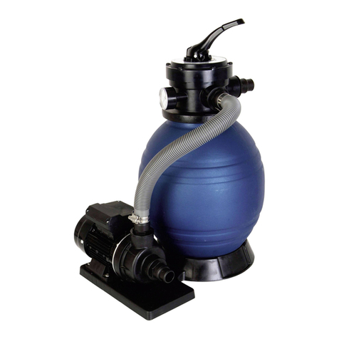
Summer Fun SF-130 Manual

EINBAU-UND BETRIEBSANLEITUNG
INSTALLATION AND MAINTENANCE MANUAL
MANUAL DE INSTALACIÓN Y MANTENIMIENTO
FILTERANLAGE
FILTER SYSTEM
FILTRO MONOBLOC
SF-130
SF-135
SF-140
SF-150
SF-130
SF-135
SF-140
SF-150


-
33
-
SICHERHEITSHINWEISE, BITTE AUFMERKSAM LESEN
Bei der gesamten Installation elektrischer Komponenten muss folgende Norm befolgt werden:
NF
C15-1100
NF
EN
60-3335-22-441
Diese Norm bezieht sich auf "den Aufbau von elektrischen Installationen in Hallenbädern und Freibädern".
Ebenso müssen die Normen befolgt werden, die in jeder Region oder jedem Land anwendbar sind.
Alle Filtereinrichtungen entsprechen der Norm für die Installation C 15-100, die angibt, dass alle elek-
trischen Apparate, die sich in weniger als 3,5 m Entfernung vom Schwimmbad befinden und frei zugän-
glich sind, mit einer Niedrigspannung von 12 V gespeist werden müssen. Alle Apparate, die mit 220 V
gespeist werden, müssen sich mindestens 3,5 m vom Rand des Schwimmbeckens entfernt befinden.
Wenn ein oder mehrere Elemente des Filtersystems geändert werden sollen, muss der Hersteller die
entsprechende Genehmigung erteilen.
Die elektrische Installation muss von Fachleuten für elektrische Installationen durchgeführt werden.
Die Höhe des Sandes darf nicht mehr als 2/3 der Höhe des Tanks betragen.
Lassen Sie den Apparat nicht angeschaltet, wenn Sie das Schwimmbecken benutzen.
Lassen Sie den Apparat nie laufen, ohne ihn vorher korrekt gefüllt zu haben.
Berühren Sie NIE den eingeschalteten Filter, wenn Ihr Körper oder Ihre Hände nass sind.
Immer, wenn Sie am Filter oder dem Ventil arbeiten müssen, UNTERBRECHEN Sie die Stromverbindung.
Vergewissern Sie sich, dass der Boden trocken ist, bevor Sie die elektrische Ausrüstung berühren.
Setzen Sie den Filter nie dort ein, wo er nass werden kann. Das kann zu einem tödlichen Stromschlag führen.
Erlauben Sie nicht, dass sich Kinder oder Erwachsene an den Apparat anlehnen oder auf ihn setzen.
Wenn das flexible Kabel für den Stromanschluss beschädigt ist, muss es ausgetauscht werden. Lesen
Sie aufmerksam die Anweisungen für den Austausch. Im Zweifelsfalle ist der Kundendienst zu befragen.
1 TEILELISTE
Bei dem soeben von Ihnen erstandenen Filter handelt es sich um einen Apparat, der speziell für die
Verwendung bei Aufstellbecken erdacht und hergestellt wurde. Dank seines innovativen Designs und der
großen Funktionsfähigkeit verfügen Sie über die unterschiedlichen Elemente, die für das Filtern von Wasser
erforderlich sind: Filter, Pumpe und Wechselventil in einem einzigen Apparat. Die wichtigsten Teile dieses
Filters sind:
1.1
VORRAUSSETZUNGEN
FÜR
DIE
KORREKTE
INSTALLATION
Die Installation dieser Anlage ist sehr einfach, deshalb kann ein Erwachsener sie in ungefähr 2 STUNDEN
fertigstellen. Dabei müssen die Anleitungen in diesem Handbuch genau befolgt werden.
Folgende Werkzeuge sind für den korrekten Umgang und Einbau der Filterkomponenten notwendig:
FUNKTION WERKZEUG ALTERNATIVES WERKZEUG
Anziehen der Klemmen der Schläuche Schraubendreher 7 mm Schraubendreher Typ Philips
Schutzabdeckung des Kollektor-Rohrs Ein Stück Kunststoff Ein Stück Stoff
DDEEUUTTSSCCHH
ANWEISUNGEN FILTERANLAGE
4-Wege-Ventil
Filterkörper Ø300
Filterpalette
Verbindungsschlauch Ø38
Pumpe "COMPACT 0,4"
Schlauchklemmen
Mutter Ø2 ¼"
Schlauchtülle Ø38
Dichtung
TTEEIILLLLLLIISSTTEE
6-Wege-Ventil
Filterkörper Ø380
Filterpalette
Verbindungsschlauch Ø38
Pumpe "COMPACT 0,6"
Schlauchklemmen
Mutter Ø 2 1/4"
Schlauchtülle Ø38
Dichtung
6-Wege-Ventil
Filterkörper Ø400
Filterpalette
Verbindungsschlauch Ø38
Pumpe "SENA" 3/4HP
Schlauchklemmen
Mutter Ø 2 1/4"
Schlauchtülle Ø38
Dichtung
6-Wege-Ventil
Filterkörper Ø500
Filterpalette
Verbindungsschlauch Ø38
Pumpe "SENA" 1HP
Schlauchklemmen
Mutter Ø 2 1/4"
Schlauchtüllen Ø38
Dichtung
SF-1130
SF-1135
SF-1140
SF-1150

-
44
-
2 VOR ANSCHLUSS DES FILTERS
2.1
LAGE
Das Filter auf einer flachen und festen Unterfläche anbringen, und zwar in einem Abstand von nicht weni-
ger als 3,5 m vom Schwimmbecken entfernt (laut Norm NF C15-100 oder analoger in der jeweiligen Region
oder im jeweiligen Land gültigen Norm) oder auf dem Boden des Schwimmbeckens, um zu vermeiden, dass
in den Reinigungskreislauf Luft eindringt und sich das Filter löst. (Abb. 1). Es ist ratsam, den Filter vor Sonne
und Regen zu schützen und für ausreichende Belüftung zu sorgen, wenn er arbeitet.
2.2
MONTAGE
Nach erfolgter Aufstellung des Filters ist wie folgt vorzugehen:
Beim
Geräteinbau,
bitte
den
beigefügten
Gebrauchtsanweisungen
folgen.
Die Rohröffnung des Behälters innen im Filter mit einem Plastikschutz abdecken, um zu vermeiden, dass
Sand eindringt. (Abb. 2).
Bevor Sie den Behälter mit Sand füllen, achten Sie darauf, dass der Kollektor richtig auf dem Boden sitzt.
Sandfüllmenge: 25kg-SF130, 40kg-SF135, 70kg-SF140, 100kg-SF150.
Das Silikagel hat eine uneingeschränkte Lebensdauer. Es muss nur bei Verlust nachgefüllt werden. Für
zukünftige Nachfüllungen die Einschütthöhe des Silikagels notieren. Der Sack mit dem übriggebliebenen
Sand in einem trockenen Platz aufbewahren. (Abb. 3).
Beseitigen Sie die Sandreste am Filteröffnung und entfernen Sie den Plastikschutz.
Setzen Sie das Wechselventil zusammen mit der Dichtung ein, bringen Sie die Schelle oder den
Verschluss laut den Abbildungen (Abb. 2).
Verbinden Sie jetzt die Ansaug- und Einlaufschläuche mit den entsprechenden Endstücken des Ventils
und befestigen Sie sie mit den Schellen.
Umwickeln Sie die Gewinde des Endstückes des Skimmers mit dem mitgelieferten Teflon und befestigen
Sie mit der Schelle das andere Ende des Ansaugschlauches. Wiederholen sie diesen Vorgang mit dem
Endstück der Rückflußdüse und befestigen Sie den Einlaufschlauch.
Nach der Installierung muß eine erste automatische Reinigung vorgenommen werden. Hierzu ist nach
den Angaben des Absatzes Filterwaschung im Kapitel über die Arbeitsweise vorzugehen 5.3.
3 ELEKTROANSCHLUSS
Bei
der
gesamten
Installation
elektrischer
Komponenten
muss
folgende
Norm
befolgt
werden:
NF
C15-1100
·
NF
EN
60-3335-22-441
Diese
Norm
bezieht
sich
auf
"den
Aufbau
von
elektrischen
Installationen
in
Hallenbädern
und
Freibädern".
Ebenso
müssen
die
Normen
befolgt
werden,
die
in
jeder
Region
oder
jedem
Land
anwendbar
sind.
Die Pumpe muß an einen 220/230 V 50 Hz Wechselstromanschluß mit Erdung angeschlossen werden.
Verbrauch 240 W.
Es muß unbedingt ein Allpolschalter verwendet werden, damit der Filter bei Nichtbenutzung vom Strom
abgeschaltet werden kann. Außerdem ist ein 30 mA Differential gegen Elektroschläge zu verwenden.
(Gehört nicht zum Lieferumfang und kann im Elektrohandel erworben werden).
4 OBERES VENTIL
Das obere Ventil übernimmt die Auswahl der 4 unterschiedlichen Funktionen des Filters: Waschen des
Silikagels (backwash), Filtern (filter), Entleeren (waste), und Schließen (closed) - SF 130.
Das obere Ventil übernimmt die Auswahl der 6 unterschiedlichen Funktionen des Filters: Waschen des
Silikagels (backwash), Zirkulieren (recirculation), Spülen (rinse), Filtern (filter), Entleeren (waste), und
Schließen (closed) - SF135, SF140, SF150.
Stellung
des
Ventils
zu
verändern,
muss
wie
folgt
vorgegangen
werden
bei
SF130:
Der Stecker muß immer herausgezogen werden.
Der obere dreieckige Knof des Ventils ist zu lockern, bis es möglich ist, den Deckel anzuheben und zu drehen.
Der Deckel wird gedreht, bis die gewünschte Funktion mit dem Ausstoßventil übereinstimmt und die Rippe einrastet.

-
55
-
Der Knopf wird wieder nicht zu fest angedrückt, damit die Elemente im Inneren des Ventils keinen
Schaden erleiden.
Stellung
des
Ventils
zu
verändern,
muss
wie
folgt
vorgegangen
werden
bei
SF135,
SF140,
SF150:
Der Stecker ist immer aus der Leitung zu ziehen.
Um die Gegenkraft der Innenfeder zu bezwingen und die vordere Rippe aus ihrem Aufnahmebett sprin-
gen zu lassen, wird der obere Griff solange fest gedrückt, bis er sich um sich selbst drehen läßt.
Der Griff wird leicht gedreht, bis die vordere Rippe mit dem Aufnahmebett für den gewünschten Vorgang
übereinstimmt.
Der Griff wird langsam losgelassen, wobei man nachprüft, ob die vordere Rippe gut in ihr Aufnahmebett
eingerastet ist liegt.
5 ARBEITSWEISE
DAS
CHEMISCHE
PRODUKT
DARF
NIEMALS
IN
DEN
KORB
ODER
DURCH
DIE
SCHWÄMME
ODER
DIE
KARTUSCHE
EINGEGEBEN
WERDEN.
DADURCH
WIRD
DAS
MATERIAL
DES
APPARATES
ZERSTÖRT
UND
SEINE
LEISTUNG
BEEINTRÄCHTIGT.
Die Arbeitsweise dieses Filters basiert auf der Filterkapazität des Silikagels, das sich in seinem Inneren
befindet. Das Wasser aus dem Schwimmbecken wird von der Filterpumpe ausgestossen und durch das
Silikagel gedrückt, wobei die Verschmutzung des Wassers im Sand, der wie ein Filterelement arbeitet,
zurückgehalten wird. Das Umfeld, Bäume, Blütenstaub, Insekten und Badefrequenz sind unter anderem
Faktoren, die die Verunreinigung des Wassers bestimmen. Das Silikagel muß daher mehr oder weniger oft
gereinigt werden (siehe hierzu den Abschnitt automatischer Reinigungsvorgang).
Um das Wasser im Schwimmbecken in gutem Zustand zu halten, müssen außerdem die vom Hersteller
empfohlenen chemischen Produkte verwendet werden (Chlor, Algenschutzmittel, Flockungsmittel, u.s.w.).
5.1
FILTERFÜLLUNG
Es ist unbedingt erforderlich, daß der Filter immer korrekt gefüllt ist. Wenn der Filter nicht gefüllt ist, kann
sich in seinem Inneren eine Luftkammer bilden, die einen defekten Umlauf des Wassers bewirkt. Das
macht ein korrektes Filtern durch das Silikagel unmöglich und schadet dem Motor.
Der Filter kann sich aus folgenden Gründen leeren:
Inbetriebnahme einer neuen Anlage.
Inbetriebnahme einer Anlage,die während eines längeren Zeitraums nicht benutzt wurde.
Nach einer Reinigung des Bodens durch einen Bodensauger.
Luftansaugung über den Skimmer aufgrund eines zu niedrigen Wasserspiegels im Schwimmbecken.
Durch eine falsche Benutzung der Anlage, den Ansaugdeckel oder Skimmerstopfen.
5.2
FILTRIEREN
NIEMALS
AN
EINEM
VENTIL
ARBEITEN,
WENN
DER
MOTOR
LÄUFT.
Vor dem Filtern das Silikagel reinigen; dafür das Ventil in Position “Waschen” stellen (Absatz 5.3).
Danach muss das Ventil zurück auf der Position Filtern (FILTER) und dort stehen. Die Lebensdauer des
Filters wird verlängert, wenn er nicht länger als 4 Stunden hintereinander arbeitet. Ihr täglicher Filterbedarf
richtet sich nach den m3Wasservolumen in Ihrem Beckeu in bezug auf die m3/h Durchflussmenge des
Filters. Lassen Sie den Motor nach einer Laufzeit von 4 h mindestens 2 h ruhen.
Volumen im Schimmbad in m3= notwendige Stunden
Filterdurchflussmenge m3
Beispiel: 42 m 3=7,63 Stunden 2 Zyklen von 4 Stunde mit einem Zwischenzyklus von 2 Stunden Pause
5,5 m3/h
Beim ersten Filtervorgang müssen die angegebenen Ruhepausen eingehalten werden.

-
66
-
5.3
REINIGUNG
DES
SILIKAGELS
Bei der Reinigung des Filters muss das Silikagel im Inneren des Filters gereinigt werden. Hierfür wird mit dem
oberen Wechselventil die Laufrichtung des Wassers umgedreht. Diese Reinigung sollte regelmässig durchge-
führt werden. Dabei ist auf einige Faktoren zu achten, die anzeigen, wenn das Silikagel verschmutzt ist:
Der Rückfluss ist vermindert, obwohl überprüft wurde, dass die Pumpe gefüllt ist.
Das Manometer zeigt einen zu hohen Druck an (die Nadel steht zwischen Gelb und Rot oder auf Rot)).
5.4
ENTLEEREN
DES
SWIMMINGPOOLS
Der Filter ermöglicht es, den Swimmingpool nach Beendigung der Badesaison fast vollständig zu entleeren.
Hierfür muss das obere Wahlventil auf Position Entleeren (waste) (Abb. 5) gestellt werden. Bei noch nicht
angestelltem Filter wird der Schlauch ø 38 mm x 1,5 m an die Wasserentleerung (waste) des Ventils anges-
chlossen und sein anderes Ende zu einem Wasserabfluss oder zur Kanalisation geführt.
5.5
REINIGUNG
DES
SWIMMINGPOOLBODENS
Zur Reinigung des Schwimmbeckenbodens kann die Filterpumpe mit einem Bodenreiniger verwendet werden:
Man benötigt außerdem einen Schlauch ø38 mm und einen Teleskopstange. Fragen Sie in Ihrem Geschäft
nach, oder beim Kundendienst des Schwimmbeckenherstellers. Verwenden Sie immer Originalersatzteile.
Wenn der Schlauch länger als erforderlich zum Erreichen sämtlicher Stellen im Schwimmbecken ist, wird
seine Handhabung schwierig. Schneiden Sie das überflüssiger Schlauchende ab. Achten Sie darauf, daß
die Gummienden nicht undicht werden.
5.6
SPÜLEN
SF130,
SF135,
SF140,
SF150
Nach dem "REINIGEN" des Filters und nachdem die Anlage auf Position "FILTERN" gestellt wurde, läuft das
Wasser einige Sekunden lang trüb zum Schwimmbad. Um zu vermeiden, dass dieses trübe Wasser in das
Schwimmbad gelangt, gibt es diese Position "SPÜLEN" am Mehrwegventil. Wie folgt vorgehen: Sofort nach
dem "REINIGEN" das Mehrwegventil auf Position "SPÜLEN" (Abb.5) stellen und die Pumpe 1 Minute lang
einschalten. Dann die Pumpe abschalten und das Ventil auf "FILTERN" stellen.
5.7
ZIRKULIEREN
SF135,
SF140,
SF150
In dieser Position des Wahlventils wird das Wasser von der Pumpe direkt ins Schwimmbad geleitet, ohne
durch das Innere des Filters geleitet zu werden (Abb.5).
5.8
GESCHLOSSEN
Das Wechselventil steht auf der Stellung Verschluß (CLOSED). Diese wird verwendet, um zu vermeiden, daß
das Wasser durch die Schläuche und den Filter zirkuliert (Abb.5).
6 WARTUNG
Nach Beendigung der Badesaison muß der Filter an einem trockenen, wettergeschützten Platz aufbewahrt werden.
Aus diesem Grund werden nach Durchführung eines automatischen Reinigungsvorganges des Silikagels
die Schläuche abmontiert und das gesamte Wasser über den Entleerungsdeckel des Depots aus dem Filter
ausgelassen.
Nachdem das gesamte Wasser aus dem Filter entfernt worden ist, wird sorgfältig die Filteröffnungsgewinde
von Silikagelresten gesäubert, bevor der Deckel erneut aufgesetzt wird, denn das Siikagel könnte die
Filteröffnungsgewinde beschädigen.
Der Entleerungsstopfen des Filterkessels darf nur für diesen Vorgang verwendet werden.
SEHR
WICHTIG: Bevor der Filter nach einer längeren Ruhepause wieder in Betrieb genommen wird, ist zu über-
prüfen, ob sich die Achse des Motors nicht festgeklemmt hat. Entfernen Sie das Schutzgehäuse wie im beschrie-
ben, indem sie es mit einem flachen Schraubenzieher von dem Ende her bewegen, das über dem Metalldeckel
der Lüftung hinter der Motorwicklung erscheint, bis es frei ist. Bewegen Sie danach die Achse nach rechts und
links. Sollte sie sich nicht drehen lassen, müssen Sie das Laufrad der Turbine reinigen.
Nach einem längeren Stillstand empfiehlt es sich ebenfalls, zu überprüfen, ob die Pumpe gefüllt ist, bevor
er angestellt wird.

-
77
-
1 PACKAGING COMPONENTS
The filter which you have just purchased is a device which is especially planned and designed for above
ground pools. As a result of its innovative design and high level of functionality, it provides you with the dif-
ferent components required to filter water: filter, pump and selector valve in a single unit. The main compo-
nents of this filter are as follows:
EENNGGLLIISSHH
MONOBLOC FILTER INSTRUCTIONS
SAFETY INSTRUCTIONS. READ CAREFULLY
All electrical installations should comply with the following standard:
NF
C15-1100
NF
EN
60-3335-22-441
that refers "to the construction of electrical installations, both in indoor and outdoor swimming pools",
or the equivalent standard in force in each region or country.
All filtering should follow the C 15-100 installation standard that stipulates that all electrical apparatus
located at less than 3.5 m. from the pool and freely accessible, should be supplied by a very low volta-
ge of 12 V. All apparatus supplied with 220 V should be located at least 3.5 m. from the swimming pool
edge. Ask the manufacturer for permission to make any modifications in one or more elements of the
filtering system.
The electrical installation should be performed by professional staff qualified in electrical installations.
The height of the sand should not exceed 2/3 of the height of the tank.
The apparatus must not be on while the pool is being used.
Do not operate the apparatus unless it is properly primed.
NEVER touch the filter when it is operating if you are wet or have wet hands.
When handling the filter or valve, DISCONNECT the power supply.
Make sure that the ground is dry before touching the electrical equipment.
Do not install the filter where it could become wet, as it may cause electrocution.
Do not allow children or adults to lean against or sit on the apparatus.
If the supply flex of the apparatus is damaged, it should be replaced. Read the instructions carefully to
replace it. If in doubt, contact the technical service.
1.1
REQUIREMENTS
FOR
CORRECT
INSTALLATION
This filtration system is easy to install and can be assembled by ONE ADULT in less than 2 HOURS, taking
care to correctly follow the instructions detailed in this manual.
Only the following tools are required to correctly handle the filter components and to install it.
TASK TOOL ALTERNATIVE TOOL
Tighten the hose flanges 7mm Stecker screwdriver Philips screwdriver
Protection of collector pipe Piece of plastic Piece of fabric
4 way valve
Filter body Ø300
Filter base
Connection hose Ø38
Pump "COMPACT 0,4"
Hose clamps
Nut Ø 2 ¼"
Discharge sleeve Ø38
O-Ring
CCOOMMPPOONNEENNTTSS
4 way valve
Filter body Ø380
Filter base
Connection hose Ø38
Pump "COMPACT 0,6"
Hose clamps
Nut Ø 2 1/4"
Discharge sleeve Ø38
O-Ring
4 way valve
Filter body Ø400
Filter base
Connection hose Ø38
Pump "SENA 3/4HP."
Hose clamps
Nut Ø 2 1/4"
Discharge sleeve Ø38
O-Ring
4 way valve
Filter body Ø500
Filter base
Connection hose Ø38
Pump "SENA 1HP."
Hose clamps
Nut Ø 2 1/4"
Discharge sleeve Ø38
O-Ring
SF-1130
SF-1135
SF-1140
SF-1150

-
88
-
2 BEFORE CONNECTING THE FILTER
2.1
LOCATION
Place the filter on a flat, solid surface at a minimum distance of 3.5 metres from the pool , Fig. 1 (in accor-
dance with standard NF C15-100 or the equivalent standard of the region or country) and at the same level
as the bottom of the pool to prevent air from entering the cleansing circuit and the filter from becoming
unprimed. The filter should be protected from sun and rain, and kept it in an area with sufficient ventilation
during operation. Never cover it during operation.
2.2
ASSEMBLY
After the filter has been set into place, proceed as follows:
You will find instruction sheets with the equipment which show you the steps to follow when starting to
assemble the equipment
Before putting in sand, place the inner collector properly centered on the bottom of the filter (Fig. 2).
Sand filling: 25kg-SF130, 40kg-SF135, 70kg-SF140, 100kg-SF150.
The silica sand lasts for an unlimited period of time and should only be replaced in the event of sand loss.
Record the sand level for future replacement. Keep the remaining sand in the bag in a dry place. (Fig.3).
Eliminate the remains of sand from the filter opening and remove the protective plastic.
Place the TOP selector valve with its coupling and secure with the plastic band or seal following the dia-
grams in the instructions attached to the metal plastic.
Tighten firmly the screw on the plastic band (Fig.2 ), which joins the valve to the filter.
Cover the opening of the inner collector tube with protective plastic in order to prevent sand from entering the tube.
Connect the suction and discharge hoses to the suction and discharge terminals on the valve, tightening
them firmly with the clamps.
Insert the Teflon supplied on the thread of the skimmer terminal and connect the other end of the suc-
tion hose. Tighten firmly with a clamp. Repeat the same procedure with the feedback nozzle terminal and
connect the discharge hose.
Following installation, the first cycle of filter backwash should be performed. In order to do so, follow the
instructions in the section 5.3.
3
ELECTRIC
CONNECTION
All
electrical
installations
should
comply
with
the
following
standard:
NF
C15-1100
·
NF
EN
60-3335-22-441
that
refers
"to
the
construction
of
electrical
installations,
both
in
indoor
and
outdoor
swimming
pools",
or
the
equivalent
standard
in
force
in
each
region
or
country.
The pump must be connected to a 220/230 V. alternating current and 50 Hz power point, with earth con-
nection. Consumption: 240 W.
An omnipolar switch must be used to ensure there is no power feed to the filter when it is not in use. A 30
mA differential must also be used to protect from electrical breakdowns. (Not supplied. These items can be
purchased at electricity shops.)
4 TOP SELECTOR VALVE
The selector valve is responsible for selecting the 4 different filter functions: backwash, filter, waste, and
close for the model SF130.
The selector valve is responsible for selecting the 6 different filter functions: backwash, recirculation, rinse,
filter, waste, and close for the models SF135, SF140, SF150.
To
change
the
valve
setting,
proceed
as
follows
for
model
SF130
Always disconnect the socket.
Loosen the upper triangular knob on the valve until you can lift the cover of the housing and turn it.
Rotate the cover until the desired setting is aligned with the discharge hose and the rib is inserted in its housing.
Retighten the knob, but be careful not to overtighten as the internal components of the valve may be damaged.

-
99
-
To
change
the
valve
setting,
proceed
as
follows
for
models
SF135,
SF140,
SF150
Always disconnect the power socket.
Press firmly on the upper valve control until the front rib is released from its housing and it can turn on
its own axis.
Gently turn the control until the front rib is aligned with the housing for the desired operation.
Release the control gradually and check that the front rib is fully inserted in the appropriate housing.
5 OPERATION
The operation of this filter is based on the filtration capacity of the silica sand which is inside. The water in
the pool is driven by the filter pump and forced to pass through the silica sand. The sand acts as a filtering
element which retains the impurities in the water. The environment, trees, pollen, insects and frequency of
bathing, as well as other factors, determine the dirtiness of the water in the pool. Depending on the dirti-
ness, the silica sand in the filter should be cleaned with greater or less frequency.
To maintain the pool water in good condition, use the chemical products recommended by the manufactu-
rer (chlorine, alga protection, flocculant etc.).,
THE
CHEMICAL
PRODUCT
SHOULD
NEVER
BE
PLACED
IN
THE
BASKET
OR
THROUGH
THE
FILTER,
THIS
WOULD
DETERIORATE
THE
MATERIALS
OF
THE
UNIT
AND
LIMIT
ITS
EFFICACY.
5.1
PRIMING
THE
FILTER
The filter must be correctly primed at all times. If the filter is not primed this means that an air chamber has
been created inside which causes defective circulation of water. This fact prevents proper filtration of the
water by the silica sand and is detrimental to the motor.
The filter may become unprimed for several reasons:
Starting up a new unit.
Starting up a unit after an extended period of inactivity.
Following use of a suction bottom cleaner.
Air absorbed by the skimmer due to the low level of water in the pool.
Due to incorrect use of the unit, suction cover or skimmer plug.
5.2
FILTRATION
NEVER
HANDLE
THE
VALVE
WHILE
THE
MOTOR
IS
RUNNING
Before the first filtration operation, perform a backwash of the sand. (Section 5.3)
The valve must be on the filtration setting. The service life of the filter will be longer if the periods of con-
tinuous operation do not exceed 4 hours. The need for daily filtration is determined by the volume of
water in the pool in m3in comparison to the m3/h filter flow rate for a water temperature of around 21ºC
and placed at 3.5 m. from the pool. Leave the motor at off for at least 2 h. between each 4 h period of
operation.
Volume of the pool in m3 = hours required
Filter flow in m3/hr.
Example:
42 m3=7.63 hours 2 cycles of 4 hours with an intermediary cycle of 2 hours rest
5.5 m3/h
In the initial filtration treatment it is important to leave the filter off for the time indicated. It is recommen-
ded to increase the filtration time the higher the water temperature of the pool.
5.3
SAND
FILTER
BACKWASH
The backwash process cleans the silica sand from inside the filter. This process should be done regularly.
For this purpose you should observe several factors which indicate the dirtiness of the sand:
Decrease in the flow rate of feedback is detected, after checking that the pump is well primed.
Pressure gauge indicates that there is excess pressure (needle pointing between yellow and red, or on red).

-
1100
-
5.4
DRAINING
THE
SWIMMING
POOL
The filter allows you to drain the pool almost completely after the bathing season has ended. To do so, place
the upper selector valve on the waste setting Fig 5. Before plugging in the filter, connect the ø38 mm x 1.5
m hose to the valve waste outlet and point the other end of the hose towards a drain or sewer.
5.5
CLEANING
THE
POOL
BOTTOM
In order to clean the pool bottom, use the pump filter with one suction cleaner.
You will also need a ø38 mm hose and the pole. To purchase these items, consult your establishment or
ask the After-Sales Service provided by the pool manufacturer. Always use original replacement parts.
A hose which extends beyond the length required to reach all points of the pool is more difficult to use. Cut
off the section of the hose which is not needed. Check that the rubber terminals conserve their seal.
5.6
RINSING
IN
MODELS
SF130,
SF135,
SF140,
SF150
After "WASHING" the filter and placing the installation in the "FILTERING" position, the water flowing to the
pool will be cloudy for a few seconds. To avoid this cloudy water from circulating in the swimming pool, the
"RINSING" operation should be performed as follows. Immediately after "WASHING", stop the pump, place
the selector valve in the "RINSING" Fig 5,position and connect the pump for 1 minute. After this time, stop
the pump and place the valve in the "FILTERING" position.
5.7
RECIRCULATION
IN
MODELS
SF135,
SF140,
SF150
In this position the selector valve allows the water from the pump to go directly to the swimming pool without
passing through the inside of the filter Fig 5.
5.8
CLOSED
The CLOSED setting of the selector valve is used to prevent water from circulating through the hoses and
the filter Fig 5.
6 MAINTENANCE
After the bathing season has ended, the filter should be kept in a dry place where it is protected from incle-
ment weather. For this purpose, after performing a final backwash to clean the silica sand, dismount the
hoses and drain the water in the filter through the tank drain plug until it is completely empty.
After removing all of the water from the filter, carefully clean the remains of silica sand from the thread befo-
re replacing the plug. Failure to do so could damage the thread.
The filter tank drain plug should only be used in this operation.
VERY
IMPORTANT: Following an extended period of inactivity, before starting up the filter check that the
drive shaft is not jammed. Remove the protective housing. After winding the motor, use a flat screwdriver to
move it by the end which is visible through the metal ventilation cover, until it is released and the shaft turns
to the right and the left. If it does not turn, clean the wheel of the turbine..
After stoppage for an extended period, it is also recommendable to make sure that the filter is primed befo-
re starting up.

-
1111
-
1 COMPONENTES EMBALAJE
El filtro que acaba usted de comprar es un aparato especialmente concebido y diseñado para piscinas ele-
vadas. Con un innovador diseño y una gran funcionalidad, dispone usted de los diferentes elementos nece-
sarios para filtrar el agua: Filtro, bomba y válvula selectora en un mismo aparato. Los principales compo-
nentes de este filtro son:
EESSPPAAÑÑOOLL
INSTRUCCIONES FILTRO MONOBLOC
INDICACIONES DE SEGURIDAD, LEALAS ATENTAMENTE
En todo lo referente a la instalación eléctrica debe seguirse la normativa:
NF
C15-1100
NF
EN
60-3335-22-441
que hace referencia "a la construcción de instalaciones eléctricas, tanto en piscinas cubiertas como en
piscinas al aire libre", o la normativa análoga vigente en cada zona o país.
Todas las filtraciones siguen la norma de instalación C 15-100 que especifica que todo aparato eléctri-
co ubicado a menos de 3,5 m de la piscina y accesible libremente debe estar alimentado con una ten-
sión muy baja (12 V). Todo aparato alimentado en 220 V debe estar ubicado por lo menos a 3,5 m del
borde de la piscina. Pedir permiso del fabricante para toda modificación de uno o varios elementos del
sistema de filtración.
La instalación eléctrica debe ser hecha por personal profesional cualificado en instalaciones eléctricas.
La altura de la arena no debe sobrepasar los 2/3 de la altura del depósito.
No tenga el aparato en marcha mientras utiliza la piscina.
No haga funcionar el aparato sin estar correctamente cebado.
No toque NUNCA el filtro en marcha con el cuerpo húmedo o las manos húmedas.
Siempre que deba manipular el filtro o la válvula, DESCONÉCTELO de la toma de corriente.
Asegúrese de que el suelo está seco antes de tocar el equipo eléctrico.
No coloque el filtro donde pueda mojarse, puede causar electrocución.
No permita ni a niños ni a adultos apoyarse o sentarse sobre el aparato.
Si el cable flexible de alimentación de este aparato está dañado, debe ser sustituido. Lea detenidamen-
te las instrucciones para su sustitución. Ante la duda consulte con un servicio técnico.
1.1
NECESIDADES
PARA
UNA
CORRECTA
INSTALACIÓN
Por su facilidad de instalación este equipo puede ser montado por UNA PERSONA ADULTA y en un período
de tiempo de alrededor de 2 HORAS, con la precaución en todo momento de hacer un correcto seguimien-
to de las instrucciones detalladas en este manual.
Para una manipulación correcta de los componentes del filtro y su correcta instalación son necesarias las
siguientes herramientas:
FUNCIÓN HERRAMIENTA HERRAMIENTA
ALTERNATIVA
Apretar las bridas de las mangueras Destornillador stecker 7mm Destornillador boca philips
Protección del tubo del colector Trozo de plástico Trozo de tela
Válvula de 4 vías
Cuerpo filtro Ø300
Base monobloc
Manguera conexión Ø38
Bomba "COMPACT 0,4"
Abrazaderas
Tuerca Ø 2 ¼"
Conexión espiga Ø 38
Junta torica
DDEENNOOMMIINNAACCIIOONN
Válvula de 6 vías
Cuerpo filtro Ø380
Base monobloc
Manguera conexión Ø38
Bomba "COMPACT 0,6"
Abrazaderas
Tuerca Ø 2 1/4"
Conexión espiga Ø38
Junta torica
Válvula de 6 vías
Cuerpo filtro Ø400
Base monobloc
Manguera conexión Ø38
Bomba "SENA 3/4 CV"
Abrazaderas
Tuerca Ø 2 1/4"
Conexión espiga Ø38
Junta torica
Válvula de 6 vías
Cuerpo filtro Ø500
Base monobloc
Manguera conexión Ø38
Bomba "SENA 1CV"
Abrazaderas
Tuerca Ø 2 1/4"
Conexión espiga Ø38
Junta torica
SF-1130
SF-1135
SF-1140
SF-1150

-
1122
-
2 ANTES DE CONECTAR EL FILTRO
2.1
SITUACIÓN
Colocar el filtro a a una distancia no inferior a 3,5 metros de la piscina, Fig.1 (por seguridad eléctrica) y al
mismo nivel del fondo de la piscina para evitar que en el circuito de depuración entre aire y el filtro se des-
cebe. Es conveniente resguardar el filtro del sol y la lluvia, y mantenerlo con una ventilación suficiente
durante su funcionamiento.
2.2
MONTAJE
Una vez situado el filtro, proceder como sigue:
Seguir
las
indicaciones
de
las
hojas
suministradas
con
el
equipo
en
la
que
se
indican
los
pasos
iniciales
para
el
montaje
del
equipo.
Antes de introducir la arena, asentar correctamente el colector interior en el fondo del filtro, Fig.2.
Introducir en el interior del filtro la arena: 25 Kg-SF130, 40 Kg-SF135, 70 Kg-SF140, 100Kg-SF150.
La arena de sílex tiene una duración ilimitada. Sólo debe reponerse en caso de pérdida. Tome la referen-
cia del nivel de arena de sílex para reposiciones futuras, Fig.3.
Eliminar los restos de arena de la boca del filtro y retirar el plástico protector.
Vuelva a colocar la válvula selectora TOP con su junta y colocar el zuncho o cierre.
Apretar fuertemente el tornillo del zuncho que sujeta la válvula al filtro, Fig.2.
Proceda a conectar en los terminales de aspiración y de impulsión de la válvula las mangueras de aspi-
ración y de impulsión, fijandolas fuertemente con las abrazaderas.
Proceda a poner en la rosca del terminal del skimmer el teflón suministrado y conecte el otro extremo
de la manguera de aspiración apretando fuertemente con una abrazadera, repita la operación con el ter-
minal de la boquilla de retorno y conecte la manguera de impulsión.
Una vez instalado, deberemos efectuar un primer ciclo de lavado del filtro, para ello seguiremos lo des-
crito en el apartado 5.3
3 CONEXIÓN ELÉCTRICA
En
todo
lo
referente
a
la
instalación
eléctrica
debe
seguirse
la
normativa:
NF
C15-1100
/
NF
EN
60-3335-22-441
que
hace
referencia
"a
la
construcción
de
instalaciones
eléctricas,
tanto
en
piscinas
cubiertas
como
en
piscinas
al
aire
libre",
o
la
normativa
análoga
en
cada
zona
o
país.
La bomba se debe conectar a una toma de tensión de 220/230 V de corriente alterna y 50 Hz, con cone-
xión a tierra. Consumo 240 W.
Es imprescindible utilizar un interruptor omnipolar para dejar sin tensión el filtro cuando no lo esté utiliza-
do y un diferencial de 30 mA. para protección de descargas. (No suministrado. Puede adquirirse en esta-
blecimientos de electrícidad.).
4 VÁLVULA SELECTORA SUPERIOR
La válvula selectora superior del filtro es la encargada de seleccionar las 4 diferentes funciones del filtro:
filtración (filter), lavado (backwash), vaciado (waste) y cerrado (closed) en el modelo SF130.
La válvula selectora superior del filtro es la encargada de seleccionar las 6 diferentes funciones del filtro:
filtración (filter), lavado (backwash), recirculación (recirculate), enjuague (rinse), vaciado (waste) y cerrado
(closed) en los modelos SF135, SF140, SF150.
Para variar la posición de la válvula, proceder como sigue para el modelo SF130:
Desconectar siempre el enchufe.
Aflojar el pomo triangular superior de la válvula hasta que nos permita levantar la tapa de su alojamien-
to y girarla.
Girar la tapa hasta que la operación deseada esté alineada con la manguera de impulsión y el nervio
quede encajado en su alojamiento.
Apretar el pomo de nuevo, no excesivamente, se pueden dañar elementos internos de la válvula.

-
1133
-
Para variar la posición de la válvula, proceder como sigue para los modelos SF135, SF140, SF150.
Desconectar siempre el enchufe.
Presionar firmemente el mando superior de la válvula desencajando el nervio delantero de su alojamien-
to, hasta que nos permita girar sobre sí mismo.
Girar suavemente el mando hasta alinear el nervio delantero con el alojamiento de la operación deseada.
Soltar el mando sin brusquedad, comprobando que el nervio delantero queda bien encajado en su alo-
jamiento.
5 FUNCIONAMIENTO
El funcionamiento de este filtro se basa en la capacidad de filtrado de la arena de sílex que hay en su inte-
rior. El agua de la piscina es impulsada por la bomba del filtro y forzada a pasar a través de la arena de
sílex, quedando retenidas las impurezas del agua en al arena que actúa de elemento filtrante. El ambien-
te, árboles, polen, insectos y frecuencia de baños, son entre otros, los factores que determinan la suciedad
del agua de la piscina, se deberá limpiar la arena de sílex del filtro con mayor o menor frecuencia.
Para mantener en buen estado el agua de la piscina debemos además utilizar los productos químicos acon-
sejados por el fabricante (cloro, antialgas, floculante, etc.).
EN NINGÚN CASO EL PRODUCTO QUÍMICO DEBE PONERSE EN EL CESTO O A TRAVÉS DEL FILTRO, ELLO
DETERIORARÍA LOS MATERIALES DEL APARATO Y LIMITARÍA SU EFICACIA.
5.1
CEBADO
DEL
FILTRO
Es imprescindible que el filtro se encuentre en todo momento correctamente cebado. Que el filtro no este
cebado significa que en su interior se ha creado una cámara de aire que provoca una circulación defectuo-
sa del agua, este hecho impide el correcto filtraje de la misma por parte de la arena de sílex y perjudica al
motor.
El filtro puede descebarse por varios motivos:
Puesta en marcha de un equipo nuevo.
Puesta en marcha de un equipo tras un período largo de falta de utilización.
Tras utilizar un limpiafondos de aspiración.
Absorción de aire por el skimmer debido a un nivel bajo en el agua de la piscina.
Por una incorrecta utilización del equipo, tapa de aspiración o tapón de skimmer.
5.2
FILTRACIÓN
NO MANIPULAR EN NINGÚN CASO LA VÁLVULA CON EL MOTOR EN MARCHA
Previo a la filtración inicial realizar un lavado de la arena. (Apartado 5.3)
La válvula debe estar en posición de filtrado (FILTER). La vida útil del filtro se alarga con períodos de fun-
cionamiento continuado no superiores a 4 h. Sus necesidades de filtración diarias vienen determinadas
por el volumen en m3de agua de su piscina en relación a los m3/h de caudal del filtro para una tempera-
tura del agua de 21ºC aproximadamente y colocado a 3,5 m de su piscina. Deje al menos 2 h. de reposo
al motor entre cada período de funcionamiento de 4 h.
Volumen piscina en m3=horas necesarias
Caudal filtro en m3/h
Ejemplo:
42 m 3 =7,63 horas 2 ciclos de 4 horas con un ciclo intermedio de 2 horas de descanso
5,5 m3/h
En el tratamiento inicial de filtración debe respetar los períodos de reposo indicados. Se recomienda
aumentar el tiempo de filtración cuanto mayor sea la temperatura del agua de su piscina.

-
1144
-
5.3
LAVADO
DEL
FILTRO
Con el proceso de autolavado procedemos a limpiar la arena de sílex del interior del filtro, para ello se invier-
te el sentido de circulación del agua mediante la válvula selectora superior. Este proceso debe hacerse con
regularidad, para ello se debe estar atento a varios factores que determinan que la arena está sucia:
Que se detecte una disminución del caudal de retorno, una vez comprobado que la bomba está bien cebada.
Que el manómetro nos indique una presión excesiva (aguja indicando entre amarillo y rojo, o sobre rojo).
5.4
VACIADO
DE
LA
PISCINA
El filtro le permite vaciar casi totalmente la piscina una vez terminada la temporada de baño. Para ello debe-
rá poner la válvula selectora superior en posición de desagüe (waste) Fig.5., sin enchufar el filtro todavía,
conectar la manguera de ø 38 mm x 1,5 m a la salida de desagüe (waste) de la válvula y dirigir el otro extre-
mo de la manguera a un desagüe o alcantarilla.
5.5
LIMPIEZA
DEL
FONDO
DE
LA
PISCINA
Para la limpieza del fondo de la piscina, puede aprovechar la bomba del filtro, con un Limpiafondos. También
precisará la manguera de ø38 mm y la pértiga. Consulte en su establecimiento o con el Servicio Postventa del
fabricante de la piscina para su adquisición. Utilice siempre recambios originales.
Una longitud de manguera mayor a la necesaria para llegar a todos los puntos de la piscina dificulta su uso.
Recorte el tramo de manguera que le sobre. Vigile que por los terminales de goma no pierda su estanqueidad.
5.6
ENJUAGUE
EN
MODELOS
SF130,
SF135,
SF140,
SF150
Después de haber realizado un "LAVADO" del filtro y poner la instalación en posición de "FILTRACIÓN", el agua
durante unos segundos afluye a la piscina de color turbio, con el fin de evitar que esta agua turbia circule a
la piscina existe esta posición de la válvula selectora "ENJUAGUE", operar como sigue: Inmediatamente des-
pués del "LAVADO", parar la bomba, situar la válvula en posición de "ENJUAGUE" Fig.5.y conectar la bomba
durante 1 minuto, transcurrido éste parar la bomba y situar la válvula en "FILTRACIÓN".
5.7
RECIRCULACIÓN
EN
MODELOS
SF135,
SF140,
SF150
En esta posición la válvula selectora efectúa el paso del agua procedente de la bomba directamente a la
piscina, sin pasar por el interior del filtro. Fig.5.
5.8
CIERRE
La posición de la válvula selectora cerrado (CLOSED) se utiliza para evitar la circulación del agua a través
de las mangueras y del filtro. Fig.5.
6 MANTENIMIENTO
Una vez terminada la temporada de baño se deberá guardar el filtro en lugar seco y protegido de la intem-
perie.
Por este motivo y tras haber hecho un autolavado final para dejar limpia la arena de sílex, se desmontarán
las mangueras y se vaciará totalmente de agua el filtro a través del tapón de vaciado del deposito.
Una vez expulsada toda el agua del filtro, limpiar cuidadosamente la rosca de residuos de arena de sílex
antes de volver a colocar el tapón, podrían inutilizar la rosca.
El tapón de vaciado del depósito filtro solo debe ser usado en esta operación.
MUY
IMPORTANTE: Antes de poner el filtro en funcionamiento tras un largo período de inactividad, com-
pruebe, que el eje del motor no se encuentra agarrotado. Quite la carcasa de protección, moviendolo con
un destornillador plano, por el extremo que aparece a través de la tapa metálica de ventilación, tras el bobi-
nado del motor, hasta que se libere y gire el eje a derecha e izquierda. Si no gira, proceda a la limpieza del
rodete de la turbina como se indica en el apartado. Es conveniente, asimismo, asegurarse que el filtro está
cebado antes de un arranque tras una parada continuada.

-1155
-
SF-1135
/
SF-1140
/
SF-1150
SF-1130
FIG.1
FIG.3
FIG.4
=
25
Kg.
SF-1130
=
40
Kg.
SF-1135
=
70
Kg.
SF-1140
=
100
Kg.
SF-1150
FIG.2
SF-1150
SF-1130
SF-1135
SF-1140

-
1166
-
FIG.5
SF-1130 SF-1135
SF-1140
SF-1150
MOD.: SF-1130
SF-1135
COMPACT
PUMP
MOD.: SF-1140
SF-1150
SENA
PUMP

-
1177
-
SF-1130
Nº
1
2
3
4
5
7
8
9
10
11
6
Beschreibung
4 Wege Ventil
Kunststoff Klemmring Set
Dichtung Ventil
Filterstern Set Ø300
Filterkörper Ø300 blau
Entlüftungsstopfen 3/8"
Dichtung Entlüftungsstopfen
Filterpalette
Pumpe COMPACT 04
Schlauchklemmen Edelstahl
Verbindungsschlauch Ø38
Manometer Set 1,6 BARS
ART.NR.
09092
08006R1003
720R1750057
08006R1000
08006R0001A
32814R0001
00541R0405
09080R0001
25470-1190
08007R0001
09081R0002
09090R2000
Description
4 Way valve
Plastic clamp set
"O" Ring valve
Collector set Ø300
Filter body Ø300 blue
Sand purge plug 3/8"
O-Ring for purge plug
Filter base
COMPACT pump 04
Hose clamps SS
Conection hose Ø38
Pressure gauge 1,6 BARS
Descripción
Válvulas 4 vías
Cjto. zuncho plástico
Junta tórica válvula
Cjto colector Ø300
Cuba Ø300 azul
Tapón purga 3/8"
Junta tapón purga
Base monobloc
Bomba COMPACT 04cv
Brida inox.
Manguera conexión Ø38
Kit manómetro 1,6 BARS

-
1188
-
SF-1135
Nº
1
2
3
4
5
7
8
9
10
11
6
Beschreibung
6 Wege Ventil
Kunststoff Klemmring Set
Dichtung Ventil
Kollektor Set Ø380
Filterkörper Ø380 Blau
Entlüftungsstopfen
Dichtung 60 shores
Filterpalette
Pumpe COMPACT 06
Schlauchklemmen Edelstahl
Verbindungsschlauch Ø38
Manometer Set 3 BARS
Art.Nr.
33904
08006R1003
720R1750057
19460R1001
27429R1002A
15780R0602
24181R0007
19460R0001
25471-1190
08007R0001
09089R0002
200473000
Description
6 Way valve
Plastic clamp set
O-Ring valve
Collector set Ø380
Filter body blue Ø380
Set sand purge plug
O-Ring 60 shores
Filter base
COMPACT pump 06
Hose clamps SS
Connection hose Ø38
Pressure gauge 3 BARS
Descripción
Válvulas 6 vías
Cjto. zuncho plástico
Junta tórica válvula
Cjto. colector Ø380
Cuba Ø380 azul
Cjto. tapón purga
Junta 60 shores
Base monobloc
Bomba COMPACT 06
Brida inox
Manguera conexión Ø38
Kit manómetro 3 BARS

-
1199
-
SF-1140
Nº
1
2
3
4
7
8
9
10
11
12
5
6
BESCHREIBUNG
6 Wege Ventil
Kunststoff Klemmring Set
Filterkörper Ø400
Kollektor SET
Entlüftungsstopfen
Dichtung 60 shores
Filterpalette
Anpassung Filterpalette
Pumpe SENNA ¾
Schlauchschelle
Verbindungsschlauch Ø38
Schlauchtülle
Flachdichtung
Manometer Set 3 BARS
ART.NR.
21341
24182-1003
154040001R
07671R1000
15780R0602
24181R0007
19460R0001
24181-0005
25463-1194
08007R0001
09089R0002
09636
00611R0001
200473000
DESCRIPTION
6 Way valve
Plastic clamp set
Filter body Ø400
Collector set
Set sand purge plug
O-Ring 60 shores
Filter base
Adaptor filter base
SENNA pump ¾
Stainless steel clamps
Connection hose Ø38
Connection sleeve
Flat O-ring
Pressure gauge 3 BARS
DESCRIPCION
Válvulas 6 vías
Cjto. zuncho Millennium
Cuba Ø400
Cjto. colector
Cjto. tapón purga
Junta 60 shores
Base monobloc
Adaptador base
Bomba SENA ¾
Brida Metálica
Manguera conexión Ø38
Manguito conexión
Junta plana
Kit manómetro 3 BARS

-
2200
-
SF-1150
Nº
1
2
3
4
5
6
7
8
9
10
BESCHREIBUNG
6 Wege Ventil
Kunststoff Klemmring Set
Filterkörper Ø500
Kollektor Set
Filterfinger 160mm
Entlüftungsstopfen
Dichtung 60 shores
Filterpalette
Pumpe SENNA 1
Verbindungsschlauch Set
Manometer Set 3 BARS
ART.NR.
21442
24182-1003
154050001A
38495R1000
00627
15780R0602
24181R0007
24182-0001
25465-1194
17152-0300
200473000
DESCRIPTION
6 Valve way
Plastic clamp set
Filter body Ø500
Collector set
Collector lateral 160 mm
Set sand purge plug
O-Ring 60 shores
Filter base
SENNA pump 1
Connection hose Set
Pressure gauge 3 BARS
DESCRIPCIÓN
Válvulas 6 vías
Cjto. Zuncho Millennium
Cuba Ø500
Cjto. colector
Brazo colector 160 mm
Cjto. tapón purga
Junta 60 shores
Base monobloc
Bomba SENA 1cv
Cjto. manguera conexión
Kit manómetro 3 BARS
This manual suits for next models
3
Table of contents
Languages:
Popular Swimming Pool Filter manuals by other brands

Pool Systems
Pool Systems G2flo ZEN quick start guide

Swim & Fun
Swim & Fun MV-1567-8-2015 manual

Pahlen
Pahlen 112972 user manual

Davis & Shirtliff
Davis & Shirtliff DAYLIFF DX Series Installation & operating manual

Deltec
Deltec Turbo Skimmer TS 1250 Operating instructions and spare parts lists

Behncke
Behncke B100 instruction manual