Summit Radiant Edge HotSlot Operating instructions

Radiant Edge HotSlot
™
Ice Melt System
Installation and Operation Guide
Version 1.2
From This . . .
To This . . .
Thermodynamics analyzed. Applied.
TM
Summit Ice Melt Systems, Inc.
2 11 Lake Forest Road PO Box 6 28
Tahoe City, CA 6145
p/530-583-8888 f/530-583-7777
www.summiticemelt.com

Summit Ice Melt Systems
PO Box 6 28, Tahoe City, CA 6145
Ph: 530-583-8888 Fax: 530-583-7777
www.SummitIceMelt.com
Radiant Edge HotSlot Ice Melt System
Installation and Operation Guide
This step-by-step Installation and Operation Guide provides the
tools necessary to install the Patent-Pending Summit Ice Melt
Systems' Radiant Edge HotSlot roof de-icing system.
For other applications or for design assistance, and to ensure
you have the most up-to-date information, contact your Summit
Ice Melt Systems representative or phone Summit Ice Melt
Systems at (530) 583-8888. Also visit our web site at
www.summiticemelt.com.
Page 1 of 2

Summit Ice Melt Systems
PO Box 6 28, Tahoe City, CA 6145
Ph: 530-583-8888 Fax: 530-583-7777
www.SummitIceMelt.com
Table of Contents
Page
Introduction
How To Use This Guide . . . . . . . . . . . . . . . . . . . . . . . . . . . . . . . . . . . . 3
Other Required Documents . . . . . . . . . . . . . . . . . . . . . . . . . . . . . . . . . . . 4
Safety Guidelines, Document Conventions . . . . . . . . . . . . . . . . . . . . . . . . . . . . 5
System Overview
6
System Components . . . . . . . . . . . . . . . . . . . . . . . . . . . . . . . . . . . . . . 6
General Procedures . . . . . . . . . . . . . . . . . . . . . . . . . . . . . . . . . . . . . . 7
Tools Required . . . . . . . . . . . . . . . . . . . . . . . . . . . . . . . . . . . . . . 7
Additional Materials Needed . . . . . . . . . . . . . . . . . . . . . . . . . . . . . . . . . . .
. . .
7
Installation
Roof Preparation . . . . . . . . . . . . . . . . . . . . . . . . . . . . . . . . . . . . . . . . . 8
HotSlot Panel Installation . . . . . . . . . . . . . . . . . . . . . . . . . . . . . . . . . . . . . . -10
Valley Installation . . . . . . . . . . . . . . . . . . . . . . . . . . . . . . . . . . . . . . 11
Heating Cable Installation . . . . . . . . . . . . . . . . . . . . . . . . . . . . . . . . . . .
. . .
12-14
Electrical Testing (Megohmeter and Continuity tests) . . . . . . . . . . . . . . . . . . . . 15-16
Electrical Hookup . . . . . . . . . . . . . . . . . . . . . . . . . . . . . . . . . . . . . . . . . 17
4CDC Controller, Operation
Overview . . . . . . . . . . . . . . . . . . . . . . . . . . . . . . . . . . . . . . . . . . . . . . . . . . . . . 18
Controller Operation, Installation, and Pre-Season Testing . . . . . . . . . . . . . . . 1
Changing Controller Set-Point Values, Error Messages. . . . . . . . . . . . . . . . . . 20
Figure H: 4 CDC Control Module; Figure G: 4CDC Schematic Diagram. . . . . 21
System Operation Procedures: Description, Testing, Startup, Shutdown. . . . 22
Reference, arranty Forms
Installation Log & Extended Warranty Form (Important - Time-sensitive). . 23
Troubleshooting Guide . . . . . . . . . . . . . . . . . . . . . . . . . . . . . . . . . . . . . . . . . . . 24-25
Heating Cable Construction and Technology . . . . . . . . . . . . . . . . . . . . . . . . . . 26
Heating Cable Specifications . . . . . . . . . . . . . . . . . . . . . . . . . . . . . . . . . . . . . . 27
Heating Cable Description . . . . . . . . . . . . . . . . . . . . . . . . . . . . . . . . . . . . . . . . 28
Heating Cable Maximum Circuit Lengths and Amp Load . . . . . . . . . . . . . . . . 2
Page 2 of 2

Summit Ice Melt Systems
PO Box 6 28, Tahoe City, CA 6145
Ph: 530-583-8888 Fax: 530-583-7777
www.
SummitIceMelt.com
Introduction
Radiant Edge is a roof edge ice melt system that minimizes ice formations
on the following applications:
• Roofs made from standard roofing materials, including shakes,
shingles, rubber, hot tar, wood, metal, and plastic.
• Gutters and downspouts made from standard materials, including
metal and plastic.
The guide does not cover applications in which any of the following
conditions exist:
• Preventing snow movement on roofs — Radiant Edge will not keep
snow or ice from falling off the roof. Radiant Edge is designed to minimize
ice formations and safely remove melt water from roof eaves. Snow fences
or snow guards should be used to eliminate snow movement.
• Melting snow off a roof and/or reduction of snow load. Radiant Edge is
designed to melt ice, not accumulated snow.
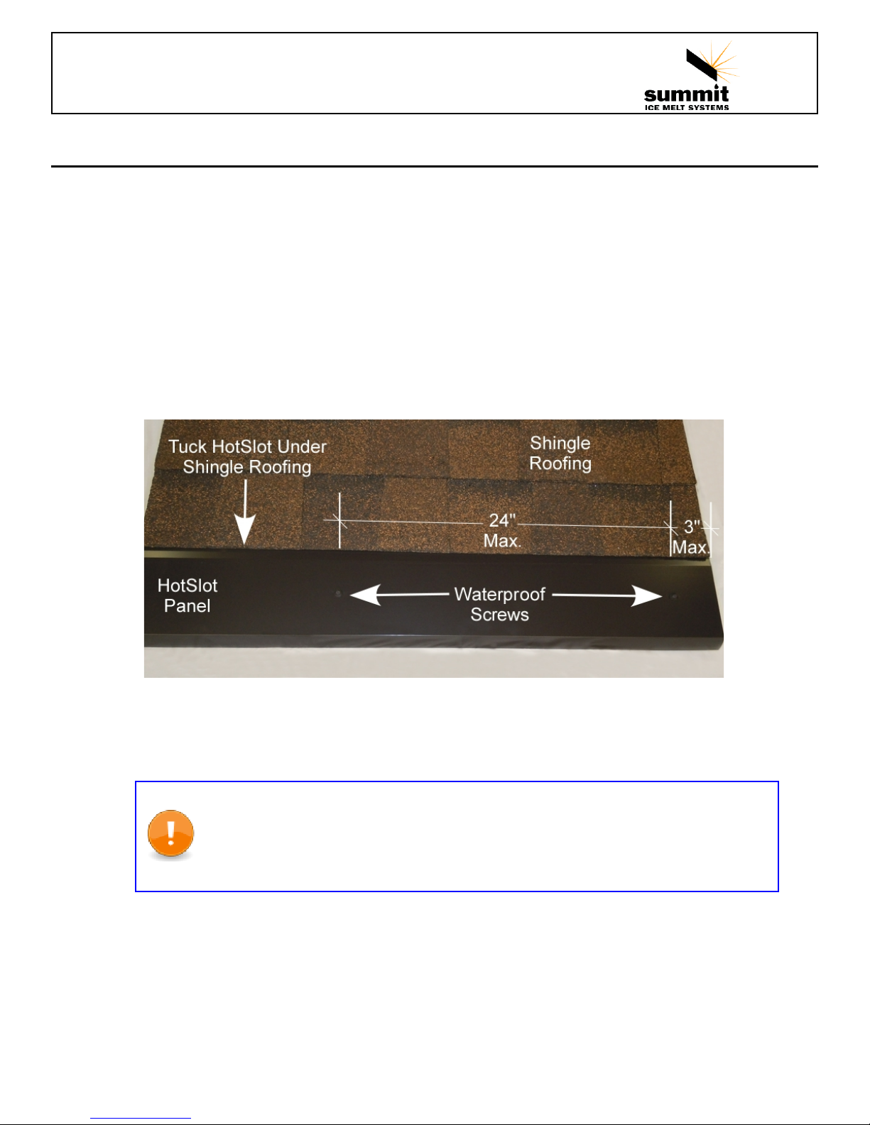
HotSlot is intended for lighter ice and snow conditions on certain metal and
composition shingle roofs. If conditions warrant, consider the more robust,
patented Radiant Edge PRO
TM
or LT
TM
ice melt systems.
For the names of manufacturers of snow guards or snow fences, contact
your Summit Ice Melt Systems' representative, or contact Summit Ice Melt
Systems' directly at (530) 583-8888.
If your application conditions are different, or if you have any questions,
contact your Summit Ice Melt Systems' representative, or contact Summit
Ice Melt Systems directly at (530) 583-8888.
How To Use This Guide
This installation guide presents Summit Ice Melt Systems’
recommendations for installing the Radiant Edge HotSlot roof edge ice
melt system. It provides design and performance data, heating cable
layout installations, electrical hookup and testing. Following these
recommendations will result in a reliable, energy-efficient system. Read
and understand this entire guide before installation.
Page 3 of 2

IMPORTANT NOTICE:
• Area laws differ concerning the handling and installation of heating
cables, building materials, electrical connections, etc.
• Please check and comply with your local laws.
• Summit Ice Melt Systems, Inc. will not be held responsible for those who do not
comply with their local or national laws while installing its products.
Summit Ice Melt Systems
PO Box 6 28, Tahoe City, CA 6145
Ph: 530-583-8888 Fax: 530-583-7777
www.SummitIceMelt.com
Other Required Documents
This guide is not intended to provide comprehensive installation
instructions. For complete Radiant Edge HotSlot de-icing system
installation instructions, please refer to the following additional required
documents:
• Additional installation instructions that are included with the heating
cable power connection kits, thermostats, controllers, and accessories.
If you do not have these documents, you can obtain them from the
Summit Ice Melt Systems web site at www.summiticemelt.com.
Ensure you are using the most current edition of the Installation and
Operation Guide by contacting info@summiticemelt.com.
For products and applications not covered by this design guide, please
contact your Summit Ice Melt Systems' representative, or contact Summit
Ice Melt Systems directly at (530) 583-8888.
Page 4 of 2

Summit Ice Melt Systems
PO Box 6 28, Tahoe City, CA 6145
Ph: 530-583-8888 Fax: 530-583-7777
www.SummitIceMelt.com
Safety Guidelines and Document Conventions
As with any electrical equipment, the safety and reliability of any system
depends on the manner in which they are installed and maintained.
Incorrect design, handling, installation, or maintenance of any of the
system components could damage the system and may result in
inadequate performance, overheating, electric shock, or fire. To minimize
these risks and to ensure that the system performs reliably, read and
carefully follow the information, warnings, and instructions in this guide.
This symbol identifies important instructions or information.
This symbol identifies particularly important safety warnings that must be
followed.
ARNING: To minimize the danger of fire from sustained electrical arcing
if the heating cable is damaged or improperly installed, and to comply with
the requirements of Summit Ice Melt Systems, agency certifications, and
national electrical codes, ground-fault equipment protection must be used
on each heating cable branch circuit. Arcing may not be stopped by conventional
circuit protection.
Please exercise all safety precautions necessary when using ladders,
scaffolding, tools.
Page 5 of 2

Summit Ice Melt Systems
PO Box 6 28, Tahoe City, CA 6145
Ph: 530-583-8888 Fax: 530-583-7777
www.SummitIceMelt.com
System Overview
Summit Ice Melt Systems’ Radiant Edge HotSlot system can prevent ice
dams and icicles by maintaining a continuous path for melt water to drain
from the roof. HotSlot system uses a sophisticated self-regulating heating
cable which reduces heat output automatically as the heating cable
warms to above freezing, resulting in lower energy use while eliminating
the possibility of overheating. A typical Summit Ice Melt system includes
the HotSlot Panels, self-regulating heating cables, heating cable
connection kits, control system and power distribution.
Radiant Edge HotSlot is suitable for slopes down to 2/12.
System Components
A typical system may include the following:
• Radiant Edge HotSlot Panels
• Radiant Edge Valley Base Panels
• Radiant Edge Valley Cover Panels
• Waterproof Screws
• S1 (110Vac) or S2 (208-277Vac) self regulating heating cable
• Heating cable connection kits and accessories
• Controller system
• Power distribution
WARNING: The Radiant Edge ice melt system MUST be protected with a
ground fault protection device per local codes and the NEC (National
Electric Code) and CSA (Canadian Standards Association).
Page 6 of 2

Summit Ice Melt Systems
PO Box 6 28, Tahoe City, CA 6145
Ph: 530-583-8888 Fax: 530-583-7777
www.SummitIceMelt.com
General Procedures
1. Review the following:
A. Packing List and materials provided
B. Radiant Edge System Layout drawings (may be sent
separately) with panels identified, junction box and controller
locations noted, sensor location
C. Access Equipment (ladders, scaffolding, safety harnesses,
etc.)
D. On some systems, each cover and base panel is numbered.
If so, position each base piece on the roof as designated in
the Layout Drawings.
Tools Required
• Chop saw, Skilsaw or portable
bandsaw with aluminum / copper
cutting blade
• Megohmeter Tester: 500, 1000,
2500 Vdc
• Multimeter
• Tape Measure
• Tin Snips
• Wire cutter
• Wire stripper
• Straight edge knife
• Drill
• Driver for screws
• 3/8" metal bit
• Deburring tool
• Caulk and caulking gun
Additional Materials Needed
• Cleaning solvent (i.e., denatured
alcohol) and rags for valley areas
• Adhesive
• Masking Tape
• Touch Up Paint
• Roofing Adhesive, DuraLink by
Chemlink, or equal
• Roofing Sealant, DuraSil by
Chemlink, or equal
Page 7 of 2

Summit Ice Melt Systems
PO Box 6 28, Tahoe City, CA 6145
Ph: 530-583-8888 Fax: 530-583-7777
www.SummitIceMelt.com
Installation
Roof Preparation
The proper preparation of the roof is needed to ensure optimal energy
efficiency, performance, and to prevent leaks.
Radiant Edge HotSlot is suitable for slopes down to 2/12.
1. Existing Metal roofs): Trim back metal to flush to the eave
and remove fasteners on bottom 7" of roofing panel prior to
installing HotSlot.
2. Existing Composition Shingle: Carefully pry up second course of
shingles with a broad paint scraper or similar tool. Install HotSlot
along eave on first shingle course and tuck under second course of
shingles.
3. New Composition Shingle: Install starter and first course of
shingles. Install HotSlot along eave on first shingle course.
Continue installing shingles with standard exposure.
4. On other conditions such as existing shakes, slate, tile and
standing seam roofing, consider using the patented Radiant Edge
PRO™ or LT™ ice melt systems.
Page 8 of 2

Summit Ice Melt Systems
PO Box 6 28, Tahoe City, CA 6145
Ph: 530-583-8888 Fax: 530-583-7777
www.SummitIceMelt.com
HotSlot Panel Installation
1. Determine the layout of the system. Place full-sized HotSlot
panels flush to each end of the roof. Tuck top edge under second
course of shingles.
2. The remaining panels shall be installed between the end panels,
and have a minimum 0.25" gap between them.
3. Miter cut HotSlot Panel at valleys, leaving clearance for Radiant
Edge Valley system.
Radiant Edge HotSlot Figure A
For a more waterproof installation on existing shingle roofs, apply a heavy
bead of caulking on the bottom side of the panel around each attachment
hole and along the top flange edge.
Page of 2

Where specified, the roof eave panels must extend to the edges of the
roof eave (i.e., to the gable ends and rake ends). Contact your Summit
Ice Melt Systems’ representative or phone Summit at 530-583-8888 if
actual field dimensions are significantly different from design
dimensions and Layout Drawings. Failure to do this may cause melted snow
to re-freeze at the unheated areas and form icicles and ice dams.
Summit Ice Melt Systems
PO Box 6 28, Tahoe City, CA 6145
Ph: 530-583-8888 Fax: 530-583-7777
www.SummitIceMelt.com
HotSlot Panel Installation, (Cont’d.)
4. Using waterproof screws, attach the panels through the factory
pre-drilled holes (five fasteners for 8' panel). If panels are less
than full length, ensure a fastener is within 3" of each end, and
spacing no greater than 24" O.C. Keep fasteners 5" away from
center of valley.
5. Center the screw in the hole before securing; set the screw so the
neoprene gasket bubbles out slightly from under the metal dome
head. Do not over-drive.
Ensure that the full shank thickness of the screw penetrates a
minimum 1" into the roof wood substrate, or penetrates the full
shank diameter (excludes the tapered point) through the wood,
whichever is less. Some conditions do not allow adequate
penetration of Summit’s fasteners. It is up to the installer to
determine and procure suitable fasteners as needed. Summit
recommends the fasteners be installed through the wood deck
and into the supporting wood members.
Page 10 of 2

Warning: The Valley Base Panels should extend all the way down to
the roof eave (the lower edge of the valley flashing). Failure to do so
may cause melted snow to re-freeze at the unheated areas and form
icicles and ice dams.
Summit Ice Melt Systems
PO Box 6 28, Tahoe City, CA 6145
Ph: 530-583-8888 Fax: 530-583-7777
www.SummitIceMelt.com
Valley Installation
Radiant Edge HotSlot Figure B
1. If the valley uses a metal “W” valley flashing, the Valley Panel is placed on
one side of the “W”. Installing the Valley Base Panel on the side of the
valley with less ‘watershed’ is preferred.
2. For shingle roofs with “woven” valleys, i.e., when no metal flashing is used,
the Valley Base Panel may be installed directly onto the shingles.
3. If required, trim the edge of the roofing materials on the side where the
Valley Base is to be installed.
4. Prepare valley metal by cleaning away debris and cleaning the metal
surface with a solvent such as isopropyl alcohol.
5. Apply a continuous bead of approved adhesive to bottom side of the Valley
Base; allow 1" spaces between the Valley Bases. Use masking tape or
some form of securement to temporarily hold valley base until adhesive
cures.
Page 11 of 2

Summit Ice Melt Systems
PO Box 6 28, Tahoe City, CA 6145
Ph: 530-583-8888 Fax: 530-583-7777
www.SummitIceMelt.com
Heating Cable Installation
Prior to starting installation:
• Test the heating cable insulation resistance to confirm that the
heating cable has not been damaged during shipping (see
Electrical Testing, Pages 15-16). All cable has been factory tested
prior to shipment.
• Visually check the components for damage.
• Make sure that all material is included as indicated on the Packing
Slip.
• Make sure that you will be using a ground-fault equipment
protection device (GFEPDs) with a 30mA trip level to power the
circuit. Nuisance tripping can occur if you use 5mA trip level
ground fault interrupters (GFIs) even with undamaged heating
cable.
• Protect the heating cable ends from moisture and mechanical
damage if they will be left exposed before connection.
• Compare the heating cable received with the design voltage
required to ensure the heating cable is right for your installation.
The voltage is clearly marked on the heating cable.
• Compare the design circuit lengths with the heating cable lengths
received in order to minimize the need for splicing.
• Ensure that the heating cable required does not exceed the
maximum circuit length for the voltage and circuit breaker rating to
be used (see page 2 ).
ARNING: Take special care to protect the heating cable and outer jacket
from damage when routing through the PRO Base and Valley Base panels
and adjacent roofing and flashings. To optimize energy efficiency, heating
cable clearances within slots are very tight. Pre-bending the heating cable
by hand is recommended prior to installation and will enable an easier, safer
installation. Damaged heating cable must be replaced or properly repaired prior to
installing PRO Cover Panel.
Page 12 of 2

ARNING: Taping heating cable ends is NOT acceptable.
Summit Ice Melt Systems
PO Box 6 28, Tahoe City, CA 6145
Ph: 530-583-8888 Fax: 530-583-7777
www.SummitIceMelt.com
Heating Cable Installation (Cont’d.)
1. Once the HotSlot and Valley Base Panels have been installed and
adhesives cured, if applicable, the heating cable is ready for
installation.
2. Follow the heating cable Power Connection Kit instructions, and
install the End Seal as directed. The End Seal will protrude beyond
the HotSlot Panel. End Seal may be better concealed if folded
down under the Panel and affixed to the fascia.
3. Start with the heating cable end terminated with the End Seal.
Leave the End Seal beyond the edge of the roof and work your way
back to the other end of the system per the Layout Drawings. Press
the heater cable into the slot behind the drip edge. Ensure cable is
seated completely into the slot. See Figure C.
Radiant Edge HotSlot Figure C
Page 13 of 2

Summit Ice Melt Systems
PO Box 6 28, Tahoe City, CA 6145
Ph: 530-583-8888 Fax: 530-583-7777
www.SummitIceMelt.com
4. If applicable, continue tracing up one side of Valley Base and
return down other side of base. It maybe helpful to temporarily
remove the adjacent mitered HotSlot Panel to insert and twist the
Heater Cable. Re-install.
5. Be sure to leave a drip loop at components so that water will not
track down the heating cable into the component. Install the
heating cable using the Layout Drawings provided.
6. Be sure to leave enough heating cable to connect to the junction
box.
7. Be sure to leave drip loops where appropriate.
8. Be sure to loop and secure the heating cable at the bottom of
downspouts so that the heating cable is not exposed to mechanical
damage. Use protective downspout brackets for heating cable.
. Use UV resistant heating cable ties whenever two heaters are
intended to stay together.
10. Visually inspect the heating cable for mechanical damage and test
the entire circuit for insulation resistance prior to applying power.
(See Electrical Hookup, page 17).
hen installing the heating cable:
• Do not pull it over sharp edges.
• Do not use excessive pulling force.
• Do not kink or the crush heating cable.
• Do not walk on the heating cable.
• Protect heating cable from sharp edges, such as sheet metal
covers, with electrical tape.
ARNING: Shock and fire hazard. Damaged heating cable or
components can cause electrical shock, arcing, and fire. Do not attempt to
energize damaged heating cable or components. Replace them
immediately using a new length of heating cable and the appropriate
accessory.
Page 14 of 2

NOTE: Prior to electrical hookup, test the electrical insulation resistance of
the heating cable. Every foot of heater cable provided by Summit Ice Melt
Systems has been tested and approved in the factory for insulation
integrity.
ARNING: Shock or fire hazard. Disconnect power to all circuits prior to
testing.
Summit Ice Melt Systems
PO Box 6 28, Tahoe City, CA 6145
Ph: 530-583-8888 Fax: 530-583-7777
www.SummitIceMelt.com
Electrical Testing
Megohmeter Test
The insulation resistance test is critical to ensure the safety and reliability
of the heating cable system. This test should be performed at four
stages: 1) when cable is received, 2) after cables are installed in system,
3) prior to initial startup, 4) as part of the regular system inspection.
Use a megohmeter, test insulation with 500 and 1000Vdc voltages. IEEE
515.1 recommends testing be done at 2500 Vdc, as some problems may
not be detected at lower voltages.
First, measure the resistance between the heating cable bus wires and
the grounding braid; then measure the insulation resistance between the
braid and the metal Eave Panel Cover, metal roofing, and gutter.
Testing Procedure
1. Disconnect all power to the heating cable, thermostat, and contactor.
2. Set test voltage 0 volts Vdc.
3. Connect the negative lead (-) to the heating cable metallic braid.
4. Connect the positive lead (+) to both heating cable bus wires.
5. Turn on Megohmeter and set the voltage to 500 Vdc; apply the voltage
for 1 minute. Record the resistance in the Installation Log, Page 23.
6. Repeat Step #5 for 1000Vdc (and the recommended 2500 Vdc).
7. Turn off the Megohmeter.
8. If the megohmeter does not self-discharge, discharge phase connection
to ground with a suitable grounding rod. Disconnect the megohmeter.
. Re-connect the thermostat or contactor and re-energize the system.
Page 15 of 2

ARNING: Shock or fire hazard. Disconnect power to all circuits prior to
testing.
Summit Ice Melt Systems
PO Box 6 28, Tahoe City, CA 6145
Ph: 530-583-8888 Fax: 530-583-7777
www.SummitIceMelt.com
Electrical Testing: Megohmeter Test (Cont’d.)
Insulation Resistance Criteria
A clean, dry, properly installed circuit should measure thousands of
megohms, regardless of the heating cable length or measuring voltage (0-
2500 Vdc). The following criteria are provided to assist in determining the
acceptability of an installation where optimum conditions may not apply:
• All three insulation resistance values should be greater than 20
megohms.
• Insulation resistance values for any particular circuit should not
vary more than 25% as a function of measuring voltage.
• Reading must be steady at measuring voltage.
• If any of these conditions are not met, consult the
“Troubleshooting” instructions on Pages 24-25.
Continuity Test
This continuity test is useful in determining if the heating cable is
damaged or was not connected correctly. This test can also be performed
as part of the troubleshooting procedure. Note: some of the heating cable
components, such as the End Seal kit and heater cable power
connection, and splice/tee kits which utilize heat-shrink tubings, may not
re-enterable and will have to be replaced after this test is done.
1. Disconnect all power to heating cable, thermostat, and contactor.
2. Twist the two bus wires together at one end.
3. Take a resistance reading from bus wire to bus wire at the other
end. The reading should be 3 ohms or less. High readings (above
1000 ohms) generally indicate bus wire damage or misconnected
components.
4. If there are any tees on the circuit, each leg of the tee must be
tested separately.
5. Be sure to untwist the bus wires and install new components on the
circuit prior to re-energizing the circuit.
6. Re-connect the contactor or thermostat and re-energize the circuit.
Page 16 of 2

Summit Ice Melt Systems
PO Box 6 28, Tahoe City, CA 6145
Ph: 530-583-8888 Fax: 530-583-7777
www.SummitIceMelt.com
Electrical Hookup
1. It is recommended that a qualified electrician, licensed in the
jurisdiction of the installation, to conduct the hookup and testing of
the work.
2. Route the heating cable from the Radiant Edge system to the
electrical junction box. Be sure to include a drip loop at the box.
3. To complete the power connection, refer to the heating cable
Power Connection Kit instructions.
4. For heating systems which a complete control system has not been
provided, Summit Ice Melt Systems requires a 30 milliamp ground
fault circuit breaker sized for the Radiant Edge ice melt system.
5. Complete and return Installation Log (See Page 23)
ARNING: Do NOT penetrate the heating cable protective jacket with
staples, nails, etc. or route the heating cable over sharp edges that could
abrade the jacket over time.
ARNING: DO NOT use 5mA GFCI breakers, as they will likely cause
nuisance tripping and cause the heating system to malfunction.
Page 17 of 2

Summit Ice Melt Systems
PO Box 6 28, Tahoe City, CA 6145
Ph: 530-583-8888 Fax: 530-583-7777
www.SummitIceMelt.com
4CDC Controller
You may have a different controller than the 4CDC discussed here.
Consult the separate installation guide accompanying the controller for
further information regarding operation, installation and sensor placement.
If there are problems with the system not activating, refer to
“Troubleshooting” on pages 24-25.
Figure G: Summit Ice Melt Systems 4CDC Digital
Ambient Temperature Sensing Controller
Overview
Summit Ice Melt Systems, Inc. Optional 4 Circuit Digital Controller (4CDC)
provides On/Off operation of its S1 and S2 (120Vac to 277Vac) self-
regulating heater cables by energizing up to four individual branch circuits
via adjustable control values as set on the temperature controller.
The 4CDC provides a set point for on/off operation as well as a low-temp
cutout of the circuits. The low-temp cutout shuts the system off when
temperatures are so cold that no snow and ice melting occurs. Both
temperatures are easily field adjustable to suit local conditions.
Page 18 of 2

Summit Ice Melt Systems
PO Box 6 28, Tahoe City, CA 6145
Ph: 530-583-8888 Fax: 530-583-7777
www.SummitIceMelt.com
4 CDC Controller (Cont’d.)
Operation
The 4CDC controller uses a thermistor to sense ambient temperatures. When the
temperature drops below the Heater-On set-point, the system is energized. When the
temperature rises above the Heater-On set-point, the system is de-energized.
If the temperature drops below the low-temp cutoff, the system is de-energized. When
the temperature rises above the low-temp cutoff, the system is energized.
The 3-position rocker switch allows the operator to set the system in Automatic,
Manual (system is energized no matter what ambient conditions are), or Off mode
(center position).
Installation
The 4CDC controller has an enclosure that is 10" high, 8" wide, and 4" deep. It has a
NEMA 4/12 rating, so it may be mounted indoors or outdoors, typically near the circuit
breaker panel. Each branch circuit must be protected by a ground fault protection
device per the NEC. A 120Vac protected circuit is required to energize the controller.
The ambient sensor is mounted outdoors in a shaded location representative of
minimum ambient conditions (typically on the north side of a building), and away from
any heat source, such as direct sunlight or a utility room exhaust vent, so that the
temperature sensor gives an accurate reading of the air temperature reflective of
actual ambient conditions. The ambient sensor comes with a standard 10 ft lead, but
its range can be extended up to hundreds of feet using ordinary stranded copper wire.
Pre-Season Testing
The heater circuits may be energized and tested for proper functionality prior to the
cold weather season by simply setting the 3-position rocker switch to Manual.
Amperage readings may then be taken on each branch circuit. Amperage will depend
on ambient temperature and time. Follow heater manufacturer test procedures.
Page 1 of 2
This manual suits for next models
1
Table of contents