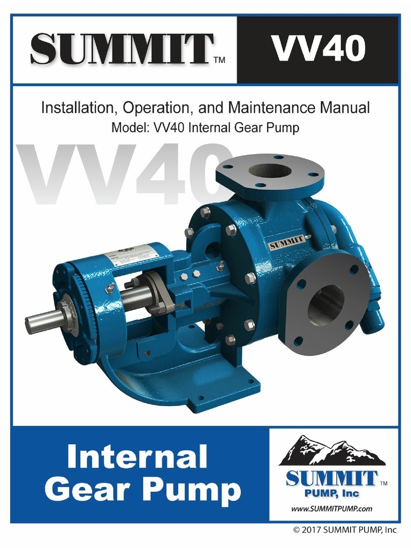
Summit CC User manual

Installation, Operation, and Maintenance Manual
SUMMIT PUMP MODEL CCFM GENERAL PURPOSE i


INSTALLATION, OPERATION, AND MAINTENANCE MANUAL
I.WARRANTY
Pumping units assembled by Summit Pump, Inc., Green Bay, WI are guaranteed to be free from defects in
material and workmanship for one year from date of shipment from factory in Green Bay, WI. The
obligation under this warranty, statutory or otherwise, is limited to replacement or repair at Green Bay, WI,
of such part as shall appear to us upon inspection at such point, to have been defective in material or
workmanship.
This warranty does not obligate Summit Pump, Inc. to bear the cost of labor or transportation charges in
connection with replacement or repair of defective parts; nor shall it apply to a pump upon which repairs or
alterations have been made unless authorized by Summit Pump, Inc.
No warranty is made in respect to engines, motors, or trade accessories, such being subject to warranties of
their respective manufacturers.
No express implied or statutory warranty, other than herein set forth is made or authorized to be made by
Summit Pump, Inc.
In no event shall Summit Pump, Inc. be liable for consequential damages or contingent liabilities arising out
of the failure of any Summit Pump, Inc. pump or parts thereof to operate properly.
II.LIABILITY
Summit Pump, Inc. shall not be liable for personal physical injury, damage or delays caused by failure to
follow the instructions and procedures for installation, operation and maintenance contained in this manual.
The equipment is not for use in or with any nuclear facility or fire sprinkler system. Buyer accepts the
responsibility for insuring that the equipment is not used in violation and Buyer shall indemnify and hold
Seller harmless from any and all liability (including such liability resulting from seller’s negligence) arising
out of said improper use.
III.COPYRIGHT
This Installation, Operation, and Maintenance Manual contains proprietary information, which is protected
by copyright. No part of this Installation, Operation, and Maintenance Manual may be photocopied or
reproduced without prior written consent from Summit Pump.
The information contained herein is for informational use only and is subject to change without notice.
Summit Pump assumes no responsibility or liability for any errors or inaccuracies that may appear in this
manual.


Installation, Operation, and Maintenance Manual
SUMMIT PUMP MODEL CCFM GENERAL PURPOSE i
1 CONTENTS
1CONTENTS..............................I
2INTRODUCTION ..................... 2
3SAFETY .................................. 3
3.1 PUMP SAFETY WARNINGS ....................... 3
4NOMENCLATURE................... 5
4.1 NAMEPLATE INFORMATION ............................ 5
4.2 MODEL NO. ................................................ 5
4.3 MATL......................................................... 5
4.4 SERIAL NO. ................................................. 5
4.5 PEICL &PEIVL.............................................. 5
4.6 IMP.DIA.&MAX IMP.DIA............................ 6
4.7 MAX PSI @100°F ...................................... 6
4.8 NOM.RPM ................................................ 6
5RECEIPT AND STORAGE ......... 7
5.1 RECEIVING THE PUMP.............................. 7
5.2 STORING THE PUMP ................................ 7
5.2.1 Temporary ........................................ 7
5.2.2 Long Term......................................... 7
5.3 HANDLING ............................................... 7
5.4 LIFTING .................................................... 7
6INSTALLATION....................... 8
6.1 GENERAL.................................................. 8
6.2 LOCATION ................................................ 8
6.3 BASE PLATE .............................................. 8
6.4 FOUNDATION .......................................... 8
6.4.1 Concrete Sub-Base ........................... 8
6.5 BASE PLATE GROUTING............................ 9
6.6 ROTATION AND ORIENTATION .............. 10
6.6.1 Rotation.......................................... 10
6.6.2 Orientation ..................................... 10
6.7 PIPING CONNECTION –SUCTION /
DISCHARGE ............................................ 11
6.7.1 Suction Piping................................. 11
6.7.2 Discharge Piping ............................. 11
7OPERATION ......................... 12
7.1 CHECKING ROTATION ............................ 12
7.2 FIRST RUN CHECK................................... 12
7.2.1 Start Up .......................................... 13
7.2.2 Shut Down...................................... 13
7.3 LUBRICATION............................................. 13
7.3.1 Grease ............................................ 14
7.3.2 Lubrication Frequency.................... 14
7.3.3 Lubrication Amount ....................... 14
8MAINTENANCE TIMETABLE. 15
8.1 DAILY MAINTENANCE ............................ 15
8.2 SIX MONTH MAINTENANCE................... 15
8.3 YEARLY MAINTENANCE ......................... 15
9TROUBLESHOOTING............ 16
9.1 PUMP PROBLEMS .................................. 16
9.2 PROBABLE CAUSE AND REMEDY............ 16
10 EXPLODED VIEWS ............... 17
10.1 FM1 &FM2 CAST IRON/BRONZE,FM2
STAINLESS................................................. 17
10.2 FM1 STAINLESS......................................... 18
10.3 CC1 &CC2 CAST IRON/BRONZE,CC2 STAINLESS
....................................................... 19
10.4 CC1 STAINLESS.......................................... 20
11 DISASSEMBLY MODEL CCFM 21
11.1 LIQUID END............................................ 22
11.2 ADAPTOR KIT ......................................... 22
11.3 POWER END........................................... 23
12 ASSEMBLY MODEL CCFM .... 25
12.1 POWER END........................................... 27
12.2 ADAPTOR KIT ......................................... 28
12.3 LIQUID END............................................... 29
13 CASING RING WEAR............ 30
15 APPENDIX E – REFERENCE
TABLES................................ 32
15.1 TORQUE GUIDELINES............................. 32
15.1.1 Bolt Torques ................................... 32
16 ZAPPENDIX F – PUMP
DIMENSIONS....................... 34
17 PUMP INFORMATION ......... 36

INSTALLATION, OPERATION, AND MAINTENANCE MANUAL
2 SUMMIT PUMP MODEL CCFM GENERAL PURPOSE
2 INTRODUCTION
This installation, operation, and maintenance manual is designed to help you achieve the best
performance and longest life from your Summit Pump.
This pump is a centrifugal pump which generates pressure, not flow. Velocity imparted to the casing
from the impeller tip is converted from velocity energy to pressure energy; flow is a byproduct of the
differential pressure.
Fluid from the suction eye is dispersed through the impeller in the volume between the impeller
vanes. Fluid leaves the vane tip at approximately the same speed as the vane tip, the fluid
immediately collides with the casing wall and the velocity energy is converted to pressure energy. If
allowed, the fluid will leave the discharge port towards a lower pressure.
If there are any questions regarding this pump or its application, which are not covered in this
manual, please contact your local Summit Pump, Inc. Distributor.
For information or technical assistance on the driver service, contact the driver manufacturer’s local
dealer or representative.
Figure 2-1: Basics of centrifugal design

INSTALLATION, OPERATION, AND MAINTENANCE MANUAL
SUMMIT PUMP MODEL CCFM GENERAL PURPOSE 3
3 SAFETY
The following message types are used in this manual to alert maintenance personnel to procedures
that require special attention for the protection and safety of both personnel and equipment:
DANGER
Imminently hazardous situation which, if not
avoided, will result in death or serious
injury.
WARNING
Potentially hazardous situation which, if not
avoided, could result in death or serious
injury.
CAUTION
Potentially hazardous situation which, if not
avoided, may result in minor or moderate
injury.
NOTICE
Includes Information on operation,
maintenance, rules or directions. May
indicate possible property damage.
3.1 PUMP SAFETY WARNINGS
The safety information below should be followed and observed to prevent damage to equipment
or injury to operators:
DANGER
Ensure discharge line is open and free of
clogs before operation. Negligent acts may
result in serious injury or death.
CAUTION
Feeding very hot or very cold fluid into the
pump at room temperature may result in
fracture of pump wet end.

INSTALLATION, OPERATION, AND MAINTENANCE MANUAL
4 SUMMIT PUMP MODEL CCFM GENERAL PURPOSE
WARNING
Follow all auxiliary equipment (motors,
drives, couplings etc.) manufacturer’s
manuals, instructions or procedures during
installation, operation and maintenance of
the pump.
NOTICE
Check all clearances, drive to shaft
alignments, fastener torques, equipment
lubrication, gaskets and seals for leaks and
that all equipment is fastened into place
before operation.

INSTALLATION, OPERATION, AND MAINTENANCE MANUAL
SUMMIT PUMP MODEL CCFM GENERAL PURPOSE 5
4 NOMENCLATURE
4.1 Nameplate information
On page 36 of this manual, record the nameplate data from your pump. This will assist with any
maintenance questions or pump identification in the future.
Figure 4-1 shows the pump nameplate for the
CCFM product line. This will be applied to the
completed pump and should be permanently
fastened for the life of the pump.
Removal of this tag is illegal when PEI (Pump
Energy Index) information is defined. This
information is reported with the DOE (Department
of Energy) and the Manufacturer is defined as
Summit Pump Inc.
This tag may only be removed if the new seller has tested the equipment though DOE’s testing
requirements defined in “10 CFR Part 431 Subpart Y Pumps” and complete the required reporting of
results to the DOE. By doing this, the new seller becomes the Manufacturer and can attach their
nameplate with their PEI information.
Adding additional equipment such as motors or VFDs are allowed but PEI information and
equipment must remain as it was sold from the Manufacturer.
4.2 Model No.
Summit CCFM pumps are defined by their Model No., which is the basic model number that
defines the pump with the DOE. The basic model number is defined by equipment family (Frame
Mounted or Close Coupled), Frame size (1 or 2) and the pump size (example: 3x4-10A)
Model No. Example: FM1-3x4-10A
In this example, the pump is Frame Mounted, frame size 1, with a 3 inch discharge, 4 inch
suction and 10 inch impeller diameter (always check curve for max impeller diameter). The “A”
denotes the impeller and casing design as some pumps have the same identifiers.
4.3 Matl.
This field identifies the material group of the pump. Most cases the will define the major wetted
components material. (i.e: SS, CI/BRZ)
4.4 Serial No.
This is Summit Pump’s number designated to each individual pump sold. Using this number to
trace each individual pump build and order.
4.5 PEICL & PEIVL
PEI (Pump Energy Index) is the matrix used to compare similar design pumps as defined with the
DOE. PEICL (constant load) is used with bare pumps and pumps with motors. PEIVL (variable
load) is used when sold with VFDs.
Figure 4-1: CCFM nameplate (pump tag)

INSTALLATION, OPERATION, AND MAINTENANCE MANUAL
6 SUMMIT PUMP MODEL CCFM GENERAL PURPOSE
4.6 Imp. Dia. & Max Imp. Dia.
The Imp. Dia. Section is stating the impeller diameter the pump was sold with by the
manufacturer. The Max Imp. Dia. Section is the maximum impeller diameter that can be supplied
with the pump. This is also the diameter that the DOE testing was completed with.
4.7 Max PSI @ 100°F
This value is based on the combination of pressure and temperature at 100°F of water to reach
the MAWP (Maximum Allowable Working Pressure). Always be sure to know the MAWP based
upon the specific application.
4.8 Nom. RPM
This is either 1800 RPM or 3600 RPM and correlates with the PEI number. If no operation speed
is given with the PO, the worst case PEI number (higher PEI) will be used and may not be the
actual operation RPM.
Pump Size
Temperature
(°F)
M AWP
(PSIg)
0-150 175
151-200 165
201-225 155
FM1, FM2,
CC1 & CC2
Maximum Allowable Working Pressure
(MAWP)
Table 4-1: Maximum allowable working pressure
for Cast Iron/Bronze and Stainless Steel

INSTALLATION, OPERATION, AND MAINTENANCE MANUAL
SUMMIT PUMP MODEL CCFM GENERAL PURPOSE 7
5 RECEIPT AND STORAGE
5.1 RECEIVING THE PUMP
Immediately upon arrival, carefully inspect the pump for evidence of damage during transit.
Immediately report any damage to your local Summit Pump, Inc. Distributor.
5.2 STORING THE PUMP
5.2.1 Temporary
Temporary storage: less than six months.
1. Flush the pump with clean water. If pumped product is water reactive, remove the suction
and discharge line after draining the pump, and with compressed air blow all liquid from
cavity. Lightly cover all internal metal parts with oil and replace the suction and
discharge lines if needed.
2. Store pump in a clean, dry place, free from extreme swings in temperature and humidity.
3. Cover with a protective covering to reduce dust contamination.
4. Rotate the shaft once a week to protect the bearings from brinelling the raceway and/or
balls.
5.2.2 Long Term
Long Term Storage: more than six months.
1. Follow temporary storage guidelines 1-4 in section 5.2.1.
2. Coat all unpainted and machined surfaces with a rust inhibitor, such as LPS-3.
5.3 HANDLING
Pump unit boxes and crates may be unloaded using a forklift or slings depending on size and
package construction.
WARNING
Pump and assemblies are heavy, improper
handling could result in serious injury.
5.4 LIFTING
To avoid damage to pump and/or motor use a nylon, chain, or a wire rope sling. The slings should
be placed so lift is equally supported at four or more points.
WARNING
Be sure all components are securely
fastened to baseplate before lifting.

INSTALLATION, OPERATION, AND MAINTENANCE MANUAL
8 SUMMIT PUMP MODEL CCFM GENERAL PURPOSE
6 INSTALLATION
6.1 GENERAL
Summit Pumps are assembled at the factory. The pumps are ready to be installed and put into
service. Follow all instruction tags on the pump. Ensure all fluid properties and application
requirements have been considered and relayed to manufacturer and/or distributor. Suction piping
should be as short and direct as possible.
6.2 LOCATION
If the pump is going to have a water flush, it should be located as close as possible to the supply of
water. Other location considerations are: easy access for inspection, maintenance and ample
overhead space for lifting with crane or hoist.
6.3 BASE PLATE
Each pump unit should be mounted on a fabricated steel base plate. The base plate should be
mounted on a concrete sub base 4” to 8” longer and wider than the fabricated base plate.
6.4 FOUNDATION
Use a foundation that is sufficient enough to support all points of the pump base-plate. Level and
grout the base-plate per standard construction practices.
6.4.1 Concrete Sub-Base
The concrete sub foundation performs a number of functions. It must support the weight of the
entire pump assembly, maintain the alignment of all system components, and absorb the loads,
forces and vibrations that are developed under normal operating conditions. The concrete material
used must be top quality and conform to local building codes as well as the contractor’s strength
requirements. Reinforcing bars and mesh should be used as required. The mounting surface of the
concrete foundation must be flat and level beneath the footprint of the sub-base, or the pump could
be installed out of square. This could create problems aligning the piping, place extra loads on the
couplings and bearings, and alter the operating levels of lubricants or hydraulic fluids in the
system. It is recommended that the top surface of the slab be held flat and level to at least F50
according to American Concrete Institute (#117) and the Canadian Standards Association
(#A23.1) which is approximately 1/8” per 10 foot. The sub base height is usually determined by
the process piping runs and elevation.
The weight of the sub foundation should be 3-5 times the weight of the pump, motor and
baseplate. Dimensionally, it should be 4” to 8” longer and wider than the polymer concrete or
fabricated steel base plate. Anchor bolts are installed in pipe sleeves. The pipe diameter is 2.5
times larger than the anchor bolt diameter. This sleeve/bolt assembly is embedded in the base
when poured.
The pipe sleeve should be filled with sand or plastic foam to the top of the sleeve. This will
prevent the grout material from spilling into the sleeve and reducing the movement of the sleeve
when pouring the grout.
Anchor bolt sizes: 1”-8UNC. Length is 7.5” to 10”, depending on base thickness and overall size.

INSTALLATION, OPERATION, AND MAINTENANCE MANUAL
SUMMIT PUMP MODEL CCFM GENERAL PURPOSE 9
6.5 BASE PLATE GROUTING
1. This grouting instruction assumes a concrete sub base has been put in place to accept the
baseplate. The subbase should be clean of dirt, oil and any other debris.
2. Shims/wedges should be wood.
3. Shims/wedges should be placed on the sub base, as shown in Figure 6-3. Use 2 to 3 per stack
to obtain desired gap between baseplate and sub-base. Normal gap is 1” to 1-1/2”.
4. Carefully lower baseplate with pump and motor onto sub base over anchor bolts.
5. Level baseplate to 0.125” over length and 0.088” in over width.
6. When leveling is complete, uniformly hand tighten the anchor bolts.
Figure 6-1: Anchor Bolt configuration
Figure 6-2: Wooden Wedges

INSTALLATION, OPERATION, AND MAINTENANCE MANUAL
10 SUMMIT PUMP MODEL CCFM GENERAL PURPOSE
7. Build a plywood form around baseplate supported on the sub base. It should be 3” high and 1”
to 1.5” larger than the baseplate. Its size should be large enough to include the shims or
wedges that are left in place.
8. Use a high quality non-shrinking epoxy grout, following manufacturer’s mixing and
installation instructions.
9. When grout has cured, per grout manufacturer’s recommended cure time, tighten anchor bolts
till secure.
10. When grouting is complete, check coupling alignment and re-align as necessary.
6.6 ROTATION AND ORIENTATION
6.6.1 Rotation
CCFM pumps can only be operated in a
clockwise rotation (as viewed from the driver).
If accidently operated in a counter-clockwise
direction, lock out pump and motor to remove
the casing. Ensure the impeller bolt is still
torqued correctly. Reassemble and adjust motor
wiring to rotate clockwise.
DANGER
Lock out driver power before beginning to
work on pump.
6.6.2 Orientation
The casing can be rotated through incremental angles of a full revolution. The angles depend on
the quantity of casing bolts for the particular pump size.
Figure 6-4: Correct pump rotation
Figure 6-3: Wedge Locations

INSTALLATION, OPERATION, AND MAINTENANCE MANUAL
SUMMIT PUMP MODEL CCFM GENERAL PURPOSE 11
6.7 PIPING CONNECTION – SUCTION / DISCHARGE
DANGER
Lock out driver power before beginning to
work on pump.
Connect piping in a manner that is as short and direct as possible. Independent pipe supports, and
anchors must be used in all installations. Never support piping using the pump. When threaded
connections are used, an extendable pipe or flexible connection are possible options.
CAUTION
Never use force to align piping to the pump
threaded connections.
6.7.1 Suction Piping
The piping used should be as short as possible from suction source. Piping line size should be the
same diameter as the suction nozzle. Although, this may not always be the case, as high
viscosity, fluid velocity or system constraints may cause a change in size. All elbows 90° or 45°
should be a long-sweep. Any piping that causes air to become trapped should be avoided.
6.7.2 Discharge Piping
Generally, the diameter of the discharge piping should be the same diameter as the discharge
nozzle. In certain circumstances, this will not be the case, as the fluid being pumped will cause
the use of a different pipe size. In these circumstances, the use of a reducer/expansion fitting is
needed.
It is recommended to install an isolation discharge and suction valve to isolate the pump from the
system when down for maintenance.

INSTALLATION, OPERATION, AND MAINTENANCE MANUAL
12 SUMMIT PUMP MODEL CCFM GENERAL PURPOSE
7 OPERATION
7.1 CHECKING ROTATION
The pump can only operate clockwise rotation when viewed from the motor. If the pump has been
accidently operated in a counter-clockwise rotation remove the casing and ensure proper torque on
the impeller bolt. (As a general note, the pump will produce about half the expected head at an
unknown flow if the pump is rotating counter-clockwise.)
DANGER
Lock out power to avoid personal injury or
death.
1. Lockout power to drive.
2. Remove the pump from the motor.
3. Unlock power to motor.
4. Clear personnel from immediate area, jog motor just enough to determine direction of
rotation.
5. If the motor is rotating in the wrong direction the electrical wiring will need to be
adjusted by qualified personnel. Then repeat Step 4 and 5.
6. Once rotation is in the desired direction, lockout motor and reattach pump to motor.
7. Check clearances and connect piping to pump.
8. Unlock motor, pump is ready to run.
7.2 FIRST RUN CHECK
Several items need to be checked before you put your pump into service. Each of the following
items needs to be addressed to make certain that your equipment is correctly installed.
1. Ensure all plugs, seals or packing is installed correctly.
2. Proper alignment of pump.
3. All electrical connections.
4. All instruments and gauges should be in working order.
5. Ensure there is no or very little rubbing of the casing ring and impeller hub. Adjust casing
if needed.
6. Correct pump rotation as desired, see Figure 6-1 on page 10.
7. Open the suction valve and crack open the discharge valve. There must be some
resistance when starting and evacuate any air in the line.
CAUTION
Avoid operating against closed valves or wide
open discharge valve. This can damage
driving components and cause injury.

INSTALLATION, OPERATION, AND MAINTENANCE MANUAL
SUMMIT PUMP MODEL CCFM GENERAL PURPOSE 13
NOTICE
Do not operate pump dry. Dry operation can
cause premature damage to pump
internals.
7.2.1 Start Up
1. Crack open the discharge valve to allow flow yet still give the pump resistance.
2. Before operating the pump, it must be filled with liquid. This can be done by removing
discharge piping and fill with the pumped liquid or water. (Only use water if it will not
contaminate the pumping liquid.). If in a flooded suction, opening the suction valve will fill
the pump piping.
3. Ensure the motor rotation coincides with desired pump rotation. Refer to Section 6.5 on page
10 for specific shaft rotation direction.
4. Ensure all plugs, gauges, seals are installed and any seal clips are removed.
5. Start the pump.
7.2.2 Shut Down
1. If possible, flush the pump with clean water. (Only use water if it will not contaminate the
pumping liquid.)
2. Close the discharge valve to minimum flow of the pump.
3. Shut down the pump.
4. Close both the discharge and suction valves.
7.3 Lubrication
Ensure lip seals (49, 51), bearings
(16, 18) and motor bearings (see
motor manufacturer’s
recommendations) are adequately
lubricated for the service duty. Make
sure lip seals are installed in the
correct orientation; the lips should
face away from the frame (19). The
arrows in Figure 7-1 are pointed
towards the springs which should be
visible when viewing the pump. This
allows for leakage of excess grease
since there is no overflow opening.
Bearings are greased at the factory.
Figure 7-1: Lip seal (49, 51) orientation

INSTALLATION, OPERATION, AND MAINTENANCE MANUAL
14 SUMMIT PUMP MODEL CCFM GENERAL PURPOSE
7.3.1 Grease
Acceptable greases are petroleum base or synthetic meeting NLGL grade 2. Temperature range
of the grease is -60°F to 350°F, this grease is not recommended for temperatures above 350°F.
Table 7-1: Acceptable Greases
Acceptable Greases
Citgo Mystic EP2
Keystone 81EP2
Mobil Mobil Grease XHP222
Mobil Synthetic SCH 100
7.3.2 Lubrication Frequency
Lubrication frequency depends on environment and service factors. Each operator of the pump is
responsible for determining these factors as it is impractical to identify all operating situations.
Table 7-2 below is a general recommendation of lubrication frequency.
7.3.3 Lubrication Amount
Bearings for frame 1 and 2 will require approximately 1.5oz. for inboard bearings (16) and
approximately 1.75oz. of grease for outboard bearings (18). Follow these amounts when
lubrication frequency is required.
Operation Conditions
Lubrication Frequency
Little operation. About 10 hours per week.
Air is free of dust and chemicals
1 Year
8 hour operation per 5 day week.
Air is free of dust and harmful chemicals
6 Months
Intense operation. 24 hour service with limited dust and/or
chemicals. Outdoor operation
1 Month
Table 7-2: Lubrication Frequency

INSTALLATION, OPERATION, AND MAINTENANCE MANUAL
SUMMIT PUMP MODEL CCFM GENERAL PURPOSE 15
8 MAINTENANCE TIMETABLE
8.1 DAILY MAINTENANCE
1. Check the lip seals (49, 51), casing gasket (73A) and the mechanical seal (60-80B) in the pump for
damage or leakage.
2. Verify expected flow, head and power consumption are achieved.
3. Check noise levels, fluid and bearing frame (19) temperatures.
8.2 SIX MONTH MAINTENANCE
1. Daily maintenance and the following.
2. Lubricate lip seals (49, 51) and bearings (16, 18) based upon lubrication schedule for service
intensity.
3. Inspect and/or clean suction and discharge spools for debris and wear.
8.3 YEARLY MAINTENANCE
1. All the above and the following:
2. Check and compare pump performance with published performance curve and previous data
recordings of the pump. These inspections can range from once a year, to once every three to
five years.

INSTALLATION, OPERATION, AND MAINTENANCE MANUAL
16 SUMMIT PUMP MODEL CCFM GENERAL PURPOSE
9 TROUBLESHOOTING
9.1 PUMP PROBLEMS
Pump turns, no flow. 1,2,3,4,5,8,9,10,11,12,13,14,15,16,21,22
Pump flow rate below expected capacity. 1,2,3,4,5,8,9,11,12,13,15,16,17,18,21
Pump will not produce rated pressure. 1,2,3,4,5,10,11,13,15,16,18,21,22,26,27
Pump develops too much pressure. 6,8,9,12,27
Pump no longer self-primes. 1,2,3,4,5,7,8,10,11,12,13,14,15,16,18,19,21,22
Pump won't turn/motor overloads. 2,4,5,6,7,8,9,15,18,19,20,21,23,24,25,26
Pump is very noisy/excessive vibration. 1,2,3,4,5,6,7,10,11,12,13,14,15,16,17,18,19,20,22,24,25,26
Pump runs hot. 1,2,3,4,5,6,7,8,9,10,11,12,13,14,15,16,17,18,19,20,21,22,23,24,25,26
Pump seals short life. 1,2,3,4,5,6,7,8,9,11,12,13,14,15,1617,18,19,20,23,24,25
Excessive internal wear. 1,2,3,4,5,6,7,8,9,10,11,12,13,14,15,16,17,19,20,21,22,23,24,25
9.2 PROBABLE CAUSE AND REMEDY.
NPSHA not sufficient.
1
Pump has run dry.
2
Air leaking into the pump. 3
Liquid temperature higher than stated.
4
Viscosity higher than stated. 5
Pump running too fast for application.
6
Abrasives in liquid.
7
Losses in system are greater than calculated
8
Suction or differential pressure too high. 9
Suction valve not open.
10
Suction valve partially open.
11
Discharge valve not open or partially open.
12
Clogged strainer. 13
Supply vessel empty.
14
Pump rotation wrong.
15
Minimum submergence not met
16
Velocity in suction pipe too high
17
Casing ring and Impeller hub worn. 18
Improper seal installed. 19
Inadequate lubrication.
20
Velocity in suction is too low for solids
21
Suction lift if too great and/or pump is not primed
22
Material compatibility.
23
Drive misalignment
24
Base plate loose
25
Drive not sized for horsepower required.
26
Pressure gauges are not near pump suction and discharge
27
This manual suits for next models
5
Table of contents
Other Summit Water Pump manuals
Popular Water Pump manuals by other brands

Gormann-Rupp Pumps
Gormann-Rupp Pumps JS4L60-E8.7 200/3 Installation, operation and maintenance manual

Carver Pump
Carver Pump G2C Installation, operation and maintenance instructions

Lotus
Lotus MAXIMUS ECO 800 Installation and maintenance instructions

AQUAMOTION
AQUAMOTION Aqua-Shield AMH1K-7ODRXT1 instruction sheet

Debem
Debem Equaflux 51 Instructions for use and maintenance

Dover
Dover PSG Wilden PR260 Operation & maintenance manual