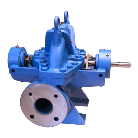
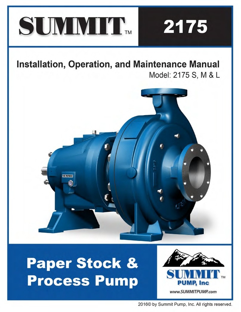
Summit VV40H Instruction manual

SUMMIT PUMP MODEL SPL PROGRESSIVE CAVITY i

INSTALLATION, OPERATION, AND MAINTENANCE MANUAL
ii SUMMIT PUMP MODEL VV40 INTERNAL GEAR PUMP

INSTALLATION, OPERATION AND MAINTENANCE MANUAL
SUMMIT PUMP MODEL VV40 INTERNAL GEAR PUMP iii
i. WARRANTY
Pumping units assembled by Summit Pump, Inc., Green Bay, WI are guaranteed to be free from defects in
material and workmanship for one year from date of shipment from factory in Green Bay, WI. The
obligation under this warranty, statutory or otherwise, is limited to replacement or repair at Green Bay, WI,
of such part as shall appear to us upon inspection at such point, to have been defective in material or
workmanship.
This warranty does not obligate Summit Pump, Inc. to bear the cost of labor or transportation charges in
connection with replacement or repair of defective parts; nor shall it apply to a pump upon which repairs or
alterations have been made unless authorized by Summit Pump, Inc.
No warranty is made in respect to engines, motors, or trade accessories, such being subject to warranties of
their respective manufacturers.
No express implied or statutory warranty, other than herein set forth is made or authorized to be made by
Summit Pump, Inc.
In no event shall Summit Pump, Inc. be liable for consequential damages or contingent liabilities arising out
of the failure of any Summit Pump, Inc. pump or parts thereof to operate properly.
ii. LIABILITY
Summit Pump, Inc. shall not be liable for personal physical injury, damage or delays caused by failure to
follow the instructions and procedures for installation, operation and maintenance contained in this manual.
The equipment is not for use in or with any nuclear facility or fire sprinkler system. Buyer accepts the
responsibility for insuring that the equipment is not used in violation and Buyer shall indemnify and hold
Seller harmless from any and all liability (including such liability resulting from seller’s negligence) arising
out of said improper use.
iii. COPYRIGHT
This Installation, Operation, and Maintenance Manual contains proprietary information, which is protected
by copyright. No part of this Installation, Operation, and Maintenance Manual may be photocopied or
reproduced without prior written consent from Summit Pump.
The information contained herein is for informational use only and is subject to change without notice.
Summit Pump assumes no responsibility or liability for any errors or inaccuracies that may appear in this
manual.

INSTALLATION, OPERATION, AND MAINTENANCE MANUAL
iv SUMMIT PUMP MODEL VV40 INTERNAL GEAR PUMP

INSTALLATION, OPERATION AND MAINTENANCE MANUAL
SUMMIT PUMP MODEL VV40 INTERNAL GEAR PUMP v
1 CONTENTS
I.WARRANTY ..............................................III
II.LIABILITY ..................................................III
III.COPYRIGHT ..............................................III
1CONTENTS.............................V
2INTRODUCTION.....................1
3SAFETY ..................................2
3.1 PUMP SAFETY WARNINGS ....................... 2
4NOMENCLATURE................... 4
4.1.1 Model Size ........................................ 4
4.1.2 Seal Type & Material ........................ 4
4.1.3 Materials of Construction................. 4
4.1.4 Additional Items ............................... 5
4.1.5 Special to Application ....................... 5
5RECEIPT AND STORAGE .........7
5.1 RECEIVING THE PUMP.............................. 7
5.2 STORING THE PUMP ................................ 7
5.2.1 Temporary ........................................ 7
5.2.2 Long Term......................................... 7
5.3 HANDLING ............................................... 7
5.4 LIFTING .................................................... 7
6INSTALLATION....................... 8
6.1 GENERAL.................................................. 8
6.2 LOCATION ................................................ 8
6.3 BASE PLATE .............................................. 8
6.4 FOUNDATION .......................................... 8
6.4.1 Concrete Sub-Base ........................... 8
6.5 BASE PLATE GROUTING............................ 9
6.6 ORIENTATION AND ROTATION .............. 11
6.6.1 Casing Orientation.......................... 12
6.7 PIPING CONNECTION –SUCTION /
DISCHARGE ............................................ 12
6.7.1 Suction Piping ................................. 12
6.7.2 Discharge Piping ............................. 12
6.8 ALIGNMENT ........................................... 13
6.8.1 Coupling Connected Units .............. 13
6.8.2 Belt Driven Units............................. 13
6.8.3 Alignment Checks ........................... 13
7OPERATION......................... 14
7.1 CHECKING ROTATION ............................ 14
7.2 LUBRICATION......................................... 14
7.2.1 Packing ........................................... 14
7.2.2 Bearings .......................................... 15
7.2.3 Grease ............................................ 15
7.3 PACKING ................................................ 15
7.3.1 Packing Adjustment ....................... 16
7.3.2 Packing Lubrication ........................ 16
7.4 MECHANICAL SEALS .............................. 17
7.5 FIRST RUN CHECK .................................. 17
7.5.1 Start Up .......................................... 17
7.5.2 Shut Down...................................... 18
8MAINTENANCE TIMETABLE. 19
8.1 DAILY MAINTENANCE ............................ 19
8.2 THREE MONTH MAINTENANCE ............. 19
8.3 SIX MONTH MAINTENANCE................... 19
8.4 YEARLY MAINTENANCE ......................... 19
9TROUBLESHOOTING............ 20
9.1 PUMP PROBLEMS .................................. 20
9.2 PROBABLE CAUSE AND REMEDY............ 20
10 EXPLODED VIEWS ............... 21
10.1 VV40H &VV40HL CAST IRON.................... 21
10.2 VV40H &VV40HL STAINLESS STEEL............ 22
10.3 VV40H &VV40HL CAST IRON &STAINLESS
STEEL –BEHIND ROTOR MECHANICAL SEAL .... 23
10.4 VV40L, LL, LQ &LS CAST IRON &STAINLESS
STEEL....................................................... 24
11 DISASSEMBLY MODEL VV40 25
11.1 HEAD AND CASING ................................ 26
11.2 BEARING HOUSING................................ 26
11.3 REMOVING SEALS .................................. 27
11.3.1 Packing ........................................... 27
11.3.2 Component Mechanical Seal.......... 27
11.4 BRACKET AND CASING ........................... 28
11.5 INTERNAL RELIEF VALVE ........................ 28
12 ASSEMBLY MODEL VV40..... 29
12.1 BRACKET &IDLER BUSHINGS ................. 29
12.1.1 Normal installation......................... 30
12.1.2 Heated installation ......................... 30
12.1.3 Bushing Temperature Limits .......... 31
12.2 BRACKET AND CASING ........................... 31
12.3 INSTALLING SEALS ................................. 31
12.3.1 Packing ........................................... 32
12.3.2 Component Mechanical Seal.......... 32
12.4 BEARING HOUSING................................ 33
12.5 HEAD AND CASING ................................ 34
12.6 ADJUSTING END CLEARANCE................. 35
12.6.1 Measured Rotation Method .......... 35
12.6.2 Dial Indicator Method .................... 36

INSTALLATION, OPERATION, AND MAINTENANCE MANUAL
ii SUMMIT PUMP MODEL VV40 INTERNAL GEAR PUMP
12.7 INTERNAL RELIEF VALVE.........................38
12.7.1 Mounting valve on head.................38
12.7.2 Setting pressure..............................38
13 APPENDIX E – REFERENCE
TABLES ................................ 40
13.1 TORQUE GUIDELINES .............................40
13.1.1 Bolt Torques .................................. 40
13.1.2 Locknut Torques............................. 40
14 PUMP INFORMATION ..........41

INSTALLATION, OPERATION, AND MAINTENANCE MANUAL
SUMMIT PUMP MODEL VV40 INTERNAL GEAR PUMP 1
2 INTRODUCTION
This installation, operation, and maintenance manual is designed to help you achieve the best performance
and longest life from your Summit Pump.
This pump is a positive displacement internal gear type. The pump’s drive shaft turns a ring gear (rotor), with
internal teeth, which rotates the external gear (idler). The idler rotates on a pin and meshes its external teeth
with the rotor’s internal teeth.
The crescent is integrated with the pump head and spaced between the internal teeth and external teeth. As
the gear teeth disengage at the intake port, liquid enters and is trapped in the space of each gear tooth. The
liquid is carried to the discharge port. The meshing of the two gears and the space reduction, forces the liquid
from the pump through the discharge port. Figure 2-1 below illustrates the internal gear pump design
principle.
If
there are any questions regarding this pump or its application, which are not covered in this manual, please
contact your local Summit Pump, Inc. Distributor.
For information or technical assistance on the driver service, contact the driver manufacturer’s local dealer or
representative.
Figure 2-1: Priming cycle and gear pump design principle

INSTALLATION, OPERATION, AND MAINTENANCE MANUAL
2 SUMMIT PUMP MODEL VV40 INTERNAL GEAR PUMP
3 SAFETY
The following message types are used in this manual to alert maintenance personnel to procedures that
require special attention for the protection and safety of both personnel and equipment:
DANGER
Imminently hazardous situation which, if not
avoided, will result in death or serious
injury.
WARNING
Potentially hazardous situation which, if not
avoided, could result in death or serious
injury.
CAUTION
Potentially hazardous situation which, if not
avoided, may result in minor or moderate
injury.
NOTICE
Includes Information on operation,
maintenance, rules or directions. May
indicate possible property damage.
3.1 PUMP SAFETY WARNINGS
The safety information below should be followed and observed to prevent damage to equipment or injury to
operators:
DANGER
Ensure discharge line is open and free of
clogs before operation. Negligent acts may
result in serious injury or death.
CAUTION
Feeding very hot or very cold fluid into the
pump at room temperature may result in
fracture of pump wet end.

INSTALLATION, OPERATION, AND MAINTENANCE MANUAL
SUMMIT PUMP MODEL VV40 INTERNAL GEAR PUMP 3
WARNING
Follow all auxiliary equipment (motors,
drives, couplings etc.) manufacturer’s
manuals, instructions or procedures during
installation, operation and maintenance of
the pump.
NOTICE
Check all end clearances, drive to shaft
alignments, fastener torques, equipment
lubrication, gaskets and seals for leaks and
all equipment is fastened into place before
operation.

INSTALLATION, OPERATION, AND MAINTENANCE MANUAL
4 SUMMIT PUMP MODEL VV40 INTERNAL GEAR PUMP
4 NOMENCLATURE
On page 41 of this manual, record the nameplate data from your pump. This will assist with any maintenance
questions or pump identification in the future.
As where “sections” are stated in section 4, NOMENCLATURE, refer to Page 6 for clarification.
Summit internal gear pumps are essentially identified by Model Size (sections 1 & 2, i.e. VV40LL). The
remaining format consists of the Seal Type & Material (section 3, i.e. “PK”), Materials of Construction
(sections 4 & 5, i.e. “CC”),Additional Items (sections 6, 7 & 8, i.e. “1NS”), and finally Special to
Application (section 9, if applicable, i.e. “X”). These items together represent the complete identification of
the pump and should be stated when ordering repair parts.
4.1.1 Model Size
(“VV40LL”, Sections 1 & 2) The format consists of the pump model (section 1) and the pump size (section
2).
Section 1 specifies a specific group or style of gear pump. This value changes when the style of gear pump is
altered. For this manual section 1 is “VV40”.
Section 2 identifies a specific pump size within the gear pump model. Sizes are justified via the capacity
(GPM) of the pump. (i.e. “LL”)
4.1.2 Seal Type & Material
(“PK”, Section 3) Section 3 identifies how the pump is sealed and with what materials. Options are packing,
type 1 or type 9 component mechanical seals, or a cartridge mechanical seal.
4.1.3 Materials of Construction
(“CC”, Sections 4 & 5) Section 4 identifies the materials of the working internals and cast parts of the pump.
Each letter represents a relationship with these components. See Figure 4-1 for specific item materials of
construction.
Section 5 identifies the type of bushing used in the bracket and idler. Options are either carbon graphite or
bronze.

INSTALLATION, OPERATION, AND MAINTENANCE MANUAL
SUMMIT PUMP MODEL VV40 INTERNAL GEAR PUMP 5
4.1.4 Additional Items
(“1NS”, Sections 6, 7 & 8) These sections define additional information about the options of the pump.
Section 6 identifies the sealing location, either behind the rotor or in the stuffing box.
Section 7 identifies the type of bracket and casing. There is an option to jacket these parts to induce a heat
exchanger for high temp applications.
Section 8 identifies the standard or larger shaft diameter.
4.1.5 Special to Application
(“X”, Section 9) Section 9 may or may not be present. Usually, there will be no “X” following the pump
identification. If there is an “X”, you will need to contact your nearest Summit Pump, Inc. Distributor to
determine exactly what makes this pump special.
See following page for nomenclature definitions and examples
(C) CAST IRON (D) DUCTILE IRON (W) STEEL (S) STAINLESS STEEL
CAST IRON DUCTILE IRON STEEL STAINLESS STEEL
CAST IRON DUCTILE IRON STEEL
STAINLESS STEEL
CAST IRON STEEL STEEL CAST IRON
CAST IRON DUCTILE IRON STEEL STAINLESS STEEL
*CAST IRON *CAST IRON *CAST IRON
STAINLESS STEEL
STANDARD
MATERIAL
**CAST IRON **CAST IRON **CAST IRON
STEEL
CONSTRUCTION
STEEL
("E" in NOMENCLATURE)
STEEL
("F" in NOMENCLATURE)
STEEL
("Y" in NOMENCLATURE)
STEEL STEEL STEEL STAINLESS STEEL
HARDENED STEEL HARDENED STEEL HARDENED STEEL
HARD COATED
STAINLESS STEEL
PACKED BRONZE BRONZE BRONZE
MECHANICAL
SEAL ^ CARBON GRAPHITE ^ CARBON GRAPHITE ^ CARBON GRAPHITE
CAST IRON STEEL STEEL
STAINLESS STEEL
* STEEL FOR Q AND QS STEEL FITTED OPTION. H AND HL ARE POWERED METAL
** KK, LS, QS HAVE DUCTILE IRON ROTOR
^ BEHIND ROTOR SEAL: ALL BUSHINGS ARE BRONZE EXCEPT SIZES H TO KK HAVE CARBON GRAPHITE IDLER BUSHINGS
INTERNAL PRESSURE RELIEF VALVE (47)
SECTION "4" EXTERNAL COMPONENTS IN NOMENCLATURE
ITEM (ITEM NUMBER)
STAINLESS STEEL
^ CARBON GRAPHITE
MODEL VV40 MATERIALS OF CONSTRUCTION
ROTOR (36)
IDLER BUSHING (38)
& BRACKET BUSHING (25)
CASING (31)
HEAD (40)
JACKET HEAD PLATE (42)
BRACKET (27)
IDLER (37)
SHAFT (36)
IDLER PIN (39)

INSTALLATION, OPERATION, AND MAINTENANCE MANUAL
6 SUMMIT PUMP MODEL VV40 INTERNAL GEAR PUMP
Figure 4-1: Materials of Construction; Reference Summit Pump VV40 nomenclature

INSTALLATION, OPERATION, AND MAINTENANCE MANUAL
SUMMIT PUMP MODEL VV40 INTERNAL GEAR PUMP 7
5 RECEIPT AND STORAGE
5.1 RECEIVING THE PUMP
Immediately upon arrival, carefully inspect the pump for evidence of damage during transit. Immediately
report any damage to your local Summit Pump, Inc. Distributor.
5.2 STORING THE PUMP
5.2.1 Temporary
Temporary storage: less than six months.
1. Flush the pump with clean water. If pumped product is water reactive, remove the pump head, and
with compressed air blow all liquid from cavity. Lightly cover all internal metal parts with oil and
replace the head.
2. Store pump in a clean, dry place, free from extreme swings in temperature and humidity.
3. Cover with a protective covering to reduce dust contamination.
4. Loosen the packing gland nuts; remove the gland, packing rings and lantern ring. Apply grease to the
stuffing box I.D. and packing rings. Return the packing and lantern rings to their position in the
stuffing box. Snug down the packing gland nuts finger tight. Do not use grease if gland is water
flushed. Only a small amount of light oil should be applied in this scenario.
5. Rotate the shaft once a week to protect the bearings from being indented into the raceway.
5.2.2 Long Term
Long Term Storage: more than six months.
1. Follow temporary storage guidelines 1-5.
2. Coat all unpainted and machined surfaces with a rust inhibitor, such as LPS-3.
5.3 HANDLING
Pump unit boxes and crates may be unloaded using a forklift or slings depending on size and package
construction.
WARNING
Pump and assemblies are heavy, improper
handling could result in serious injury.
5.4 LIFTING
To avoid damage to pump and/or motor use a nylon, chain, or a wire rope sling. The slings should be placed
so lift is equally supported at four or more points.
WARNING
Be sure all components are securely
fastened to baseplate before lifting.

INSTALLATION, OPERATION, AND MAINTENANCE MANUAL
8 SUMMIT PUMP MODEL VV40 INTERNAL GEAR PUMP
6 INSTALLATION
6.1 GENERAL
Summit Pumps are fully assembled at the factory. The pumps are ready to be installed and put into service.
Follow all instruction tags on the pump.
6.2 LOCATION
If the pump is going to have a water flush, it should be located as close as possible to the supply of water.
Other location considerations are: easy access for inspection, maintenance and ample overhead space for
lifting with crane or hoist.
6.3 BASE PLATE
Each pump unit should be mounted on a fabricated steel base plate. Common base configurations are inline,
piggyback and L-shape. The base plate should be mounted on a concrete sub base 4” to 8” longer and wider
than the fabricated base plate.
6.4 FOUNDATION
6.4.1 Concrete Sub-Base
The concrete sub foundation performs a number of functions. It must support the weight of the entire pump
assembly, maintain the alignment of all system components, and absorb the loads, forces and vibrations that
are developed under normal operating conditions. The concrete material used must be top quality and
conform to local building codes as well as the contractor’s strength requirements. Reinforcing bars and mesh
should be used as required. The mounting surface of the concrete foundation must be flat and level beneath
the footprint of the sub-base, or the pump could be installed out of square. This could create problems
aligning the piping, place extra loads on the couplings and bearings, and alter the operating levels of
lubricants or hydraulic fluids in the system. It is recommended that the top surface of the slab be held flat and
level to at least F50 according to American Concrete Institute (#117) and the Canadian Standards
Association (#A23.1) which is approximately 1/8” per 10 foot. The sub base height is usually determined by
the process piping runs and elevation.
The weight of the sub foundation should be 3-5 times the weight of the pump, motor and baseplate.
Dimensionally, it should be 4” to 8” longer and wider than the polymer concrete or fabricated steel base
plate. Anchor bolts are installed in pipe sleeves. The pipe diameter is 2.5 times larger than the anchor bolt
diameter. This sleeve/bolt assembly is embedded in the base when poured.
The pipe sleeve should be filled with sand or plastic foam to the top of the sleeve. This will prevent the grout
material from spilling into the sleeve and reducing the movement of the sleeve when pouring the grout.
Anchor bolt sizes: 1”-8UNC. Length is 7.5” to 10”, depending on base thickness and overall size.

INSTALLATION, OPERATION, AND MAINTENANCE MANUAL
SUMMIT PUMP MODEL VV40 INTERNAL GEAR PUMP 9
6.5 BASE PLATE GROUTING
1. This grouting instruction assumes a concrete sub base has been put in place to accept the baseplate.
The subbase should be clean of dirt, oil and any other debris.
2. Shims/wedges should be wood.
3. Shims/wedges should be placed on the sub base, as shown in Figure 6-3. Use 2 to 3 per stack to
obtain desired gap between baseplate and sub-base. Normal gap is 1” to 1-1/2”.
4. Carefully lower baseplate with pump and motor onto sub base over anchor bolts.
5. Level baseplate to 0.125” over length and 0.088” in over width.
6. When leveling is complete, uniformly hand tighten the anchor bolts.
Figure 6-1: Anchor Bolt configuration
Figure 6-2: Wooden Wedges

INSTALLATION, OPERATION, AND MAINTENANCE MANUAL
10 SUMMIT PUMP MODEL VV40 INTERNAL GEAR PUMP
7. Build a plywood form around baseplate supported on the sub base. It should be 3” high and 1” to 1.5”
larger than the baseplate. Its size should be large enough to include the shims or wedges that are left
in place.
8. Use a high quality non-shrinking epoxy grout, following manufacturer’s mixing and installation
instructions.
9. When grout has cured, per grout manufacturer’s recommended cure time, tighten anchor bolts till
secure.
10. When grouting is complete, check coupling alignment and re-align as necessary.
Figure 6-3: Wedge Locations

INSTALLATION, OPERATION, AND MAINTENANCE MANUAL
SUMMIT PUMP MODEL VV40 INTERNAL GEAR PUMP 11
6.6 ORIENTATION AND ROTATION
There are four main different wet end configurations for the VV40 pump. Refer to Figure 6-4 for the
different configurations. The configurations are dependent on two variables, casing orientation and shaft
rotation. The configurations are important to understand when installing the casing to the bracket and the
internal relief valve on the head. The internal relief valve must be positioned correctly or the valve will not
work correctly, potentially damaging equipment, severely injuring or causing death to personnel.
DANGER
Install pressure relief valve correctly to
avoid equipment failure, severe injury or
death.
Figure 6-4: Wet end configurations

INSTALLATION, OPERATION, AND MAINTENANCE MANUAL
12 SUMMIT PUMP MODEL VV40 INTERNAL GEAR PUMP
6.6.1 Casing Orientation
To change the casing orientation, unbolt the casing from the bracket and rotate the casing and head 90-
degrees. Be careful as not to damage the idler, rotor or crescent shape inside the casing. The head plate
should rotate with the casing.
NOTICE
Rotate casing carefully as to not damage
internal parts.
6.7 PIPING CONNECTION – SUCTION / DISCHARGE
DANGER
Lock out driver power before beginning to
work on pump.
Connect piping in a manner that is as short and direct as possible. Independent pipe supports and anchors
must be used in all installations. Never support piping with pump flanges or threaded connections.
Ideally, you should place a short length of flexible or bellows type spool directly adjacent to the pump
flange.
CAUTION
Never use force to align piping to the pump
flanges or threaded connections.
6.7.1 Suction Piping
The piping used should be as short as possible from suction source. Piping line size should be the same
diameter as the suction nozzle. Although, this may not always be the case, as high viscosity, flow velocity or
system constraints may cause a change in size. All elbows 90° or 45° should be a long-sweep. Any piping
that causes air to become trapped should be avoided.
6.7.2 Discharge Piping
Generally, the diameter of the discharge piping should be the same diameter as the discharge nozzle. In
certain circumstances, this will not be the case, as the fluid being pumped will cause the use of a different
sized pipe. In these circumstances, the use of a threaded or flanged reducer/expansion fitting is needed.
It is recommended to install an isolation discharge valve to isolate the pump from the system when down for
maintenance.

INSTALLATION, OPERATION, AND MAINTENANCE MANUAL
SUMMIT PUMP MODEL VV40 INTERNAL GEAR PUMP 13
6.8 ALIGNMENT
NOTICE
Careful alignment is extremely important to
ensure long pump life.
6.8.1 Coupling Connected Units
In-line configurations are shipped with the pump and motor leveled on the base plate with the coupling
disconnected. If the pump and driver were aligned at the factory, that alignment will be disturbed during
shipment. Alignment must be rechecked. If alignment is necessary, align the motor to the pump not the pump
to the motor. Check both parallel and angular alignments. Final alignment should be within 0.005" in all
planes at operating temperature.
6.8.2 Belt Driven Units
Check belt and sleeve alignment. Check belts for proper belt tension. Tension requirements will vary with
the type of belt, centerline distance and belt speeds. Consult belt manufacturer for specific recommendations.
6.8.3 Alignment Checks
Alignment checking needs to be done several times prior to pump start up. Alignment is accomplished by
adding or removing shims under the motor feet and moving the motor as required eliminating the
misalignment. Those alignment recommendations are as follows:
DANGER
Lock out driver power before beginning to
work on pump.
1. Prior to grouting, to remedy misalignment caused by transportation.
2. After grouting, to correct any changes that occurred during grouting.
3. After piping is connected, check alignments to ensure possible pipe strains have not changed
alignment.
4. Hot alignment, after the pump has reached operating temperature, if the pump is used in high
temperature service.

INSTALLATION, OPERATION, AND MAINTENANCE MANUAL
14 SUMMIT PUMP MODEL VV40 INTERNAL GEAR PUMP
7 OPERATION
7.1 CHECKING ROTATION
The pump can operate equally well in a clockwise or counterclockwise rotation. The desired port to be
suction determines shaft rotation. Port closest to where pumping elements (gear teeth) come out of mesh is
suction port. If fitted with a pressure relief valve ensure the adjustment knob is near the suction port. See
Figure 6-4 for illustration.
DANGER
Lock out power to avoid personal injury or
death.
1. Lockout power to drive.
2. Remove coupling guard.
3. Remove coupling grid/sleeve element so that the motor half of coupling can spin free from the pump
half.
4. Unlock power to motor.
5. Clear personnel from immediate area, jog motor just enough to determine direction of rotation.
6. If the motor is rotating in the wrong direction the electrical wiring will need to be adjusted by
qualified personnel. Then repeat Step 4, 5 and 6.
7. Once rotation is in the desired direction, lockout motor and reassemble coupling grid/sleeve to
connect pump half.
8. Check alignment and install coupling guard.
9. Unlock motor, pump is ready to run.
7.2 LUBRICATION
7.2.1 Packing
The packing should be greased with 2 to 3
pumps of grease for grease lubricated
packing. Acceptable greases are shown in
Table 7-1. Lubrication intervals may vary
depending on application. In general, re-
grease the packing every 500 hours or every
six months using the stuffing box grease
zerk shown in Figure 7-1. See Section 7.3.2
for more details.
Figure 7-1: Lubrication locations
This manual suits for next models
11
Table of contents
Other Summit Water Pump manuals
Popular Water Pump manuals by other brands

Graco
Graco Dyna-Star HP 77X100 Instructions, Repair and Parts

DAB
DAB NKVE MCE Series Instruction for installation and maintenance

PSG Dover
PSG Dover WILDEN A1 Accu-Flo Engineering, operation & maintenance

Coleman
Coleman 90403E owner's manual

KNF
KNF N 816 TRANSLATION OF ORIGINAL OPERATING AND INSTALLATION INSTRUCTIONS

Hayward
Hayward PowerFlo VS 300 owner's manual