Once the inverter has been properly installed, press the power switch to power on
the unit. The unit will automatically work in line mode or inverter mode according to
utility power's status. When pressing the power switch again, the unit will be
switched off.
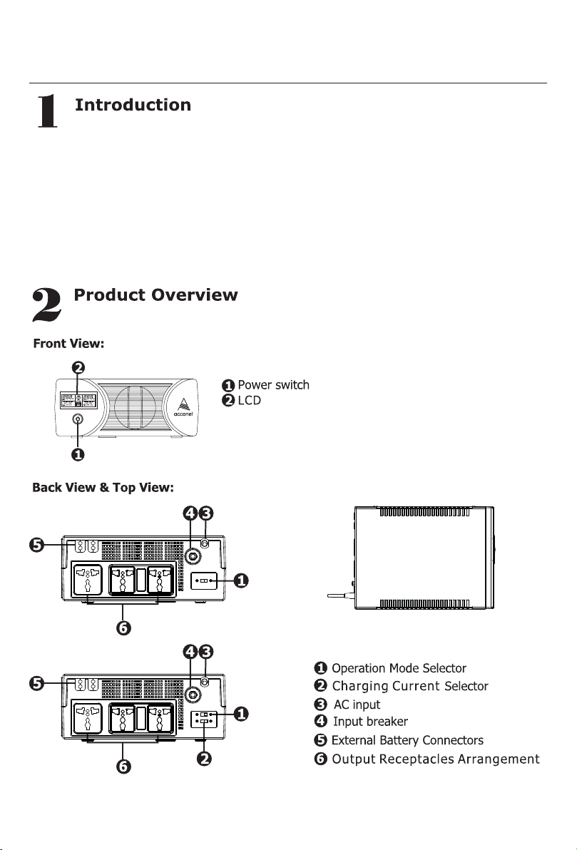
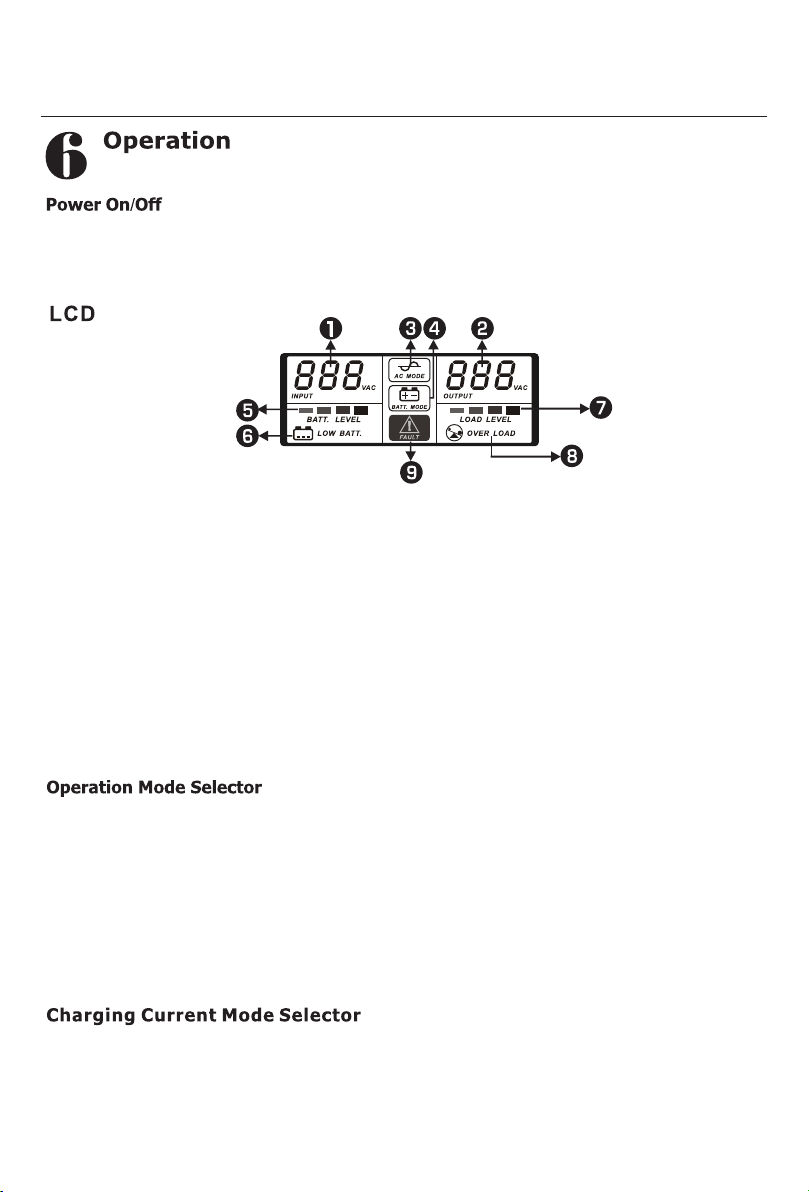
1.Input voltage
2.Output voltage
3.AC mode (unit operating in line mode, this L CD symbol will be lit)
4.Battery mode (when operating in inverter mode, this LCD symbol will be lit)
5.Battery level (Battery capacity)
6.Low battery (when battery voltage is low, this LC D symbol will be flashing)
7.Load level (Load percentage used)
8.Overload (when the load exceeds max load capacity, this LC D symbol will be
flashing)
9.Fault mode(this LCD symbol will be lit when inverter is in fault mode, such as a
short circuit or system overload)
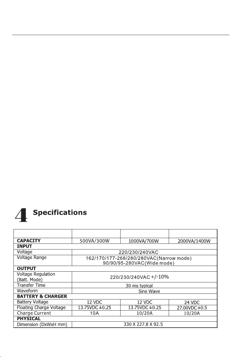
Narrow Mode: 162 V to 280 V, the unit will not switch over to battery backup if utility
power is available and the utility voltage is higher than 162 V and lower than 280 V.
Wide Mode: 90 V to 280 V, the unit will not switch over to battery backup if utility
power is available and the voltage is higher than 90 V and lower than 280 V.
a). "Narrow": setting for conventional electrical appliances such as computers, TVs etc.
as narrow mode reduces the switch over time from utility to battery backup.
b). "Wide: setting for energy saving, with lower line sensitivity and longer switch over
times during power failures.
10/20A: The maximum charging current determines the recommended battery capacity
which can be connected to the unit as it will effect charging time periods required to fully
recharge the connected batteries for example the 10A current is recommended for
100AH or lower batteries.