SUNPOWER CORPORATION
Safety and Installation Instructions - Document 001-14158 Rev **
©May 2007 SunPower Corporation. All rights reserved. Specifications included in this manual are subject to change without notice.
Safety and Installation Instructions
(United States and Canada)
1.0 Introduction
This manual provides safety and installation instructions for UL-listed
SunPower photovoltaic (PV) modules carrying the UL logo on the product label
(Figure 1).
Figure 1
1.1 Disclaimer of Liability
The installation techniques, handling and use of this product are beyond
company control. Therefore, SunPower does not assume responsibility for
loss, damage or expense resulting from improper installation, handling or use.
1.2 Underwriters Laboratories (UL) Listing Information
This product meets or exceeds the requirements set forth by UL1703 for PV
Modules. This UL Standard covers flat-plate PV modules and panels intended
for installation on buildings or those intended to be freestanding. To satisfy the
listing for this product the modules must be mounted with a rack or standoff
structure. The UL listing does not include integration into a building surface
because additional requirements may apply. This product is not intended for
use where artificially concentrated sunlight is applied to the module.
1.3 Limited Warranty
Module limited warranties are described in the SunPower warranty certificates
obtainable at www.sunpowercorp.com.
2.0
Safety Precautions
Before installing this device, read all safety instructions in this document.
•Cover all modules in the PV array with an opaque cloth or material before
making or breaking electrical connections.
•All installations must be performed in compliance with the National
Electrical Code (NEC) and any applicable local codes.
•There are no user serviceable parts within the module. Do not attempt to
repair any part of the module.
•Installation should be performed only by authorized personnel.
•Remove all metallic jewelry prior to installing this product to reduce the
chance of accidental exposure to live circuits.
•Use insulated tools to reduce your risk of electric shock.
•Do not stand on, drop, scratch, or allow objects to fall on modules.
•If the front glass is broken, or the back sheet is torn, contact with any
module surface or module frame can cause electric shock.
•Do not install or handle the modules when they are wet or during periods of
high wind.
•Contact your module supplier if maintenance is necessary.
•Save these instructions!
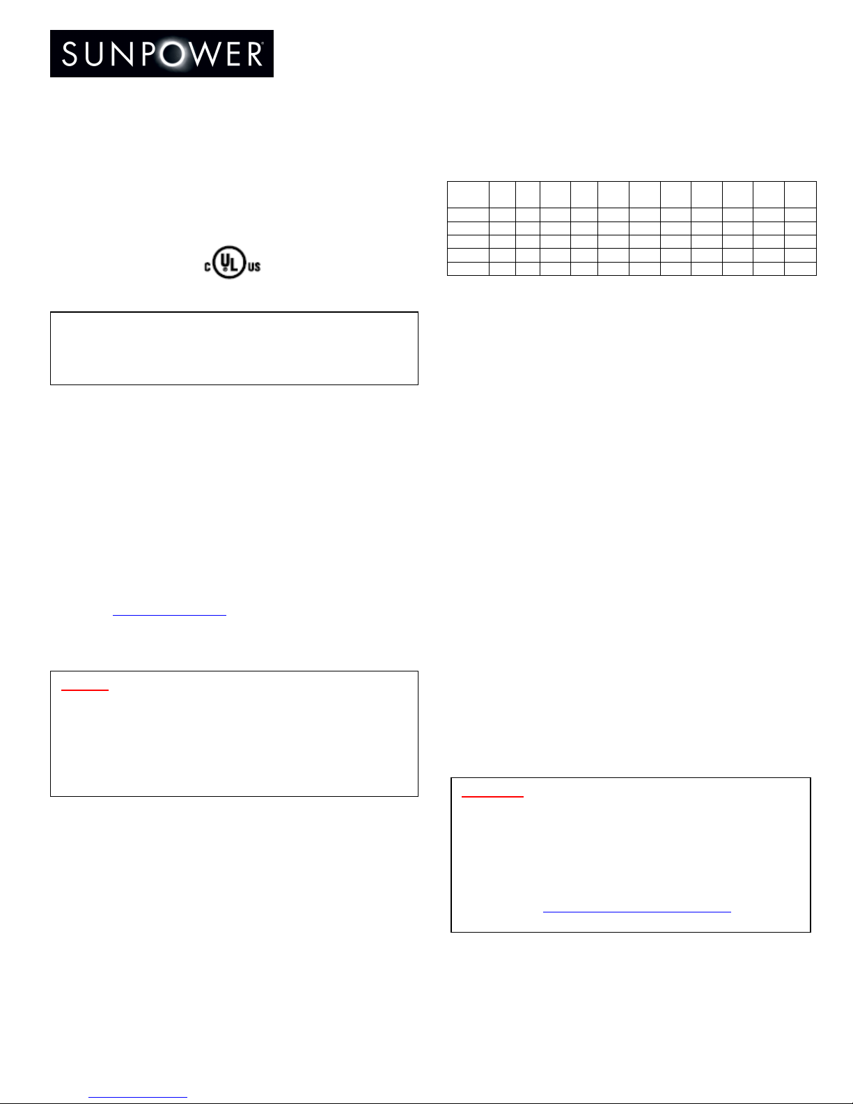
3.0 Electrical Characteristics
The module electrical ratings are measured under Standard Test Conditions
(STC) of 1 kW/m² irradiance with AM 1.5G spectrum and a cell temperature of
25º C. SunPower modules deliver specific electrical characteristics (Figure 2).
Electrical Characteristics at STC
Module Rated
Power
(W)
Power
Tol
(%)
Voltage
at Rated
Power
(V)
Curr at
Rated
Power
(A)
Open
Circuit
Voltage
(V)
Short
Circuit
Current
(A)
Max
Series
Fuse (A)
Max Sys
Voltage
(V)
Current
Temp
Coeff
(mA/°C)
Voltage
Temp
Coeff
(mV/°C)
Power
Temp
Coeff
(%/°C)C)
SPR-220-
WHT 220 +/- 8 39.8 5.53 48.3 5.95 15 600 3.5 -136.8 -0.38
SPR-215-
BLK 215 +/- 8 39.8 5.40 48.3 5.80 15 600 3.5 -136.8 -0.38
SPR-210-
WHT 210 +/- 5 40.0 5.25 47.7 5.75 15 600 3.5 -136.8 -0.38
SPR-205-
BLK 205 +/- 5 40.0 5.13 47.8 5.53 15 600 3.5 -136.8 -0.38
SPR-200-
WHT 200 +/- 5 40.0 5.0 47.8 5.4 15 600 3.5 -136.8 -0.38
Figure 2
A photovoltaic module may produce more current and/or voltage than reported
at STC. Sunny, cool weather and reflection from snow or water can increase
current and power output. Therefore, the values of Isc and Voc marked on the
module should be multiplied by a factor of 1.25 when determining component
voltage ratings, conductor ampacities, fuse sizes, and size of controls
connected to PV output. An additional 1.25 multiplier may be required by the
NEC for sizing fuses and conductors as described in the NEC Section 690-8.
3.1 Fire Rating
The module is Class C fire rated.
4.0 Electrical Connections
Modules may be connected in series and/or parallel to achieve the desired
electrical output as long as certain conditions are met. Please use only the
same type of modules in a combined source circuit.
4.1 Equipment Grounding
To avoid electrical shock, ground the frame of the module or array before
wiring the circuit using a grounding method that meets NEC requirements for
grounding solar electrical systems. SunPower recommends the following two
methods of grounding the module frame.
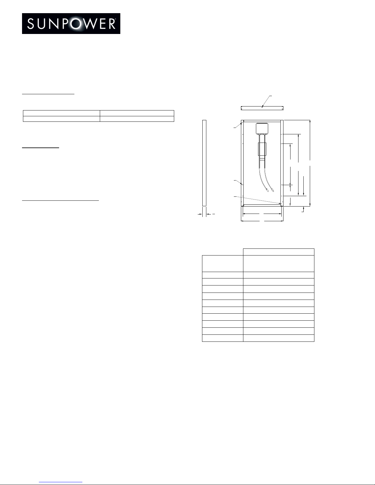
1) Attach an equipment ground conductor with stainless steel hardware at one
of the four designated 0.17grounding holes on the module frame. If an
equipment ground conductor larger in diameter than #10 AWG is necessary, a
grounding lay-in lug is required. A thread-forming 10-32 stainless steel screw
is required when using a self-drilling type screw to make the frame ground
connection. Please refer to NEC Article 690 on grounding PV arrays for
specific requirements.
2) SunPower modules can be grounded using third-party grounding washer or
clip systems provided they have been tested and certified to meet UL 467
requirements for bonding/grounding systems and are installed according to the
manufacturer’s specified instructions.
4.2 System Grounding
4.3 Series Connection
The modules may be wired in series to produce the desired voltage output. Do
not exceed the maximum system voltage indicated in Figure 2.
4.4 Parallel Connection
The modules may be combined in parallel to produce the desired current
output. Each series string or module may be required to be fused prior to
combining with other strings. Figure 2 describes the maximum fuse size
allowed. Please refer to the NEC Article 690 for additional fusing requirements.
Important! Read this instruction sheet in its entirety
before installing, wiring, or using this product in any way.
Failure to comply with these instructions will invalidate
the SunPower Limited Warranty for PV Module.
Danger! Module interconnects pass direct current (DC) and
are sources of voltage when the module is under load and
when it is exposed to light. Direct current can arc across
gaps and may cause injury or death if improper
connection or disconnection is made, or if contact is
made with module leads that are frayed or torn. Do not
connect or disconnect modules when current from the
modules or an external source is present.
Important! For optimal performance, SunPower PV modules
must only be used in configurations where the positive
polarity of the PV array is connected to ground. Failure to
comply with this requirement will reduce the
performance of the system and invalidate SunPower’s
Limited Power Warranty for PV Modules.
For more information on grounding the system correctly, visit
our website at www.sunpowercorp.com/inverters or contact
SunPower technical support at 1