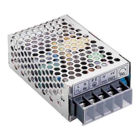
Identification:
Input:
1. Input range:
SPR-2326A6: 90~132VAC / 180~264VAC auto sensing
SPR-2326P6: Universal full rangeAC 90V ~ 264V.
2. Inrush current: When turn on input power source, there is peak current(inrush
current) running through filter capacitor of power supply. During power supply
operating, it is important not to turn off input power source and then immediately
turn on it again, otherwise, it may shorten power supply’s life.
Output:
SPR-2326A6 / SPR-2326P6 has six outputs.
Output of +3.3V plus +5V is 150W max, and output of –5V plus –12V is 12W max.
Total output is 320W max.
The loadings of each output are adjustable inside specified range, however, total
output should not exceed maximum rating.
Ex1: (Dual modules):
False!!
Output V1 V2 V3 V4 V5 V6
Voltage +3.3V +5V +12V -5V -12V +5Vsb
Load 15A 30A 20A 0.5A 1.0A 4A
Output 199.5W 240W 14.5W 20W
Total output 474W, OVER!!
Ex2: (Dual modules):
!
Output V1 V2 V3 V4 V5 V6
Voltage +3.3V +5V +12V -5V -12V +5Vsb
Load 15A 20.1A 11.5A 0.5A 0.8A 4A
Output 150W 138W 12W 20W
Total output 320W, OK!!
Ex3: (Dual modules):
!
Output V1 V2 V3 V4 V5 V6
Voltage +3.3V +5V +12V -5V -12V +5Vsb
Load 10A 3A 20A 0A 1A 4A
Output 48W 240W 12W 20W
Total output 320W, OK!!
Ex4: (Dual modules):
!
Output V1 V2 V3 V4 V5 V6
Voltage +3.3V +5V +12V -5V -12V +5Vsb
Load 19.7A 3A 20A 0A 0A 0A
Output 80W 240W --- ---
Total output 320W, OK!!
For output specification, please refer to the label on the product or visit
www.sunpower.com.tw for newly update data.
Protection:
1.Short circuit protection: When circuit shorted, power supply will shutdown and
latch.
2.Over load protection: When over 105% ~ 150% of rated loading, power supply will
shutdown and latch
3.Over voltage protection: When output voltage exceeds rated range, power will shut
down and latch.
PS-ON signal: To switch ON/OFF power supply
Logic State Function Input Voltage
PS-ON = Hi To switch Off P/S PS-ON > 2V
PS-ON = Low To switch On P/S PS-ON < 0.8V
Power fail alarm: When either power module fail or turn off, buzzer will beep, and
TTL signal will be low.
Fan fail alarm: When either power module fan fail, buzzer will beep, and TTLsignal
will be low.
Safety terms:
1. The voltage running through primary circuit could up to 2~4 times of AC input
voltage. It is forbidden for non-technicians to open the case. Contact your local
dealer for technical support if needed.
2. The temperature inside power supply may exceed 85℃during full loading, so it is
dangerous to touch power supply at this time. Be sure to keep a proper distance
between power supply and combustible material.
Trouble Shooting:
1. Buzzer beeping & power fail LED blinking:
(1)Only one module inside power set?
In normal condition, both modules should be inserted into power set. If there is
only one power module work in power set, buzzer will beep and power fail LED
will blink.
(2) Both modules is inserted in power set?
Check Module Ok Indicator on the front of power supply (see
Identification). If the LED indicator is out of light,check whether power module
is well mounting, and whetherAC power source inlet is well connected.If all well
done, and LED indicator isn’t lighted, it means this module is in trouble. Replace
a new one or contact your dealer for repairing..
2. Buzzer beeping & all indicator LED at normal condition:
Check each module’s fan.If the fan stops work,repair it or replace a new one.
3. The whole power set couldn’t work?
(1) Check whether it is well mounted.
(2) Check whetherAC power cord well connected.
(3) Check whether PS-ON is pulled low.
4.Asudden interrupt during normal working?
(1) Check whether it is over rated loading. If so, reduce loading.
(2) Check whether it is over rated voltage. If so, contactyour dealer for help.
(3) Check whether it is short circuit. If so, remove it.
(4) Check whether it is over temperature. If the environmental temperature is over
power supply’s working temperature range (0~70℃),enforce air convection. (Over
temperature protection is an optional function.)
If all of the above items were checked and power supply still cannot function normally,
please contact your local dealer for support or e-mail us: service@sunpower.com.tw.
SUNPOWER TECHNOLOGY CORP. operates a policy of continuous development. Therefore,
we reserve the right to make changes and improvements to any of the products described in
this guide without prior notice.
© SUNPOWER TECHNOLOGY CORP.All right reserved.
URL: http://www.sunpower.com.tw
July 9, 2003
Power ON/OFF switch
Buzzer reset button
Bottom module ok indicator
Top module ok indicator


