NewMar Phase Three PT-CE Series User manual

INSTALLATION/OPERATION MANUAL
PT-CE SERIES
Models:
PT-20CE, PT-40CE, PT-70CE
PT-24-20CE, PT-24-35CE
USA Headquarters:
P.O. Box 1306 • Newport Beach, CA 92663 • Phone: 714-751-0488 • Fax: 714-957-1621
Shipping: 2911 W. Garry Ave., Santa Ana CA 92704
EuroWarehouse:
Holland • Phone: +31-35-603-2494 • Fax: +31-35-603-2149
THREE STAGE SMART CHARGER/
DC POWER SUPPLY
LIMITED WARRANTY
NEWMAR warrants with the original purchase of products sold by NEWMAR, that they shall be
free from defects in material and workmanship for two years from the date of purchase.
In the event of a product failure caused by defect of material or workmanship you must return the
entire product with the original packing if possible, freight pre-paid, to the place of purchase or to
NEWMAR, 2911 W. Garry Avenue, Santa Ana, California 92704. Besides paying to send back the
product, you must include proof of purchase reflecting where the product was purchased, the date
of purchase and a written explanation of the alleged defect. If this product is determined to be
defective by NEWMAR, we will repair the product and ship it back to you without charge. If non-
repairable within 30 days, we will ship an equivalent or better replacement product or provide you
with a refund of your purchase price.
Repairs or adjustments to be made on the defective product shall be determined by NEWMAR in
its sole discretion. If you have any questions concerning this Limited Warranty, contact us at the
above address or call Customer Service at 1-800-854-3906.
ThisLimited Warranty does not apply to products that have notbeen installed properly or maintained
adequately.This Limited Warranty does not apply to damage through accident, negligence, misuse,
abuse or normal wear and tear. Further, this warranty does not cover products that have been
altered or modified from their original sale condition. For information regarding proper installation,
please consult the instructions enclosed with the product. You may contact NEWMAR or an
authorized retailer for additional installation instructions. It is your responsibility to check the product
upon receipt for any damage during shipping and to contact the carrier or shipper regarding such
damage. No person including any NEWMAR dealer, is authorized to assume any further liability
for NEWMAR beyond this Limited Warranty, in connection with the products sold by NEWMAR. A
customer’s sole and exclusive recourse against NEWMAR is this Limited Warranty, regardless of
a customer’s recourse against a seller.
THERE ARE NO OTHER WARRANTIES EXPRESS OR IMPLIED WHICH EXIST BEYOND THE
TERMS OF THIS LIMITED WARRANTY. THIS LIMITED WARRANTY IS NEWMAR’S SOLE
OBLIGATION TO YOU FOR THIS PRODUCT AND CONSTITUTES YOUR EXCLUSIVE REMEDY
UNDER THE LAW. NEWMAR SHALL NOT BE LIABLE FOR ANY INCIDENTAL,
CONSEQUENTIAL OR INDIRECT DAMAGES CAUSED AS A RESULT OF ANY DEFECT IN
WORKMANSHIP, REPAIR OR MATERIAL WORKMANSHIP REPAIR OR REPLACEMENT OF
THIS PRODUCT. NEWMAR IS NOT RESPONSIBLE FOR ANY DAMAGE THIS PRODUCT
CAUSES TO ANY OTHER EQUIPMENT OR ANY OTHER PRODUCT.
Some states do not allow limitations on how long an implied warranty lasts, so the above limitation
may not apply to you. Also some states do not allow the exclusional limitation of incidental or
consequential damages, so the above limitation or exclusion may not apply to you. Finally, this
warranty gives you specific legal rights; however, you may also have other rights which vary from
state to state.
M-PT-CE-F
All manuals and user guides at all-guides.com
all-guides.com

TABLE OF CONTENTS
SECTION TOPIC .......................................................................... PAGE
I) GENERAL INFORMATION........................................................................3
II) IMPORTANT SAFETY INFORMATION ....................................................4
III) INSTALLATION..........................................................................................7
A) Materials Provided .........................................................................7
B) Location..........................................................................................7
C) Mounting ........................................................................................7
D) Drip Shield Installation...................................................................8
E) d.c. Output Wiring ..........................................................................9
F) Multiple Unit Parallel Wiring.........................................................11
(PT-CE "Systems")
G) a.c. Input Wiring...........................................................................12
IV) OPERATION ............................................................................................15
A) Three Stage Charge Regimen.....................................................15
B) Time-Out Circuit...........................................................................16
C) Gel-Cell/Lead-Acid Selector Switch ............................................17
D) Remote Monitor Panel Option .....................................................18
E) Temperature Compensation Option ............................................18
F) Equalize Timer Option .................................................................20
G) Cooling Fan .................................................................................21
V) APPLICATION NOTES ............................................................................22
A) Start-Up ........................................................................................22
B) Constant Versus Occasional Use................................................23
C) Proper Load Sizing ......................................................................23
D) Operation with Engine .................................................................23
E) Operation as a d.c. Power Supply
or Radar Rectifier ..........................................................................23
VI) TROUBLESHOOTING .............................................................................25
VII) SPECIFICATIONS ...................................................................................27
VIII) BATTERY CARE TIPS ............................................................................29
IX) REFERENCE APPENDIX........................................................................31
I) GENERAL INFORMATION
Your Phase ThreeTM CE Series Battery Charger represents a new phase in charger
design and performance, employing "smart" switching circuitry which puts batteries
through the optimum three-step charge process, adapts for gel-cell or lead-acid
batteries, features precise voltage compensation for varying battery temperature,
is rated for continuous duty and is housed in a rugged stainless steel case.
Following is brief listing of some of the more important features/options of your
Phase Three Charger. Each is fully detailed later in this manual:
* Three step “smart” charging: bulk, absorption, float
* Gel cell/lead-acid switch selects optimum charge/float voltages based on
battery type
* Multiple output banks charge independently based on demand
* 115/230V a.c., 50-60 Hz input — can be used anywhere in the world
* Current limited — prevents damage in case of overloading
* Thermally controlled cooling fan allows continuous operation at full-rated
output
* High charge voltage time-out circuit prevents overcharge during continuous
high amperage demand
* Automatic high temperature power reduction — allows charger output in
over-temp conditions at reduced output current without complete shutdown
* Optional temperature compensation sensor fine tunes output voltage based
on battery temperature
* Optional Remote Panel allows remote monitoring of charger phase status
and manual re-initialization of charge cycle.
* Internal terminals allow installation of optional equalize timer connection.
* Use as a power supply without in-line battery; allows continued use of d.c.
powered electronics (when a.c. is available) in the event that batteries must
be taken off-line or removed.
* Rugged stainless steel case with optional-use drip shield provided
* Ignition protected per USCG CFR 183.410
Inaddition, yourPhase ThreeCharger carriesa fullone yearwarranty againstdefects
in materials or workmanship from the date of purchase. Careful attention to these
instructions should help you to enjoy years of trouble-free service.
23
All manuals and user guides at all-guides.com

II) IMPORTANT SAFETY INSTRUCTIONS
1. SAVE THESE INSTRUCTIONS -- This manual contains important safety and
operating instructions for the Phase Three CE Battery Charger.
2. Before using this battery charger, read all instructions and cautionary markings
on (1) the battery charger (2) the battery, and (3) any product powered by the battery.
3. CAUTION -- To reduce the risk of injury, charge only 6 cell (12 volt models) or 12
cell (24 volt models) gel-cell or lead-acid rechargeable batteries. Other types of
batteries may burst, causing personal injury and damage.
4. Do not expose charger to rain or spray.
5. Use of an attachment not recommended or sold by NEWMAR may result in a risk
of fire, electric shock or injury to persons.
6. To reduce the risk of damage to the electric plug and cord (if plugged into an a.c.
outlet), pull by plug rather than cord when disconnecting the charger.
7. Make sure the cord is located so that it will not be stepped on, tripped over, or
otherwise subjected to damage or stress.
8. An extension cord should not be used unless absolutely necessary. Use of an
improper cord could result in a risk of fire and electric shock. If an extension cord
must be used, make sure:
A)That pins on the plug of the extension cord are the same number, size and shape
as those on the plug of the charger;
B)That the extension cord is properly wired and in good electrical condition;
C)That the wire size is large enough for the a.c. ampere rating of the Phase Three
Charger. Refer to the SPECIFICATIONS SECTION to determine the full load input
current of your Phase Three Charger, then use the chart on the following page to
determine the correct gauge wire for any extension cord used.
RECOMMENDED MINIMUM AWG SIZE FOR EXTENSION CORDS FOR THE
PHASE THREE CE BATTERY CHARGER
Note: Does not apply to models PT-70CE and PT-24-35CE which are designed
for hard-wiring.
a.c Input Rating, Amperes Length of Cord, Feet
Equal to or but less 25 50 100 150
greater than than Size of Cord (AWG)
2 3 16 16 16 14
3 4 16 16 14 14
4 6 16 16 14 12
6 8 16 16 12 10
810 16141210
10 12 16 14 10 8
9. Do not operate the charger with a damaged cord or plug; replace them
immediately.
10. Do not operate the charger if it has received a sharp blow, been dropped, or
otherwise damaged; take it to a qualified serviceman.
11. Do not disassemble the charger; take it to a qualified serviceman when service
or repair is necessary. Incorrect reassembly may result in a risk of electric shock
and fire.
12. To reduce the risk of electric shock, disconnect the charger from a.c. source
before attempting any maintenance or cleaning.
WARNING--RISK OF EXPLOSIVE GASES
1. WORKING IN THE VICINITY OF A LEAD-ACID BATTERY IS DANGEROUS.
BATTERIES GENERATE EXPLOSIVE GASES DURING NORMAL BATTERY
OPERATION. FOR THIS REASON, IT IS OF UTMOST IMPORTANCE THAT
BEFORE INSTALLING AND USING YOUR CHARGER, YOU READ THIS MANUAL
AND FOLLOW THE INSTRUCTIONS EXACTLY.
2. To reduce the risk of battery explosion, follow these instructions and those
published by the battery manufacturer and by the manufacturer of any equipment
you intend to use in the vicinity of the battery. Review cautionary markings on these
products and on the engine.
PERSONAL PRECAUTIONS
1. Someone should be within range of your voice or close enough to come to your
aid when you work near a lead-acid battery.
2. Have plenty of fresh water and soap nearby in case battery acid contacts skin,
clothing or eyes.
3. Wear complete eye protection and clothing protection. Avoid touching your eyes
while working near a battery.
4. If battery acid contacts skin or clothing, wash immediately with soap and water. If
battery acid enters the eye, immediately flood the eye with running cold water for at
least 10 minutes and get medical attention immediately.
5. NEVER smoke or allow a spark or flame in the vicinity of the battery or engine.
6. Be extra cautious to reduce the risk of dropping a metal tool onto the battery. It
mightspark or short-circuit the battery or other electrical partand causean explosion.
7. Remove personal metal items such as rings, bracelets, necklaces and watches
when working with a lead-acid battery. A lead-acid battery can produce a short-
circuit current high enough to weld a ring or the like to metal, causing a severe burn.
8. Use the battery charger for charging gel-cell or flooded lead-acid batteries only.
It is not intended to supply power to a low voltage electrical system other than in a
starter-motor application. Do not use the charger for charging dry-cell batteries that
are commonly used with home appliances. These batteries may burst and cause
injury to persons and damage to property.
45
All manuals and user guides at all-guides.com

9. NEVER charge a frozen battery.
PREPARING TO CHARGE
1. Be sure the area around the battery is well ventilated.
2. Clean battery terminals. Be careful to keep corrosion from coming in contact with
eyes.
3. Add distilled water in each cell until battery acid reaches level specified by battery
manufacturer. This helps purge excessive gas from cells. Do not overfill. For a
battery without cell caps, carefully follow manufacturer’s recharging instructions.
4. Study all battery manufacturer’s specific precautions such as removing or not
removing cell caps while charging and recommended rates of charge.
GROUNDING AND a.c. POWER CORD CONNECTION
1. The charger should be grounded to reduce the risk of electric shock.
2. The Phase Three Charger is provided with an IEC certified a.c. power cord (except
models PT-70CE and PT-24-35CE). If, for any reason, the plug on the cord must be
changed or replaced, observe color coding of the a.c. wiring as follows:
Brown...........................................................................a.c. Hot (fused)
Blue..............................................................................a.c. Neutral
Green (or Green with Yellow Stripe)............................a.c. Ground (safety,earth)
The charger must be plugged into an outlet that is properly installed and
grounded in accordance with all local codes and ordinances.
DANGER:Never alterthe a.c.cord or plug provided, unless it is absolutely necessary
for use with the a.c. outlet which conforms to all relevant electrical codes. Any
modification of the cord must only be done by a qualified electrician. Improper cord/
outlet connection can result in a risk of electric shock.
EXTERNAL CONNECTIONS TO THE CHARGER SHALL COMPLY WITH UL
RECOMMENDATIONS AND/OR UNITED STATES COAST GUARD ELECTRICAL
REGULATIONS (33CFR183, SUB-PART I)
THE INSTALLATION AND PROTECTION OF VESSEL WIRING ASSOCIATED
WITH BATTERY CHARGERS SHALL COMPLY WITH ABYC STANDARDS E-8)
AC ELECTRICAL SYSTEMS ON BOATS, E-9) DC ELECTRICAL SYSTEMS ON
BOATS, AND A-20) BATTERY CHARGING DEVICES.
III)INSTALLATION
A) Materials Provided
The following items are provided with your Phase Three Charger (Note: Since this
manual covers several models, the provided items will differ, as noted.) Check to be
sure that these items have all been included in the packaging. For any missing
items, contact the factory or warehouse.
(1) IEC CERTIFIED a.c. INPUT POWER CORD.
(except PT-70CE and PT-24-35CE)
(1) INPUT POWER CORD CABLE CLAMP (except PT-70CE and PT-24-35CE)
(1) INPUT POWER CORD STRAIN RELIEF ( PT-70CE and PT-24-35CE only)
(1) INPUT FUSE FOR 115V a.c. APPLICATIONS (230V a.c. FUSE INSTALLED)
(1) a.c. INPUT WIRING COVER (PT-70CE and PT-24-35CE only)
(1) INPUT CONNECTOR/ADAPTOR FOR 115V a.c. INPUT SELECTION
(models PT-70CE and PT-24-35CE only)
(1) INPUT CONNECTOR/ADAPTOR FOR 230V a.c. INPUT SELECTION
(models PT-70CE and PT-24-35CE only)
(4) 1/4" RING LUGS FOR d.c. OUTPUT CONNECTION
(1) DRIP SHIELD
(4) SNAP-IN NYLON STAND-OFFS
(4) PUSH-IN NYLON FASTENERS
(1) CUSTOMER SATISFACTION/WARRANTY CARD
(1) INSTALLATION/OPERATION MANUAL
B) Location: The charger should be mounted on a wall, bulkhead or other suitable
mounting surface as close to the batteries to be charged as possible. Do not mount
the charger directly over the batteries as battery fumes may cause excessive
corrosion. The area should be well ventilated and free from excessive moisture,
exhaust manifolds and battery fumes.
Vertical mounting is preferred in order to allow the drip shield to protect the charger
from any moisture which may fall onto the charger. However, vertical mounting is
acceptable since the charger is forced-air cooled. It should not be located where
there is a possibility of debris being drawn into the unit through the fan.
If the charger is located in an extreme heat area, such as an unventilated engine
room, and the cooling fan is unable to maintain proper operating temperature, output
power will automatically be reduced to protect the charger. For maximum
performance the charger should not be located in an area of extreme high
temperature.
IMPORTANT: Although the charger is constructed of materials and in a manner
which make it highly resistive to the corrosive effects of moisture in the environment,
the charger is not waterproof. Do not mount the charger where there is a possibility
of water enteringthe unit.Evidenceofwater entry intothechargerwill void thewarranty.
C) Mounting: You will require at least (4) 1/4" screws with washers to mount the
charger, and two temporary holding screws. Note that, in addition to the four
permanent mounting holes in the flanges, there is a hole in each mounting flange
which is “keyhole” shaped. This is provided to ease vertical installation.
Make a mark on the wall or bulkhead where each of the keyhole slots will be located.
Then drive a screw about half-way in at each of these marks. Hang the charger onto
67
All manuals and user guides at all-guides.com

the bulkhead using the “keyhole” slots. Doing this will save you from having to
support the charger’s weight while you are driving in the four permanent mounting
screws. Note: The “keyhole” slots may be used for additional support screws but
they are not to be used as a permanent mounting points, by themselves.
Note: a.c. wiring for models PT-70CE and PT-24-35CE is through the bottom of the
unit. If the mounting location will make access difficult, proceed with a.c. wiring
installation before mounting the charger.
D) Drip Shield Installation: If the charger is vertically mounted in an area where
there is possibility that condensation or water leaks may occur overhead, installation
of the provided drip shield is strongly recommended. Use the four nylon stand-offs
and four nylon fasteners to install the drip shield as shown in FIGURE 1:
FIGURE 1: DRIP SHIELD INSTALLATION
Snap-in Nylon Stand-off
Drip Shield
Push-in Nylon Fastener
Note: Diagram also depicts exploded view of fan and filter assembly (which have
been factory installed). These will be discussed later in this manual. The nylon
stand-offs and fasteners will snap into place though some force may be required if
they resist.
E) d.c. Output Wiring
NOTE: (For marine applications) THE INSTALLATION AND PROTECTION OF
VESSEL WIRING ASSOCIATED WITH BATTERY CHARGERS SHALL COMPLY
WITH ABYC STANDARDS E-8) AC ELECTRICAL SYSTEMS ON BOATS, E-9)
DC ELECTRICAL SYSTEMS ON BOATS, AND A-20) BATTERY CHARGING
DEVICES.
Note: Only qualified service personnel should access the output terminals of the
charger.
Pull off the black plastic terminal cover at the bottom of the front panel to expose the
d.c. output terminals and attach d.c. wiring with ring lug connectors only.
Ring lug connectors have been provided to suit most common installations.If the
wiring for your installation is not properly matched for the provided lugs, appropriate
lugs must be obtained prior to installation.
The d.c. wire size table on this page may be used to determine the correct gauge
wire,based on the model you have andthe distancefrom the charger to the batteries.
Wire size depends on the amount of current the charger is designed to deliver, and
is unrelated to input/output voltage.
d.c. Wire Size Table:
Model Distance from Batteries, feet
51015 20
Wire Gauge AWG (mm)
20 amp #10 (6mm) #8 (10mm) #6 (16mm) #6 (16mm)
35, 40 amp #8 (10mm) #6 (16mm) #4 (25mm) #4 (25mm)
70 amp #6 (16mm) #4 (25mm) #4 (25mm) #2 (35mm)
Two typical d.c. wiring configurations are illustrated in FIGURES 2 and 3. Note: If
you are only charging one or two battery banks you may simply ignore the remaining
output terminal(s). The charger is able to deliver its full rated output through any
single bank, if necessary.
FIGURE 2: SIMPLE D.C. WIRING (PREFERRED METHOD)
Note: This diagram does not illustrate a complete system. Refer to ABYC Standards
E-8) AC Electrical Systems on Boats, E-9) DC Electrical Systems on Boats, and A-20)
Battery Charging Devices.
IMPORTANT: Install fuses at batteries per ABYC recommendations.
*
* Note: d.c. chassis grounding conductor
must not be more than one size under that
required for the d.c. charging conductors.
89
All manuals and user guides at all-guides.com

Note: This diagram does not illustrate a complete system. Refer to ABYC Standards E-
8) AC Electrical Systems on Boats, and E-9) DC Electrical Systems on Boats, and A-20)
Battery Charging Devices.
IMPORTANT: Install fuses at batteries per ABYC recommendations.
Note: If batteries are closer to charger than battery switch, wire directly to
battery posts.
It is recommended that d.c. wiring from the charger to the batteries be as direct as
possible. Line voltage loss and electronic noise interference of sensitive electronics
are possible if the charging leads are routed through a central electrical distribution
panel. Any elaborate configurations are best left to a qualified electrician.
ENSURE THAT LEADS ARE PROPERLY FUSED AT THE BATTERY. (REFER
TO ABYC RECOMMENDATIONS. SEE REFERENCE APPENDIX AT THE END
OF THIS MANUAL FOR ABYC CONTACT INFORMATION.)
Ensure that your connections are tight and that correct polarity is carefully observed
at all times. The battery posts should be free of any rust or corrosion.
IMPORTANT NOTE: EVEN MOMENTARY REVERSE POLARITY CONNECTION
MAY SEVERELY DAMAGE YOUR CHARGER. THE POSITIVE (+) TERMINAL
MUST BE WIRED TO THE POSITIVE POST OF THE BATTERY AND THE
NEGATIVE OR COMMON (-) TERMINAL TO THE NEGATIVE POST OF THE
BATTERY OR COMMON BUS.
CAUTION: Do not attempt to increase battery bank capacity by splitting the output
of one of the banks with a diode-type battery isolator. Undercharging may occur on
that output bank, as a result. If you wish to add another isolated battery bank, use of
NEWMAR’s Battery Bank Integrator is recommended. Contact the factory for details.
Be sure to replace the black plastic terminal cover to prevent accidental shorting of
the output terminals in the future.
FIGURE 3: WIRING WITH BATTERY SWITCH
*
* Note: d.c.
chassis
grounding
conductor
must not be
more than one
size under that
required for the
d.c. charging
conductors.
An Important Note about the d.c Output Fuse(s): internald.c wiringis protected by
internal d.c. output fuse(s). The current limiting circuit of the Phase Three Charger
should prevent these fuses from blowing under normal operating conditions. If the
d.c fuse(s) blow, this may indicate a reverse polarity hook-up or an internal short.
Always disconnect a.c. to the charger before checking fuses. Tocheckor replace
the d.c. fuse, the cover must be removed. To do this requires removal of four screws
from the front of the unit and three screws on each side. The d.c. fuse is mounted
on the main circuit board. Be sure to replace with the same type and value as
indicated on the fuse.
If the battery was connected to the charger backwards, the fuse should blow to
protectd.c. wiring, however damage to internal componentsmay alsohave occurred.
If the replacement fuse blows, return the charger to an electronics service
professional or to the factory for a thorough inspection. Note: The internal fuses do
not provide protection if there is a short in the wiring between the charger and the
battery. The battery is itself a power source and charging leads should be fused at
the battery per ABYC standards.
F) Multiple Unit Parallel Wiring
MultiplePT-CE series chargers may be wired inparallel, if necessary. Either identical
or different models may be paralleled (12 volt models with 12 volt, 24 volt models
with 24 volt) They are diode protected against feedback from other units and current
limiting will prevent overloading. There are two main reasons why you may wish to
wire multiple units in parallel:
1) To meet the current requirements of very large capacity battery systems and/or
large d.c. loads— If, for instance, you require 110 amps for a 12 volt system, you
may wire a PT-70CE in parallel with a PT-40CE. FIGURE 4 shows a typical wiring
schemeof this sort. Note: If the temperaturecompensation optionis used, a separate
sensor must be provided for each charger. (See section IV-E)
FIGURE 4: PARALLEL WIRING FOR LARGE CAPACITY BATTERY SYSTEMS
IMPORTANT: Install fuses at batteries per ABYC recommendations.
Note: This diagram
does not illustrate
a complete system.
Refer to ABYC
Standards E-8) AC
Electrical Systems
on Boats, E-9) DC
Electrical Systems
on Boats, and A-20)
Battery Charging
Devices.
Bank 1 Bank 2 Bank 3
PT-70CE PT-40CE
**
* Note: d.c. chassis
grounding conductor
must not be more
than one size under
that required for the
d.c. charging
conductors.
10 11
All manuals and user guides at all-guides.com
all-guides.com

2) To provide for parallel/redundant “N + 1” power system reliability — Certain
critical d.c. systems, such as those which power emergency service
communications equipment, must remain fully powered, even in the event of a
failure of one of the power supply/battery chargers. To provide this extra measure
of reliability, one more charger is wired into the system than is required for normal
operation. If, for instance, 70 amps is required for a 24 volt system, two of the PT-
24-35CE wired in parallel would normally be sufficient. To provide “N + 1”
redundancy a third PT-24-35CE is wired in parallel with the others. That way, if one
unit were to fail, the remaining two could continue to power the load until the failed
unit could be replaced or repaired. FIGURE 5 shows a typical “N + 1” wiring scheme.
FIGURE 5: TYPICAL PARALLEL/REDUNDANT “N + 1” WIRING
IMPORTANT: Install fuses at batteries per ABYC recommendations.
When wiring chargers together in parallel, remember that the wire gauge for each
charger will remain the same as if it were wired into a system by itself.
G) a.c. Input Wiring
NOTE: (For marine applications) THE INSTALLATION AND PROTECTION OF
VESSEL WIRING ASSOCIATED WITH BATTERY CHARGERS SHALL COMPLY
WITH ABYC STANDARDS E-8) AC ELECTRICAL SYSTEMS ON BOATS, E-9)
DC ELECTRICAL SYSTEMS ON BOATS, AND A-20) BATTERY CHARGING
DEVICES.
1) PT-20CE, PT-40CE, PT-24-20CE
These models are provided with an IEC certified a.c. cord which may be plugged
into the charger and a proper outlet. If the plug is not suited to the available outlet,
1) obtain an IEC cord with appropriate plug or 2) obtain the correct plug for the 2)
Note: This diagram
does not illustrate
a complete system.
Refer to ABYC
Standards E-8) AC
Electrical Systems
on Boats, E-9) DC
Electrical Systems
on Boats, and A-20)
Battery Charging
Devices.
To Critical 70 amp load(s)
Bank 1 Bank 2 Bank 3
PT-24-35CE PT-24-35CE PT-24-35CE
***
* Note: d.c.
chassis
grounding
conductor
must not be
more than one
size under that
required for the
d.c. charging
conductors.
outlet and install it on the provided IEC cord. When installing the plug, pay careful
attention to the pin wiring as follows:
Brown ....................................................................................... a.c. Hot (fused)
Blue .................................................................................................a.c. Neutral
Green (or Green with Yellow Stripe) .......................a.c. Ground (safety,earth)
As shipped from the factory, the charger is set up for 230V a.c. input. For 115V a.c.
applications you must:
1) Slide the recessed 115/230 input select switch located on the left hand side of
the charger into the proper position. Positions are identified on the front of the
charger.
2) Replace the input fuse as explained in section 3) Input Fuse Replacement, on
page 15. The correct fuse for 115V applications is attached to the hang tag on the
BATT. 1 terminal of the charger. If it is missing, see the INPUT/OUTPUT FUSE
VALUE tablein theSPECIFICATIONS section ofthis manual to determine the correct
fuse value.
A power cord cable clamp has been provided to prevent accidental disconnect of
the a.c. cord. After the plug has been inserted into the charger, snap the pre-formed
clamp around the a.c. input cable as close to the insertion point as practicable and
use a screw to fasten the clamp tightly to the wall or bulkhead on which the charger
is mounted. (See FIGURE 2 or FIGURE 3.)
Hard-wiring a.c. input
If desired, the a.c. input to your charger may be hard-wired directly to the a.c.
distribution panel. Install the charger end of the provided input cord as described
above, then cut off the plug and splice onto three conductor marine-grade cable
with crimp butt connectors, observing color codes and fuse/circuit breaker ratings
as above. For all models use minimum 16 AWG cable.
All charger wiring should be made in accordance with UL, U.S. Coast Guard
and/or A.B.Y.C. regulations and recommendations, as well as all relevant local
codes. See REFERENCE APPENDIX for sources.
fuseholder
input
connector/
adaptor
(115 or 230V)
a.c. input
terminal block
strain
relief
115V a. c. selector
Caution - Read before applying a.c. power
For all installations:
Install the appropriate 115V or 230V input
adaptor (keyed for correct orientation) from
the provided installation kit. A fuse for 230V
a.c. applications has been factory installed.
For 115V a.c. input applications:
Replace the factory installed 230V input fuse
(located beside this a.c. entry cover) with the
fuse provided for 115V use (attached to the
hang tag on BATT. 1 terminal)
– See manual for detailed a.c. wiring
instructions –
Models: PT-70CE, PT-24-35CE
FIGURE 6:
A.C. INPUT WIRING COMPARTMENT
Hot
Ground
Neutral
12 13
All manuals and user guides at all-guides.com

Models PT-70CE and PT-24-35
These models are designed for hard-wiring into the a.c. system. Input voltage
selection is made at the time of a.c. wiring installation, as follows:
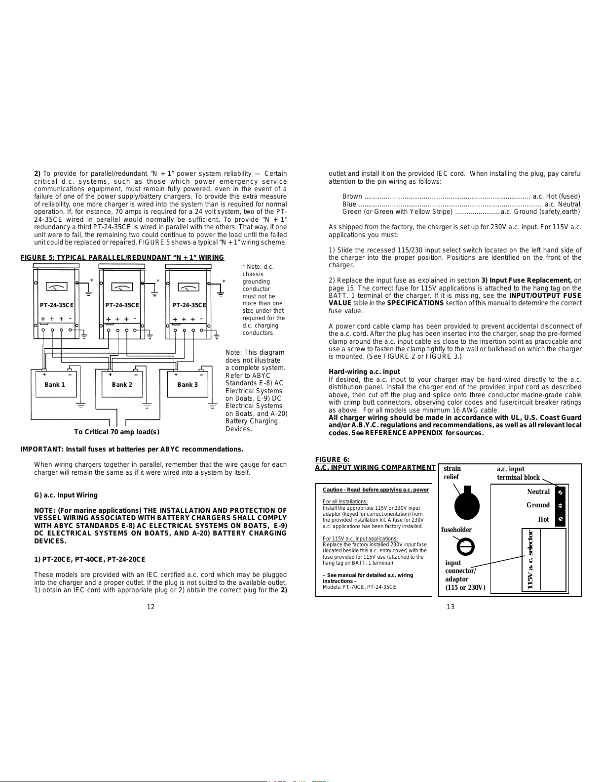
1) Read and remove the warning label (copy below) which covers the a.c. input
wiring compartment (see FIGURE 6.)
2)Select theproper connector/adaptor for your application(provided inthe installation
kit and labeled either 115V or 230V). Snap it into the adaptor receptacle. It is keyed
to ensure that it is properly positioned. Note: If the charger has previously been
used in a 115V application and must be converted for 230V use or vice-versa, the
existing connector/adaptor must be removed first. Do this by pinching hard on the
retaining tabs on either side and pulling firmly outward.
3) Snap the provided strain relief into the charger housing (oriented as shown in
FIGURE 6) and loosen the compression screw.
4) Strip about 1/4" of insulation off the ends of each a.c. input wire and feed the a.c.
input cord through the strain relief. 16 gauge (AWG) wire is sufficient for most
installations up to 20 feet in length. (Maximum gauge wiring terminal will
accommodate is 12 (AWG). Consult ABYC or USCG regulations for installations
with a.c. input wiring over 20 feet.
5) With narrow blade (1/8") flat tip screwdriver loosen the compression screw
terminals on the a.c. terminal block beside the connector/adaptor. Insert each a.c.
input wire into the appropriate terminal. The HOT and NEUTRAL terminals are the
outer terminals and are labeled on the circuit board to which terminal block is
attached. The GROUND wire is attached to the center terminal. Standard color
coding of a.c. wiring is as follows:
Europe USA
Brown........................................................Black ........................... .a.c. Hot (fused)
Blue...........................................................White ...................................a.c. Neutral
Green (or Green with Yellow Stripe)....... Green ............a.c. Ground (safety,earth)
6) Tighten the compression screw on the strain relief. Install the a.c. input wiring
cover which is provided in the installation kit. The screws which attach the wiring
cover to the charger have already been installed and will need to be removed first.
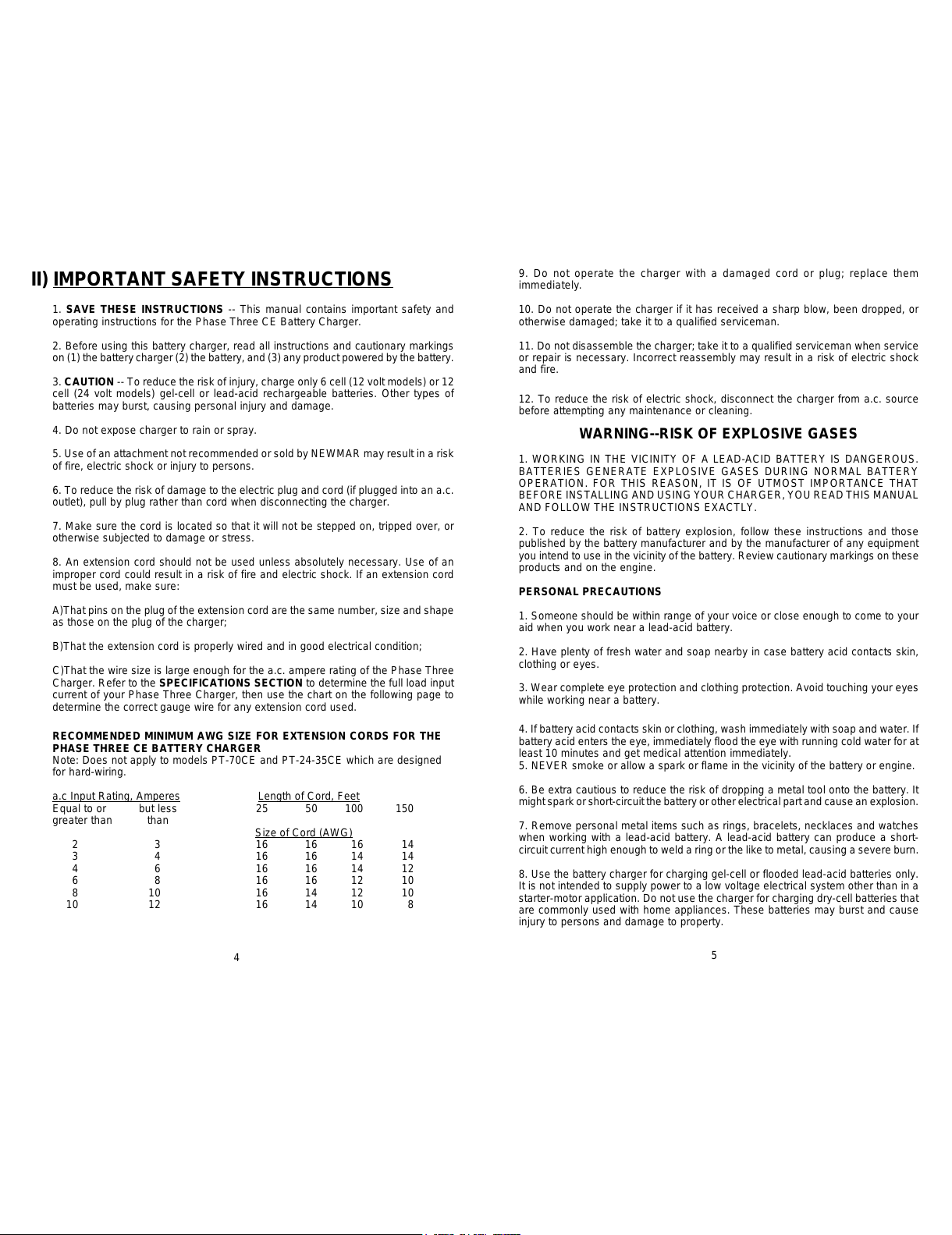
ALL MODELS: a.c. input for the charger must be plugged into an appropriate,
over-current protected three prong outlet (PT-20CE, PT-40CE and PT-24-20CE)
OR routed through a separate dedicated fuse or circuit breaker on an a.c.
distribution panel (PT-70CE, PT-24-35CE) with proper safety/earth chassis
ground in accordance with all local codes and ordinances.
Use the table below to determine the proper fuse or circuit breaker value,
depending on model and whether the application is 115 or 230V a.c.:
a.c. Fuse/Circuit Breaker Table
Model 115V a.c. 230V a.c
PT-20CE 10 amp 5 amp
PT-40CE, PT-24-20CE 15 amp 10 amp
PT-70CE, PT-24-35CE 20 amp 10 amp
CAUTION (230 V a.c applications only): If a.c. input is derived from a source
consisting of two HOT leads (phase-to-phase 230V a.c. input voltage), an
external fuse or circuit breaker must be used to protect the unfused (formerly
NEUTRAL, now HOT) lead.
3) Input Fuse Replacement
The a.c. input of your charger is protected by an input fuse. The input fuseholder is
located near the bottom of the unit on the left side (20 and 40 amp models) or on the
bottom of the unit, beside the a.c. strain relief (35 and 70 amp models). The proper
value for the input fuse is indicated on the lower left corner of the front panel. If the
input fuse needs replacing it must be replaced with the proper type and value. Use
standard or fast-blow fuses. Never use a slow-blow fuse.
Caution: Ensure that a.c. power to the charger has been disconnected before
attempting to open the fuseholder. To remove the fuse for replacement, insert a flat
tip screwdriver into the fuseholder cover and turn counterclockwise until the spring-
loaded cover releases. To replace the fuseholder cover, depress it fully into the
fuseholder and turn it clockwise until it locks into position (about a quarter turn).
Warning: Do Not replace the gray slotted cap of the fuseholder without a fuse
installed. It will not be retrievable. If this occurs, contact the factory.
All charger wiring should be made in accordance with UL, U.S. Coast Guard
and/or A.B.Y.C. regulations and recommendations, as well as all relevant local
codes. See section IX) REFERENCE APPENDIX. for sources.
IV) OPERATION
A) Three Stage Charge Regimen
The Phase Three Battery Charger features the three stage charge regimen which is
widely recommended by battery manufacturers for allowing the fastest possible
rechargetime without loss of batteries’ electrolyte (gel or liquid) which may be caused
by sustained charging at higher voltages.
This three stage regimen is initiated each time a.c. is first applied, when drained
batteries are most likely to be encountered. (This also occurs when the reinitialize
button on the optional remote panel is activated — see section D - Remote Panel
Option on page 18) The regimen proceeds as follows:
1) Bulk Charge - When batteries are significantly discharged the charger responds
initially by delivering a high amount of d.c. current, at or near the charger’s maximum
rated output, in order to rapidly replenish them. It is during this stage that charging
current is maintained at a high level as battery voltage increases. Bulk charging
continues until battery voltage reaches the “charge” voltage level (where batteries
are at about 75-80% of capacity). A current limit circuit prevents charger overload
during this maximum output stage.
2) Absorption Charge -During thissecond stageof thecharge cycle,battery voltage
is maintained at the “charge” voltage level. Output current begins to taper off as the
battery plates become saturated. Charge voltage is maintained until the current
sensing circuit detects that output current has tapered to about 5-15 % of charger
rating*. At this point the batteries are at about 95 % of full charge and the Phase
Three charger switches to the third and final stage of the charge cycle.
* Note: The absorption phase may also be ended by the time-out circuit. See section
B following for a complete explanation of the purpose and functioning of the time-
out circuit.
14 15
All manuals and user guides at all-guides.com

3) Float Charge - For extended battery life the Phase Three then automatically
switches to a lower float voltage level. This float charge keeps batteries at peak
condition without overcharging. The charger may be left in this stage for months
without attention (though periodic checks of electrolyte level in flooded batteries is
recommended).
A typical 12 volt, three phase charging cycle is illustrated below.
FIGURE 7: TYPICAL (12V) CHARGER OUTPUT GRAPH
(INTO BATTERY WITHOUT LOAD)
* =Actual charge and float voltages depend upon gel-cell/lead acid settings and/or
temperature compensation function.
** =As required by battery state of charge with an 8-10 hour maximum. Length of
maximum bulk/absorption phase duration may be increased/decreased by installer
adjustment at time of installation.
†=Intermittent loads
B) Time-Out Circuit
Batteries have a tendency to lose their electrolyte and may be damaged if they are
maintained for long periods of time in the elevated voltage of the absorption phase.
Therefore, the Phase Three Charger employs a special time-out circuit. This circuit
is initialized each time a.c. is first applied to the charger (or when the re-initialize
button on the optional remote panel is activated) and runs for a pre-set interval
before forcing the charger to go into the float (lower voltage) mode. The functioning
of the charger during this interval is as follows:
If the current demand of the batteries/load falls below 5-15 percent of the charger’s
output capacity prior to the circuit timing-out, the charger will automatically switch
to the float mode. (For instance, with model PT-40CE, the charger will drop into
float mode at about 2-6 amps output.) If demand rises to about 10-20 percent of
capacity(4-8 ampswith PT-40CE,for instance),the chargerwill returnto theelevated
output of the absorption phase. This switching back and forth between modes may
occur until the circuit times-out (8-10 hours after a.c. is first applied), after which the
Up to 8-10 hours**
*†
†
†
charger will remain at float voltage, until the circuit is re-initialized, either by turning
thecharger off and then on again or by pressingthe re-initialize button on the optional
remote panel.
Note: The PT-CE charger is able to deliver its full rated output current while in
the float mode.
Installation Note: The time-out circuit of the PT-CE charger has been set at about 8-
10hours, which is appropriate forbattery systems within the capacity range specified
on the front panel of the charger. If the charger is used with a battery system with a
capacity near (or outside) the upper or lower ranges of the specified range of the
charger, adjustment of the time-out circuit may be recommended. If the installer
wishes to make this adjustment at the time of installation, the procedure is as follows
(Caution: Ensure a.c. input has been disconnected before proceeding):
1) Remove the four screws on the front panel and three screws on each side of the
unit.
2) Remove the front cover and locate the potentiometer on the small "charger
function" plug-in printed circuit board which is labeled “TIMER ADJ.”
3) Using a small flat tip screwdriver, turn the potentiometer clockwise to increase
the amount of time the charger remains in the absorption mode before timing out, or
counterclockwise to decrease the amount of time. The approximate ranges are
illustrated below.
FIGURE 8: ADJUSTING THE TIME-OUT CIRCUIT
Note: Once the time-out circuit has put the charger into float mode, the charger
will remain in this mode. Since the Phase Three Charger is well regulated, it is
able to deliver its full rated output current in this mode and battery discharge
will not occur (provided load current does not exceed charger rating and output
wiring is properly sized).
C) Gel-Cell / Lead Acid Selector Switch
According to most battery manufacturers, the ideal charge regimen for gel-cell and
wet or flooded lead acid batteries differs somewhat.
The gelled electrolyte in a sealed battery may be lost or damaged by high voltage
and, once lost, cannot be replaced as it can with a wet lead acid battery.
Manufacturers of gel-cells usually recommend an ideal charge voltage which is
slightly lower for a gel-cell than a lead acid battery.
However, when the charger is in the float voltage mode over lengthier periods of
time, gelled electrolyte in a sealed battery is not susceptible to evaporation, as is
the non-immobilized electrolyte of a wet lead acid battery. This evaporation can be
8-10 Hours
11-13 Hours
5-7 Hours
16 17
All manuals and user guides at all-guides.com

accelerated by the applied voltage. Consequently, the ideal float voltage is slightly
higher for a gel-cell than a lead acid battery.
The ideal charge/float regimen has been programmed into the Phase Three Charger
for either sealed gel-cell or flooded lead acid batteries. Simply make the proper
selection for your battery type via the slide switch on the right side of the charger.
The switch positions are indicated on the front panel. Use a ball point pen or similar
object to slide it into the correct position.
Note: A wide variety of batteries are now available which do not conform to
conventional descriptions as “gel-cell” or “lead-acid”. You are advised to consult
the manufacturer of your particular battery as to proper charging regimen, and use
the battery type selection switch setting which most closely conforms to the
recommended voltages.
See the SPECIFICATIONS section for the actual preset charge and float voltages
for each battery type/charger model.
D) Remote Monitor Panel Option
A Remote Monitor Panel is available from NEWMAR (model RP) which will enable
you to monitor the charger’s status at-a-glance from a remote location. Red and
green L.E.D.’s indicate whether the charger is in the bulk, absorption or float phase
of the charge cycle. In addition, the panel features a re-initialize button, which,
when pressed, will cause the charger to restart the three phase cycle. This resets
thetime-out circuit(see sectionB, above)Time-out Circuit, above). Note: The charger
may not stay in the bulk or absorption mode after pressing the re-initialize button. If
batteries are at or near full charge, the charger will quickly revert to the float mode.
The panel comes pre-wired with 30' of cable and 4 mounting screws. Simply install
the panel at the desired location and insert the plug on the end of the cable into the
remote panel jack which is located on the right side of the charger. (See FIGURE
10.) The remote panel jack is identified on the front panel. Note: Inadvertently,
putting the remote panel plug into the temp compensation jack (or vice versa) will
not harm the charger.
If additional cable length is required, additional cable is commonly available from
mostelectronics supply retailers such asRadio Shack/Tandy.Request a 6 conductor
modular-to-modular line cord (part number 279-422, 25 feet long) and 6 pin modular
in-line non-reversing coupler (279-423).
E) Temperature Compensation Option
Because low battery temperature increases resistance to charging and high battery
temperaturereduces impedance, requiring a lower charge voltage, the ideal charging
voltage will vary depending on the temperature of the battery’s environment when it
is being charged.
If a charger has a fixed output voltage which is ideal at, say 72° F, that same output
may cause a battery charged in a consistently high temperature environment to be
overcharged, resulting in excessive loss of electrolyte. Conversely, if the batteries
are in a consistently cool environment, they may be chronically undercharged,
resulting in sulfation of the battery plates. Either of these two conditions will shorten
battery life.
Therefore, the Phase Three charger is designed to utilize an optional remote sensor
(available from NEWMAR; model TCS) which provides automatic temperature
compensation. The remote sensor will signal the charger to fine tune its output
voltage so that it is properly matched to the temperature of the battery/battery
environment. The adjustment rate is approximately -3 mV per cell per °F, or -5 mV
per cell per °C. (Note: The temperature compensation option is strongly
recommended for sealed, valve-regulated or gel-cell batteries.)
Caution: There are two TCS Temp sensor models. Prior to installing the TCS
Sensor, verify that you have the correct model, as the incorrect model will cause
improper output voltage. The correct TCS model for all Phase Three Chargers is
stamped with a “12” and a “24” on the metal face of the sensor. If it is not stamped,
or if it is stamped “48” contact the factory before proceeding.
The remote sensor is provided with 30' of cable. One end of the cable is plugged
into the temperature compensation jack which is located on the right side of the
charger. (See FIGURE 7.) The temp sensor jack is identified on the front panel.
If additional cable length is required, additional cable is commonly available from
mostelectronics supply retailers such asRadio Shack/Tandy.Request a 6 conductor
modular-to-modular line cord (part number 279-422, 25 feet long) and 6 pin modular
in-line non-reversing coupler (279-423).
The sensor itself should be mounted on the inside of the battery box, or more ideally,
mounted onto one of the batteries using a clamp or a small amount of silicon-type
adhesive. The sensor has a hole in the center which will accommodate a # 6 screw.
If you have access to the exterior of a wall of the battery box, you may drill a hole in
the wall of the box and run the screw through to mount the sensor onto the interior
wall. Use caution when drilling so that you do not accidentally puncture the case of
any battery inside the box.
Important note: When wiring multiple units in parallel (see section E) and using
the temperature compensation option, you must use a separate sensor for
each charger, and the sensors must be mounted close together in the same
battery box or on the same battery for proper operation.
FIGURE 9: TEMPERATURE SENSOR AND REMOTE PANEL INSTALLATION
To give some idea of the effect of the temperature compensation sensor, the chart
on the following page lists the charge/float output voltages of the charger when no
sensor is installed (or when batteries are at 72° F), and at cold (50° F) or hot (90° F)
battery temperature with temp sensor installed:
Note: This diagram does
not illustrate a complete
system. Refer to ABYC
Standards E-8; AC
Electrical Systems on
Boats, E-9; DC Electrical
Systems on Boats, and
A-20) Battery Charging
18 19
All manuals and user guides at all-guides.com

Battery Output V d.c : 12 Volt Models Output V d.c : 24 Volt Models
Temperature Charge Float Charge Float
° F ° C Gel-Cell Lead Acid Gel-Cell Lead Acid Gel-Cell Lead Acid Gel-Cell Lead Acid
50 10 14.4 14.6 14.0 13.8 28.8 29.2 28.0 27.6
72 22.2 14.0* 14.2* 13.6* 13.4* 28.0* 28.4* 27.2* 26.8*
90 32.2 13.7 13.9 13.3 13.1 27.4 27.8 26.6 26.2
* Factory pre-set voltages without temperature compensation option installed
F) Equalize Timing Option
Some manufacturers of flooded lead-acid batteries recommend a charging process
known as equalization for extended battery life. This process involves occasionally
charging a wet lead-acid battery at a very high voltage for a short period of time in
order to completely de-sulphate each of the battery plates, essentially equalizing
their voltage. The installer of the Phase Three CE charger may choose to wire in
this option at the time of installation.
Note: The equalization process is not recommended for sealed valve regulated
or gel-cell batteries.
The equalize terminals (located inside the PT charger) should be wired through a
manual or electric timer which provides a closed contact when engaged and an
open circuit when timed out (SPST — Single Pole Single Throw). Do not use a
manually operated switch for the equalize timer. This is because unless the charger
isreverted to a safe float voltage in a timelymanner, thebatteries will almost certainly
be damaged or destroyed. The timer should be a 0-12 hour type, capable of carrying
a minimum of 100 mA at 5V d.c. CAUTION: Do not install the timer in an area
requiring ignition protected equipment unless it has been certified to meet
ignition protection requirements.
The equalization circuit of the Phase Three charger boosts output voltage to
approximately 8 % above float voltage. Refer to the battery manufacturer’s
instructions when deciding the appropriate time period setting for this voltage to
achieve proper equalization, while ensuring batteries are not damaged by increased
battery temperature. This installation should only be performed by a qualified
technician.
To install the equalization timer:
1) Disconnect a.c input to the charger and disconnect charging leads.
2) Remove the PT charger cover assembly.
3) Locate the smaller “charger function” plug-in PCB which is located on the right
side of the charger. Locate “TP1” and “TP2”.
4) Route the two control wires of the timer through the bottom of the cover assembly
and solder the ends to the TP1 and TP2 board positions. (An entry hole is provided
next to the COMM terminal. Remove and discard hole plug.) Since this is low power
logic circuit wiring only, small gauge wire is acceptable (i.e., 22 AWG). If the equalize
timer wire run is greater than fifteen feet, use of twisted pair cable is recommended.
Temperature Compensation Chart 5) Ensure that the soldered ends of the control wires on the PCB cannot come into
contact with the charger housing. Use insulating material, if necessary. Replace the
charger cover assembly. Reconnect charging leads and a.c. input
G) Cooling Fan
To maximize the life of the internal components and to allow continuous operation
at full rating, the Phase Three employs an automatic integral cooling fan. This fan
operates whenever load and/or ambient temperature causes a rise in the heat sink
temperature. Its speed automatically increases/decreases in response to load/or
ambient temperature increase/decrease. Note: Under most circumstances, the fan
will be in operation when the charger is on. However, it may stop completely under
no load and/or low ambient temperature conditions.
The fan is equipped with a filter to keep debris from being sucked into the charger.
Itis recommended that this filter be removed and rinsed with clean water occasionally
to ensure adequate air flow, particularly if the charger is mounted in a dusty or
particle-filled environment. Allow the filter to dry before putting it back onto the fan.
If the filter is ever damaged, a replacement is available from NEWMAR. (Specify
part number 999-9325-2 for models PT-70CE or PT-24-35CE; for all other models
specify part number 999-9450-2. If obtaining a filter from another source specify a
1/4" thick filter medium of 30 PPI density which you can cut to size.)
Filter Cleaning/Replacement
To remove the fan filter for cleaning or replacement (see FIGURE 10):
1) Disconnect the charger from the a.c. power source.
2) Remove the drip shield by grasping it on either side and pulling firmly upward.
3) Snap off the filter retainer and remove the filter.
FIGURE 10: FAN AND FILTER ASSEMBLY
Snap-on Filter Retainer
Filter
Fan Retainer Screw
Drip Shield
Fan
20 21
All manuals and user guides at all-guides.com
all-guides.com

Fan Replacement
If the fan fails to operate when the charger is on and a load is applied, it may be in
need of replacement. Replacement fans are available from NEWMAR. (For models
PT-70CE and PT-24-35CE specify part number 999-1205-0; for all other models
specify 999-1208-0; Refer to Replacement Fan with PCB connector.)
To remove the fan for replacement:
1) Disconnect the charger from the a.c. power source.
2) Remove the drip shield by grasping it on either side and pulling firmly upward.
3) Snap off the filter retainer and remove the filter.
4) Using a phillips screwdriver remove the four fan retainer screws holding the fan
assembly in place and lift it out, taking care not to pull excessively on the fan power
leads which are attached to the internal PCB.
5) Grasp the connector at the end of the leads firmly between two fingers and snap
it out of the connector receptacle on the PCB.
6) Remove the fan from the fan plate.
Installing the new fan is simply the reverse of the above procedure.
NOTE: When installing the new fan, position it so that the direction-of-flow arrow
molded into the top of the fan housing points into the charger.
V) APPLICATION NOTES
A) Start Up
1) Before powering up your charger, check for tight electrical connections to each
battery in your system. Switch off any d.c. loads on the batteries. Apply a.c. power.
Observe the d.c. ammeter on the front panel. This meter displays the total d.c.
output of the charger, through all banks. It will give some indication of the overall
state of charge of your batteries. If the meter is reading mid-scale or higher, it is an
indication that the batteries are in a relatively low state of charge. The charger,
sensing this, is supplying high current to the batteries. If the meter needle is at or
near the bottom of the scale the batteries are at or nearing full charge.
2) Apply a load to the charger by switching on some lights, a pump or some other
d.c. appliance. Observe the charger meter. It should read approximately the same
as the expected current draw of the appliance. As current is demanded from the
battery system, the charger will automatically increase its output in response to the
increased load demand. When load current exceeds 10-20 % of the charger’s rated
capacity, the charger will go into the absorption mode and remain there until current
drops below 5-15 % of capacity or until the time-out circuit cycle is complete.
Note: The Phase Three Charger is self-limiting and will rarely blow an input fuse. If
the input fuse should blow upon first application of power, disconnect a.c. power to
the charger and consult the TROUBLESHOOTING section of this manual.
If the input fuse does need replacing, be sure to replace it with the same type and
value for continued protection. The fuse value is specified on the lower left hand
corner of the charger front panel.
B) Constant Versus Occasional Use
In general, it is recommended that the charger be left connected continuously to the
a.c. distribution system so that it will be in operation whenever a.c. is available. This
will maintain batteries at peak voltage and will automatically compensate for the
natural self-discharge of the battery system. When a load is applied to the battery
system the charger’s output will automatically increase to supply the current which
would otherwise draw battery voltage down. Repeatedly allowing batteries to
become completely discharged before recharging will greatly shorten their
life. Leaving the charger on continuously will prevent this.
While the output regulation of the charger will minimize battery gassing and water
loss, monthly checks of the electrolyte level (for wet lead acid batteries) are still
strongly recommended. Some water loss is an inevitable aspect of the charging
process, and maintaining the correct electrolyte level in your batteries is the most
important thing you can do to assure their maximum performance and long life.
C) Proper Load Sizing
The Phase Three Charger is rated for continuous duty (e.g., the PT-40CE can deliver
up to 40 amps continuously, 24 hours a day, seven days a week). While the charger
cannot be damaged by overloads that exceed this continuous rating, excessive
load demands may draw battery voltage down faster than the charger can resupply
it. If battery voltage continues to drop and the output current is at maximum while
the charger is in service, check to see that your average d.c. loads are not exceeding
the charger’s rated output. If they are, you may wish to consider adding another
charger in parallel to provide sufficient power for your requirements. (See section
III) E) Multiple Unit Parallel Wiring.)
D) Operation With Engine
It is perfectly acceptable to allow the charger to remain on when the engine is
started and while it is running. The current limit feature of the Phase Three Charger
will protect against any damage due to the high current demands of engine cranking.
Output diodes will prevent any back-feed of current into the charger from the
alternator while the engine runs.
As the alternator starts to charge the battery, the charger output will decrease.
When the battery voltage exceeds the rated output voltage of the charger it will shut
off and stay off as long as the batteries are in this high state of charge. If the battery
voltage should drop below the charger’s rated output voltage it will automatically
return to service.
E) Operation as a d.c. Power Supply (stand-alone d.c. power source) or Radar
Rectifier
Mostbattery chargersare notsuitable for powering electronic devices directly, without
a battery attached to the output, as the high ripple and pulsing d.c output ( i.e.,
rectified a.c. output) can interfere with the operation of the device. The Phase Three
22 23
All manuals and user guides at all-guides.com

charger is different. It employs a circuit that produces an extremely well-filtered d.c.
output. Therefore the charger is able to power virtually any d.c. powered device
(within the unit's rating) without the battery attached in-line (if, for instance, the
battery must be removed for any purpose and a.c. is still available). All but the most
sensitive d.c. powered electronic devices will function as normally as if powered by
a battery. In addition, the current limiting circuitry enables the charger to handle the
high start-up surges associated with inductive loads, such as d.c. motors in radar
sets.
INSTALLATION NOTES
VI) TROUBLESHOOTING
CONDITION
A. Batteries not coming up
to full charge. 1. Extremely discharged
batteries requiring long
recharge time.
1. Turn off all d.c. loads
and allow charger 24-48
hours to recharge
batteries.
POSSIBLE CAUSE SOLUTION
2. Charger limiting its
output due to overload or
over temperature
conditions.
2. Reduce d.c. load and/or
determine cause of over
temperature state (See
section III B, “Location”)
3. Fan not operating
properly, or filter clogged,
causing charger to protect
against over-heating by
reducing power output
3. Clean or replace
clogged fan filter or
replace fan if necessary
B. Charger continues to
charge at 3 amps or more-
-does not taper back in
charge.
1. d.c load still connected
to batteries. (Not a
problem condition)
1. Turn off main battery
switch to d.c electrical
panel or turn off all d.c.
loads if you wish to
confirm charger will
output minimal amperage
to fully charged batteries.
2. Check for shorted cell
in all wet lead-acid
batteries using a
hydrometer. Replace
battery if cell is shorted.
Refer to manufacturer for
testing maintenance-free
batteries.
2. Bad cell in one of the
batteries to which the
charger is connected.
C. Charger does not
charge. 1. Blown input fuse. 1. Replace fuse with
another of correct value.
Check to see if a.c input
select switch is in proper
position. Check to see if
input fuse value is correct
for input a.c voltage.
2. Charger is not receiving
a.c. input voltage or is not
receiving correct a.c. input
voltage.
2. Using a voltmeter,
confirm a.c. input voltage,
check input connections.
Confirm a.c. input select
switch is in correct position
or correct a.c. connector/
adaptor is installed.
Warning: Do Not replace the gray slotted cap of the fuseholder without a fuse
installed. It will not be retrievable. If this occurs, contact the factory.
24 25
All manuals and user guides at all-guides.com

CONDITION POSSIBLE CAUSE SOLUTION
VI) TROUBLESHOOTING (cont.)
3. Charger output is not
properly connected to
batteries.
3. Refer to d.c. wiring
installation diagram for
proper connection to
batteries.
4. Blown output fuse 4. Replace with another of
correct value (see section
III D, “d.c. output Wiring”)
5. Defective charger. 5. Return for analysis/
repair by servicing dealer
where charger was
purchased or contact
NEWMAR for Return
Authorization Number.
D. Charger repeatedly
blows input fuse with no
batteries connected.
Internal short. Same as above.
E. Reverse polarity
connection to charger has
caused charger to stop
charging.
d.c. Output fuse and
possibly other
components blown.
Replace output fuse with
another of correct value. If
fuse again blows, return to
servicing dealer or contact
NEWMAR for Return
Authorization Number.
F. High output voltage
measured across charger
output terminals.
1. Batteries not connected
to charger. It is normal to
read 1/2 volt higher across
any output bank when no
batteries are connected.
1. Check for tight
connection of charging
leads from charger to
batteries.
2. Equalize function
activated 2. Check to verify proper
installation and operation
of equalize timer
G. Charger will not stay in
bulk/absorption mode
when re-initialize button
on remote panel pressed
Batteries at or nearing full
charge (Not a problem
condition)
Verify proper operation by
pressing reinitialize button
(on optional remote panel)
and applying a large d.c.
load
C. Charger does not
charge. (continued)
VII) SPECIFICATIONS
INPUT RANGE (ALL MODELS): 85-135/170-270V a.c. (via selector switch or a.c.
input connector/adaptor); 47-63 HZ (automatic)
Derate Models, PT24-20CE and PT-40CE from 560 watts @ 95V a.c. to 500 watts
@ 85V a.c.
OUTPUT BANKS (ALL MODELS): 3
OUTPUT VOLTAGES WITHOUT TEMPERATURE COMPENSATION OPTION:
12 VOLT MODELS 24 VOLT MODELS
Charge Float Charge Float
Setting @ 50 % load @ .1 amp load @ 50 % load @.1amp load
Gel-Cell 14.0V d.c. 13.6V d.c. 28.0V d.c. 27.2V d.c.
Lead Acid 14.2V d.c. 13.4V d.c 28.4V d.c. 26.8V d.c.
TEMPERATURE COMPENSATION: - 3 mV per cell per ° F
- 5 mV per cell per ° C
TEMPERATURE RATINGS:
-40°C to + 60°C; Derate linearly from 100 % @ 50°C to 75 % @ 60°C
PROTECTION: Input fuse; Output fuse for reverse polarity protection; Current
limiting; Automatic high temperature power reduction; Time and load controlled
high rate charge circuit; Ignition protected
Model Input Amps Output Weight
115/230V Volts Amps (Cont.) Lbs. Kg.
PT-20CE 4.3 / 2.2 12 20 11 5
PT-40CE 8.5 / 4.3 12 40 12 5.5
PT-70CE 16 / 8 12 70 24 10.9
PT-24-20CE 8.5 / 4.3 24 20 12 5.5
PT-24-35CE 16 / 8 24 35 24 10.9
INPUT/OUTPUT FUSE VALUES:
Model a.c. Input Fuse d.c. Output Fuse
115V a.c 230V a.c.
PT-20CE AGC-6 AGC-3 (1 ea.) ATC-30
PT-40CE ABC-12 AGC-6 (2 ea.) ATC-30
PT-70CE ABC 20 ABC-12 (1 ea.) HBO-100
PT-24-20CE ABC-12 AGC-6 (1 ea.) ATC-30
PT-24-35CE ABC-20 ABC-12 (2 ea.) ATC-30
26 27
All manuals and user guides at all-guides.com

CASE DIMENSIONS: INCHES (CENTIMETERS)
MODEL DIAGRAM REFERENCE
ABC DE FGHIJ
PT-20CE 9.7 15.25 9.5 1.94 7.78 1.97 14.12 8.7 5.26 4.04
PT-40CE (24.6) (38.7) (24.1) (4.9) (19.8) (5.0) (24.6) (35.9) (13.4) (10.3)
PT-24-20CE
PT-70CE 12.25 18.33 12.0 2.36 8.78 3.22 17.15 11.13 7.75 6.73
PT-24-35CE (31.1) (46.6) (30.5) (6.0) (22.3) (8.2) (42.9) (27.8) (19.4) (17.1)
VIII) BATTERY CARE TIPS
Regular maintenance and proper care will assure you reliable service from the most
depended upon and sometimes most neglected items, your batteries and battery
charger.NEWMAR batterychargers aredesigned tokeep your batteries fully charged
but your batteries also need proper regular maintenance to provide a maximum life
of service.
ALWAYS READ AND FOLLOW THE BATTERY MANUFACTURER’S INSTRUCTIONS
Battery Installation
Batteries must be securely mounted to prevent them from falling over when the
vehicle or boat is in motion. A loose battery can do serious damage. Batteries should
be mounted in a battery box to contain any acid spill. Batteries give off a certain
amount of hydrogen gas when they are charging. When concentrated, this gas is
highly explosive. Therefore make sure they are in an accessible place with adequate
ventilation for any hydrogen gas discharge.
Cleaning Batteries
Dirt and electrolyte salts can build up on the top of your batteries. This accumulation
conducts electricity stored in the battery and can cause the battery to discharge by
itself. Therefore, at least twice a year, it is a good idea to disconnect the battery
cables and scrub the battery with a baking soda solution. Rinse with fresh water
and dry with a clean cloth.
You may wish to purchase a set of terminal post corrosion prevention rings. These
are alkali-saturated felt rings that slip over the battery post to reduce corrosion. Do
not apply grease to any part of the battery terminals, but you may use an occasional
light spray of silicone lubricant.
Routine Checks and Maintenance
Batteries should periodically be “exercised” (slowly discharged and then recharged)
to keep them in top condition. New batteries may need to be exercised before they
will be capable of their full rating.
If your batteries are not the sealed type, distilled water should be added to them
whenever needed. The electrolyte should cover the plates by about 1/2", allowing a
small air space at the top. Do not fill the cells up to the filler cap as this could cause
the battery to sputter out electrolyte when it is being charged. Only distilled water
should be used never plain tap water. Tap water contains chemicals and elements
that can alter the properties of the electrolyte, including specific gravity. Some
chemicals may also create an insulating coating on the battery plates which will
retard current flow.
The rate that water is lost by the battery is dependent on several factors; battery
condition, ambient temperature, battery use, charge voltage, etc. It is normal for
batteries which are not maintenance-free to require topping off about once a month.
A battery’s state of charge may be monitored by checking the specific gravity or by
open circuit voltage. You may use the following table to evaluate the condition of
your batteries:
28 29
All manuals and user guides at all-guides.com

BATTERYCONDITIONTABLE
Specific Gravity
Measured by State of
Hydrometer Open Circuit Voltage Discharge @ 80° F
12 Volt System 24 Volt System
1.265 12.6 or more 25.2 or more Fully Charged
1.225 12.4 24.8 25 % Discharged
1.190 12.2 24.4 50 % Discharged
1.155 12.0 24.0 75 % Discharged
1.120 11.7 or less 23.4 or less 100 % Discharged
*Note: Wait at least 5 minutes after charging or discharging before checking
specific gravity or open circuit voltage. The battery’s voltage needs to stabilize in
order to get an accurate reading.
Troubleshooting Your Battery System
If your battery will not accept or hold a charge, one of the following conditions may
exist:
1. A BAD BATTERY. You may have a battery with an open or shorted cell, a battery
without any “life” left. Check by charging the battery until all cells have a specific
gravity of 1.225 or greater at 80° F. If you are unable to obtain 1.225 in each cell,
replace the battery.
2. A BAD BATTERY CHARGER. If the battery open circuit voltage is low and/or the
hydrometer indicates your batteries are low, the battery charger should be providing
current to the batteries. If it is not, check the input fuse and check to see that you
have charging voltage on the output with no battery attached. Note: You will not get
an accurate voltage reading on the output of the charger with no batteries attached.
This is checked merely to ensure that you do not have an open circuit on the output.
The battery charger has a thermal power reduction circuit to protect the charger
from overheating. If you suspect this is the case, refer to the INSTALLATION section
for information about proper charger location. See also Cooling Fan on page 21.
3. ELECTRICAL LEAKAGE. You may have a previously unsuspected source of
current drain from the battery. To check for a leakage of this sort, disconnect the
battery ground cable and connect an ammeter between the negative battery post
and ground. If you have a reading over .1 amp, there is a source of current drain
from the batteries which must be located and removed.
IX)REFERENCEAPPENDIX
* For more information about boat wiring to conform to U.S. Coast Guard regulations,
write to:
Superintendent of Documents Request : 33 CFR 183 Subpart I
Government Printing Office
Washington, DC 20402
*For information about American Boat and Yacht Council recommendations for
boat wiring, write to:
American Boat and Yacht Council
3069 Soloman’s Island Road
Edgewater, MD 21037
Request: Standards and Recommended Practices for Small Craft.
AC systems: Section E8
DC systems: Section E9
A-20: Battery Charging Devices.
* For additional installation instructions, refer to:
ANSI NFPA 302
30 31
All manuals and user guides at all-guides.com
all-guides.com
This manual suits for next models
5
Table of contents
Other NewMar Power Supply manuals

NewMar
NewMar MDP-25 User manual

NewMar
NewMar Commander II Series User manual

NewMar
NewMar Centurion CR48-10 User manual

NewMar
NewMar C2R-2000 User manual

NewMar
NewMar PM-12-40A PM Series User manual

NewMar
NewMar Centurion II User manual

NewMar
NewMar Centurion III C3RS-48-124 User manual

NewMar
NewMar PT-20CE User manual

NewMar
NewMar RM2048HE User manual

NewMar
NewMar POWER-PAC User manual