manuals.online logo
Brands
  1. Home
  2. •
  3. Brands
  4. •
  5. C-TEC
  6. •
  7. Power Supply
  8. •
  9. C-TEC BF560-12 User manual

C-TEC BF560-12 User manual

FIRE ALARM
ancillaries
WARNING: THIS PSU MUST BE INSTALLED AND MAINTAINED BY A SUITABLY SKILLED AND TECHNICALLY COMPETENT
PERSON. THIS PSU IS A PIECE OF CLASS 1 PERMANENTLY CONNECTED EQUIPMENT AND MUST BE RELIABLY EARTHED.
SW1
THERM
PL2
DISPLAY
FAULT RELAY
NC COM
NO
THIS
WAY UP
+
+
-
-
CONN5
+V
BATTERY
0V
+V
OUTPUT
0V
Battery Connector
(CONN5)
12 V, 7 AH
CONN4
Battery
Fuse (F2)
F2
1234
ON
Exposed live parts under cable cover.
Isolate first before removing the small cable cover.
No user serviceable parts under cover.
HAZARDOUS VOLTAGES LED (Red Steady)
When lit red, hazardous voltages
are present under the cover
.
Mains Input 230 V, 50/60 Hz, 0.4 A
L = Live, N = Neutral, = Earth
Terminate mains cable to CONN1.
PL3
Supply Output (CONN5)
12 Vd.c
. nominal
N
L
CONN1
Table 1 - PSU Status LED (Amber)
Red Wire
Black Wire
Mains Fuse (F1)
T 1 A H 250 V, 20 mm ceramic,
T=Time Delay, H=High Breaking Capacity
0V
See Table 4 - Technical Specification
overleaf for further details
General Fault Relay (CONN4)
1 A @ 30 Vd.c.
COM
NC
NO
Relay Fault-Free State
Incoming Mains Cable
This cable must be segregated from other cables and only
enter the panel through the top right-hand drill outs.
(Must be externally fused to ≤ 6 amps)
PSU Earth Distribution Strap
DO NOT operate the PSU without first connecting
this strap to the base earth distribution post.
3 A MINI
®
automotive
blade fuse
0V
CONF
INPUT
CHG
INHB
CONF
OUT
CONN6
CHG INHB (CONN6)
Connect to 0 V to
inhibit battery charger.
CONF INPUT/OUT (CONN6)
Configurable Input/Output.
For OEM use. Do not connect.
THERM (PL3)
Battery Thermistor Connector. Optional BF322 PSU
Remote Battery Te mp. Sensor available at c-tec.com.
1234
ON
DIP S/W 1 = For OEM use. OFF (DOWN) = Defaults.
DIP S/W OFF (DOWN) ON (UP)
2
3
4
Battery Resistance
Threshold 720 mOhm
Battery Resistance #2
Threshold 3 Ohm
Battery Charge Rate #2
0.2 A (3.2 Ah)
Battery Charge Rate
0.7 A (3.2 Ah to 12 Ah)
Battery Fitted Battery Not Fitted #2
Table 2 - DIP Switch Settings
+V
FLASHES LED STATUS (LED Off = Normal)
1
2
3
Mains Failure
Battery Voltage Low (≤11 .5 V)
Battery Voltage Critical (≤11 V)
Charger Failure
Not Used (previously used to indicate Charger Healthy)
Battery Not Fitted selected (indicates DIP S/W 4 position)
Battery Resistance Fault (level set by DIP S/W 2 position)
Output Over Voltage (>15 V)
4
5
6
7
8
Battery Charger Inhibited (Warning only - Not a fault)
Steady
1234
ON
DIP SWITCH
(APPROVED
SETTINGS)
DIP SWITCH
(DEFAULT
SETTINGS)
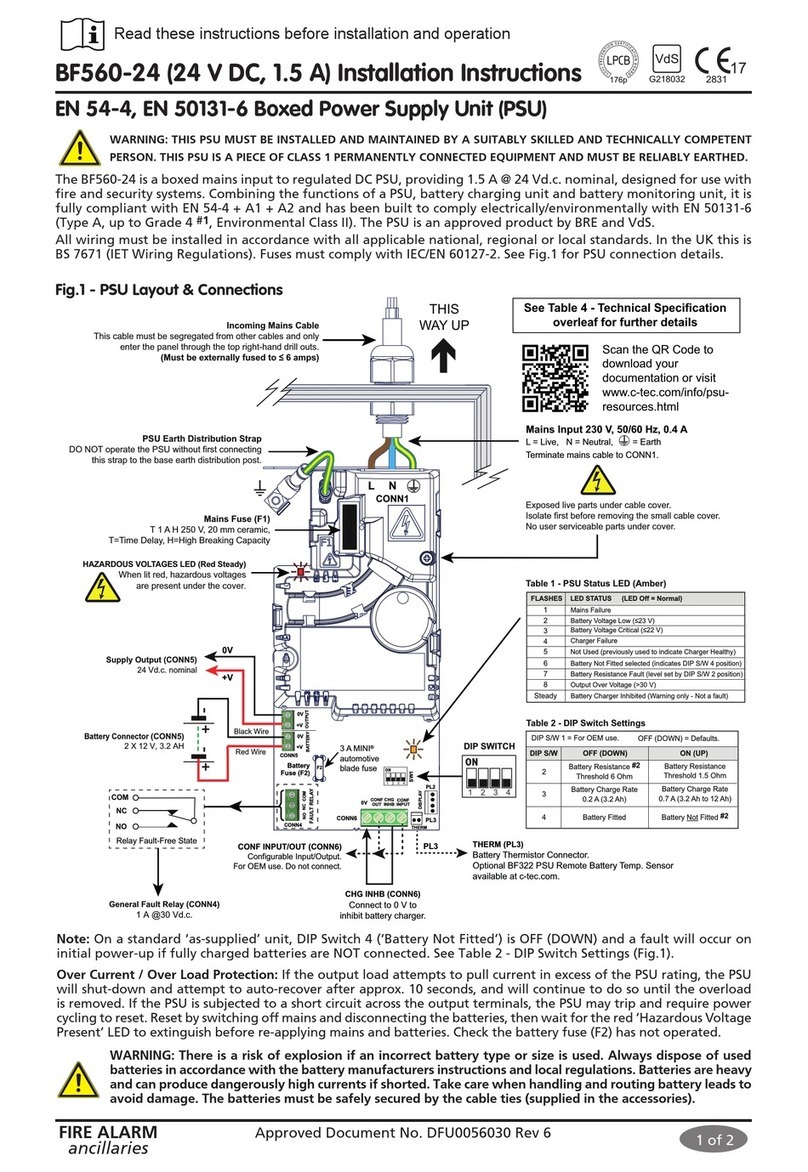
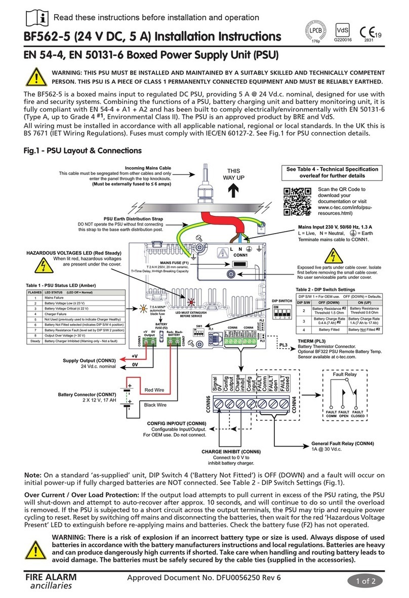
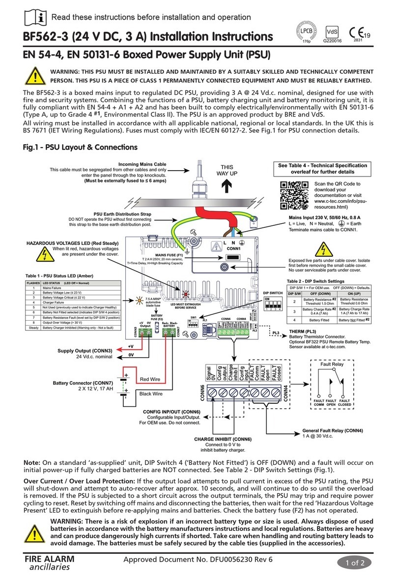
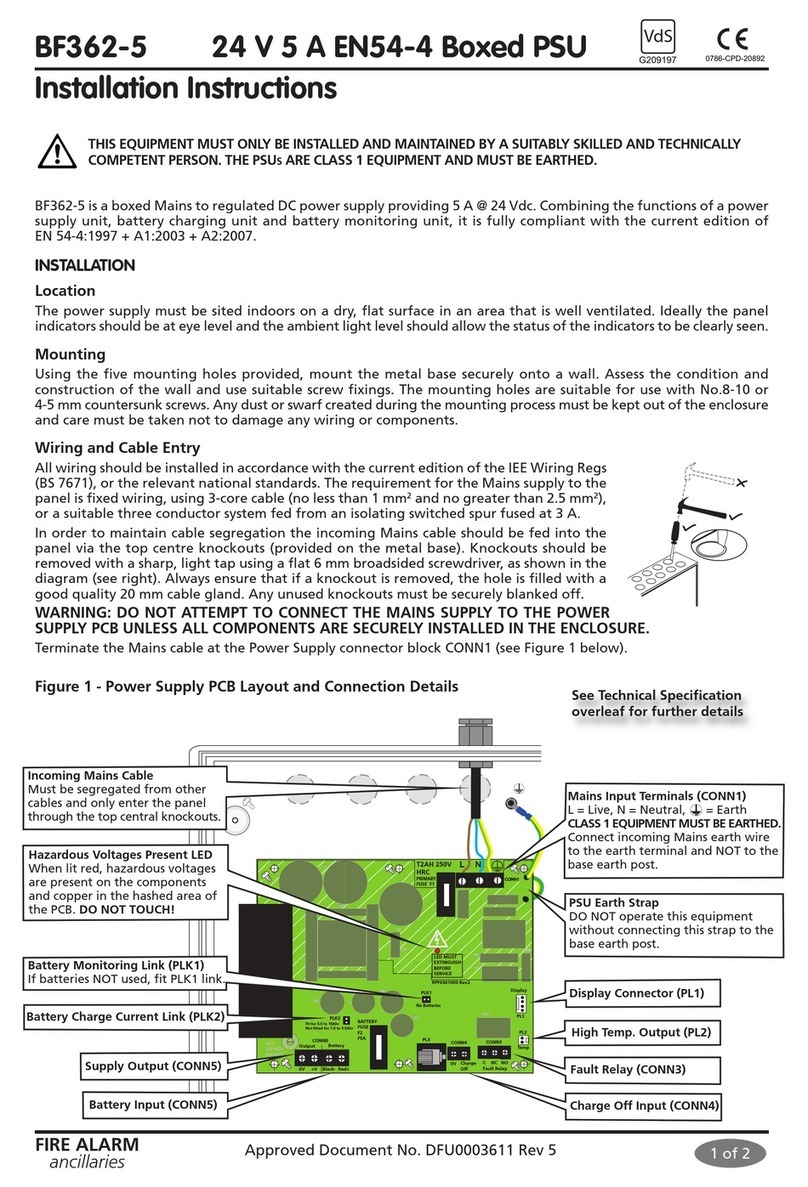
The BF560-12 is a boxed mains input to regulated DC PSU, providing 2 A @ 12 Vd.c. nominal, designed for use with
fire and security systems. Combining the functions of a PSU, battery charging unit and battery monitoring unit, it
is fully compliant with EN 54-4 + A1 + A2, EN 62368-1 and has been tested to comply electrically/environmentally
with EN 50131-6 (Type A, up to Grade 4 #1, Environmental Class II). The PSU is an approved product by BRE and VdS.
All wiring must be installed in accordance with all applicable national, regional or local standards. In the UK this is
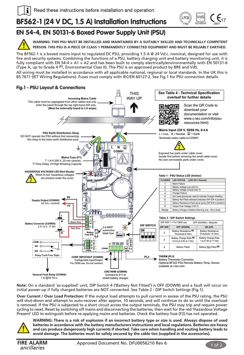
BS 7671 (IET Wiring Regulations). Fuses must comply with IEC/EN 60127-2. See Fig.1 for PSU connection details.
The requirement for the mains supply to the PSU is fixed wiring (≥1.0 mm2, <2.5 mm2), either using 3-core cable, or a
suitable three conductor system fed from an isolating switched fused spur at 3 A, or a 6 A Type B circuit breaker to IEC/
EN 60898-1. The mains supply must be exclusive to the PSU and be reliably earthed at the indicated earthing point.
HINT: As an alternative to a switched fused spur, a double-pole isolating switch with 3 mm air gaps on the contacts
& switching L & N only, may be used in the mains feed from the Main Distribution Board to the PSU, providing it
meets the appropriate wiring regulations.
1 of 2
BF560-12 (12 V DC, 2 A) Installation Instructions
EN 54-4, EN 50131-6 Boxed Power Supply Unit (PSU)
Fig.1 - PSU Layout & Connections
2831 17
VdS
G218032
176p
Over Current / Over Load Protection: If the output load attempts to pull current in excess of the PSU rating, the PSU
will shut-down and attempt to auto-recover after approx. 10 seconds, and will continue to do so until the overload
is removed. If the PSU is subjected to a short circuit across the output terminals, the PSU may trip and require power
cycling to reset. Reset by switching off mains and disconnecting the battery, then wait for the red ‘Hazardous Voltage
Present’ LED to extinguish before re-applying mains and battery. Check the battery fuse (F2) has not operated.
Note: On a standard ‘as-supplied’ unit, DIP Switch 4 is OFF (DOWN) and a fault will occur on initial power-up if a
fully charged battery is NOT connected. See Table 2 - DIP Switch Settings (Fig.1).
WARNING: There is a risk of explosion if an incorrect battery type or size is used. Always dispose of used
batteries in accordance with the battery manufacturers instructions and local regulations. Batteries are heavy
and can produce dangerously high currents if shorted. Take care when handling and routing battery leads
to avoid damage. The battery may be safely secured by using cable ties if required.
Read these instructions before installation and operation
22
0832
Scan the QR code to download
your documentation or visit:
https://www.c-tec.com/info/psu-
resources.html
#1 Additional tamper protection required #2 Non-certified setting
Approved Document No. DFU0056020 Rev 7 01/06/22
Table 4 - Technical Specification
POWER SUPPLY SPECIFICATION: BF560-12 (12 VDC, 2 A)
Mains supply voltage (a.c.): 230 V∿, 50/60 Hz. Rated current: 0.4 A r.m.s.
Maximum output current: 2A (battery charger disabled)
Output current / power rating:
1.8 A continuous ‘Imax a’ if DIP Switch 3 OFF (DOWN) #2
1.3 A continuous ‘Imax a’ if DIP Switch 3 ON (UP)
Taking a load current greater than ‘Imax a’ will temporarily reduce the battery charge current
2 A ‘Imax b’, battery charger turned off via CONN6
‘Imin’ = 0 mA
Output voltage: 10 V (‘V min’) to 15 V (‘V max’) ± 2% <150 mV ripple pk-pk
Battery characteristics:
Discharge cut-off: 10.5 V ± 2%
Float charge voltage: 13.65 V ± 1% @ 20°C
Battery temp. compensation: -18 mV / °K
Maximum approved VRLA battery size: Up to 7 Ah
Battery charge capacity (C): 3.2 Ah up to 12 Ah (battery charged to 80% of capacity in 24 hrs)
Maximum internal battery resistance ‘Ri max’: 3 Ω if DIP Switch 2 OFF (DOWN) #2 720 mΩif DIP Switch 2 ON (UP)
CONNECTIONS
Mains Input (CONN1): Mains supply input terminals: Live, Neutral & Earth. 1 mm2to 2.5 mm2cable size.
Supply Output (CONN5): Output for auxiliary equipment. 1 mm2cable size, <30 m cable length (screened cable must be used).
Battery Connector (CONN5): Connection to the VRLA battery. 1 mm2cable size.
Fault Relay (CONN4): Isolated changeover relay output, rated 1 A @ 30 Vd.c., 1 mm2cable size <30 m cable length (screened cable must be used).
CONN4 should not be used for compliance with EN 50131-6, PL2 provides serial data for all fault signals.
Battery Charge Inhibit (CONN6):
Connect to 0 V to inhibit battery charger. 1 mm2cable size.
CONF Input / Output (CONN6): For OEM use
PL2: Serial Data Connector. Protocol available via C-TEC Technical. Optional BF423 configurator tool available at c-tec.com.
PL3: Battery Thermistor Connector. Optional BF322 PSU Remote Battery Temperature Sensor available at c-tec.com.
CERTIFICATES & DECLARATION OF PERFORMANCES to EU No. 305/2011, CPR (Certificates and DoPs are available for download on C-TEC’s website)
VdS Approval No.: G218032 LPCB Certificate No.: 176p UKCA Certificate No.: 0832-UKCA-CPR-F1066
Declaration of Performance: DOP0000060 CPR Certificate No.: 2831-CPR-F2283 EN 54-4:1997 + A1:2002 + A2:2006
FIRE ALARM
ancillaries 2 of 2
Important Note about Batteries: This PSU complies with EN 54-4 and therefore must monitor and report battery
resistance faults when batteries are fitted. The battery resistance fault threshold is directly related to the ability of
the batteries to deliver the rated current to the load.
VRLA battery resistance varies with manufacturer quality, battery age (from date of manufacture, particularly if left
uncharged during shipping or storage), temperature, size and state of charge. It is not uncommon for so called “new”
batteries to be in excess of six months old if the supply chain is not properly managed. It is therefore important to fit
good quality, new batteries that have not been shelf soiled during shipment
or storage. VRLA battery resistance naturally increases in cold environments
and may make marginally usable batteries at room temperature unusable
at low temperatures. Careful siting of the product may alleviate some of
the natural limitations of VRLA batteries. Smaller batteries have a higher
resistance than larger batteries as shown in Table 3 right.
VRLA battery life is typically rated at 20°C. Raising the temperature by 10°C
will halve the expected usable life of a VRLA battery. Operating at 40°C will
therefore lead to only a quarter of the expected life. High temperature also
degrades battery life during shipping and storage.
INDICATORS
3 x Front Panel Indicators: (Green Steady LED) - The Supply Output (CONN5) is healthy and within range
(Amber Steady LED) - A fault is present on the PSU
(Amber LED) - A fault with an auxiliary unit (user-definable), 10 to 15 V, 3.5 to 7 mA.
2 x Power Supply PCB LEDs: Hazardous Voltages Present (Red Steady LED)
PSU Status (Amber Flashing LED), see Table 1 - PSU Status LED (Fig.1)
FITMENT & OPERATING CONDITIONS
Five mounting holes are provided for Ø4-5 mm CSK screws. Mount ≤2 m on a vertical surface. Wall condition, construction and in-service weight
must be considered when choosing screw fixings. For compliance with EN 54-4 the PSU must be closely coupled with the CIE. The PSU enclosure
has an IP30 rating (to EN 60529) and is designed for indoor use only. The components are selected to operate within their specification when the
environmental conditions outside the enclosure comply with class 3k5 of the latest edition of IEC 721-3-3. Temperature range: -10oC to +40oC.
Maximum humidity: 95% non condensing.
E&OE. No responsibility can be accepted by the manufacturer or distributors of these power supplies for any misinterpretation of this instruction, or
for the compliance of the system as a whole. The manufacturers policy is one of continuous improvement and we reserve the right to make changes
to product specifications at our discretion and without prior notice.
Manufacturer: Computionics Limited (C-TEC), Challenge Way, Martland Park, Wigan, Lancashire WN5 0LD. www.c-tec.com
Niederlassung Deutschland: C-TEC Germany Limited, Virchowstr. 32, D-33332 Gϋtersloh. www.c-tec-germany.de
#1 Additional tamper protection required #2 Non-certified setting
VRLA
Battery
Typical Battery Resistance
(single battery for 12 V systems)
12 V, 2 Ah 280 mΩ
12 V, 3.2 Ah 100 mΩ
12 V, 7 Ah 85 mΩ
12 V, 17 Ah 65 mΩ
12 V, 38 Ah 58 mΩ
Table 3 - Battery Resistance
Approved Document No. DFU0056020 Rev 7 01/06/22
PHYSICAL
Dimensions: 380 mm (W) x 235 mm (H) x 96 mm (D)
Weight / Construction: 1.55 kg (without batteries) / Plastic lid and base
Enclosure finish: RAL7035 textured
FUSES
Mains fuse (F1): T 1 A H 250 V, 20 mm ceramic (T = Time Delay,
H = High Breaking Capacity)
Battery fuse (F2): 3 A MINI® automotive blade fuse

Other C-TEC Power Supply manuals

C-TEC BF362-5 User manual

C-TEC

C-TEC BF362-5 User manual

C-TEC BF562-3 User manual

C-TEC

C-TEC BF562-3 User manual

C-TEC BF562-1 User manual

C-TEC

C-TEC BF562-1 User manual

C-TEC BF560-24 User manual

C-TEC

C-TEC BF560-24 User manual

C-TEC BF562-5 User manual

C-TEC

C-TEC BF562-5 User manual

Popular Power Supply manuals by other brands

Clas Ohlson SMP-2A quick start guide

Clas Ohlson

Clas Ohlson SMP-2A quick start guide

DMP Electronics DMP 505-12 installation guide

DMP Electronics

DMP Electronics DMP 505-12 installation guide

GreenTech Capwall user manual

GreenTech

GreenTech Capwall user manual

Advantech MIC-3890 Startup manual

Advantech

Advantech MIC-3890 Startup manual

CAMBRIONIX TS3-C10 user manual

CAMBRIONIX

CAMBRIONIX TS3-C10 user manual

Extech Instruments DCP60 user guide

Extech Instruments

Extech Instruments DCP60 user guide

Analytik Jena CyBi-SV user manual

Analytik Jena

Analytik Jena CyBi-SV user manual

OUKITEL BP2000E user manual

OUKITEL

OUKITEL BP2000E user manual

Antec ATX12V user manual

Antec

Antec ATX12V user manual

Lenze E94APNE0 4 Series Mounting instructions

Lenze

Lenze E94APNE0 4 Series Mounting instructions

Cosel HCA3500TF-48 instruction manual

Cosel

Cosel HCA3500TF-48 instruction manual

Puls DIMENSION CS Series manual

Puls

Puls DIMENSION CS Series manual

Phoenix Contact QUINT4-PS/1AC/48DC/20 manual

Phoenix Contact

Phoenix Contact QUINT4-PS/1AC/48DC/20 manual

Cosel LGA50A instruction manual

Cosel

Cosel LGA50A instruction manual

Miyachi Unitek UP-120B user manual

Miyachi Unitek

Miyachi Unitek UP-120B user manual

Elektro-Automatik PSI 900 3u operating guide

Elektro-Automatik

Elektro-Automatik PSI 900 3u operating guide

Kaise S365 user manual

Kaise

Kaise S365 user manual

Hochiki America Corporation FN-600ULX installation guide

Hochiki America Corporation

Hochiki America Corporation FN-600ULX installation guide

manuals.online logo
manuals.online logoBrands
  • About & Mission
  • Contact us
  • Privacy Policy
  • Terms and Conditions

Copyright 2025 Manuals.Online. All Rights Reserved.