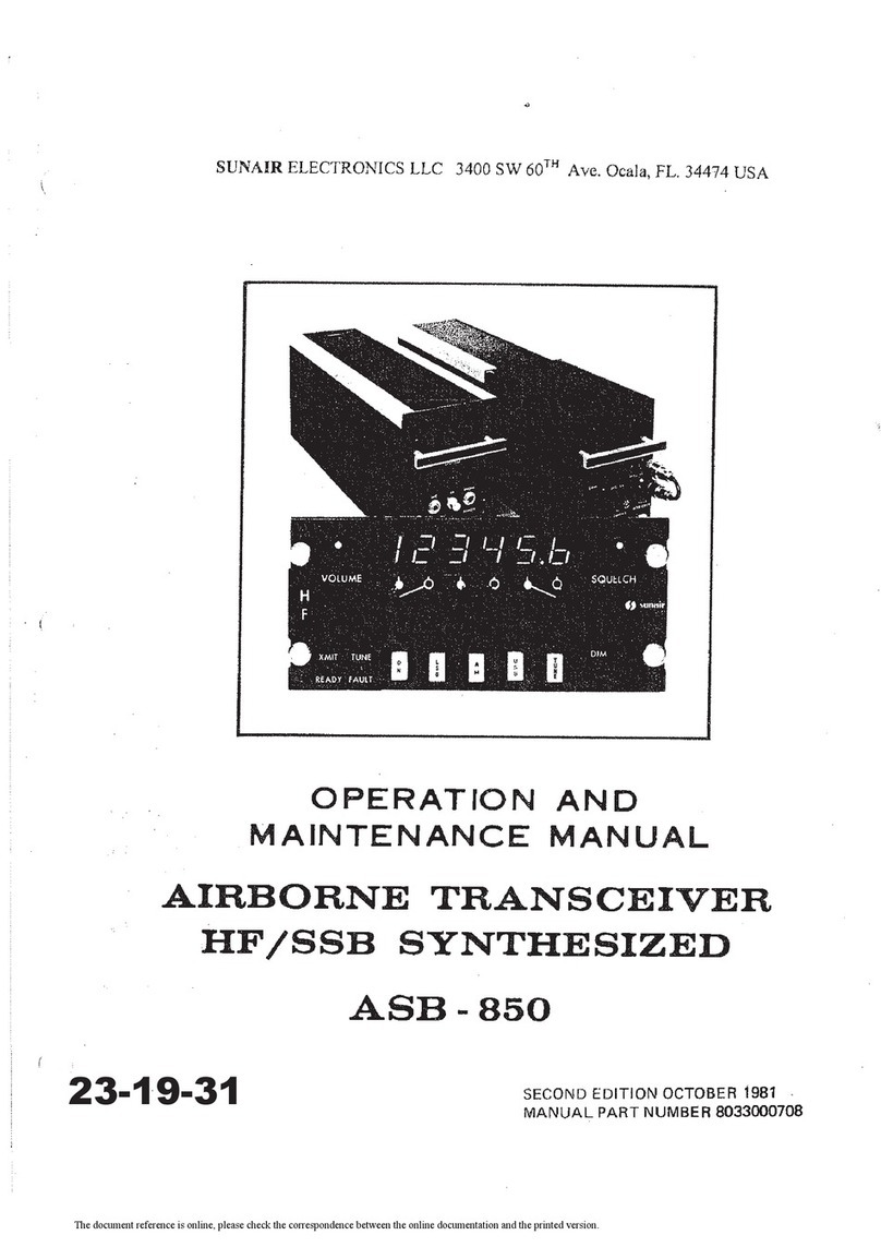
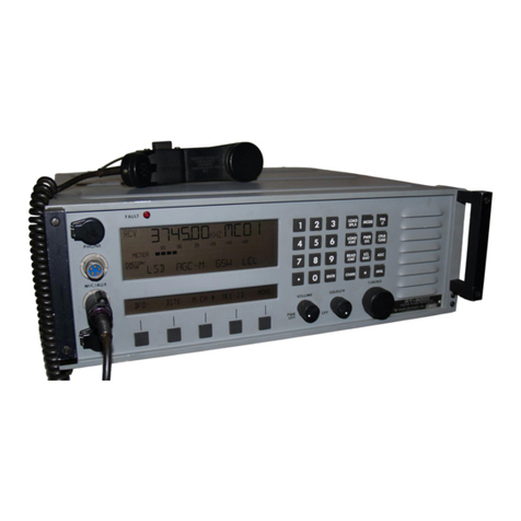
sunair ASB-500 User manual

TM-8040000718
AIRBORNE TRANSCEIVER
HF/SSB SYNTHESIZED
SYSTEM
ASS-500
~
INSTALLATION and OPERATION
MANUAL
SUNAIR
3101
SW
Third Avenue,
Ft.
Lauderdale,
FL
33315-3389

ASS-500
INS
LLATION
AND OPERATION
MANUAL
FOURTH EDITION, JULY 1995
ACU-150D SUPPLEMENT INCLUDED
MANUAL PART NUMBER 8040000718

1.1
SCOPE
SECTION I
GENERAL INFORMATION
SUNAIR .0.58-500
The manual contains the necessary information to install and operate the ASB-500 Transceiver, and includes
additional information required to test the Transceiver.
1.2 TRANSCEIVER DESCRIPTION
11.2.1
GENERAL I
The ASB-500 is a high quality single sideband Transceiver covering the frequency range of 2.0000 to 17.9995
MHz. Modes of operation are Upper Sideband (USB), Lower Sideband (LSB Optional), and amplitude Modula-
tion (AME). The Transceiver is fully solid state and frequency is synthesized
in
500 Hz steps. The unit
is
designed to meet FCC requirements for Part 87, and FAA TSO
C31
c and C32d.
The ASB-500 is composed oftwo major assemblies: the Receiver/Transmitter (RT-510) and the Remote Con-
trol Head (SCU-55).
11.2.2
RECEIVERrrRANSMITTER
-1AI
The Receiver/Transmitter contains the frequency synthesizer as well as all receive and transmit circuitry. The
synthesizer provides the local oscillator frequencies (selected from the Remote Control Head) in 500
Hz
steps.
All
frequencies are derived from an ovenized crystal oscillator which provides frequency stability of 1x10"Hz
over the full specified ambient temperature range of the radio after a two minute warm-up.
The Receiver/Exciter circuits employ high quality crystal filters both
in
the front end of the radio and in the IF
section for sideband selection. The first IF
is
33.6 MHz, well above the
18
MHz upper limit ofthe Transceiver,
providing
an
unusually high spurious signal rejection found only
in
this modern frequency scheme.
Bandpass filtering is included
in
the Receiver/Exciter circuitry to remove harmonics and spurious from the
Exciter, and eliminate out of band interference
in
the Receiver. Additional low pass filtering is provided at the
output of the power amplifier for harmonic rejection.
Multiple voltage regulation is used to provide superior power supply transient suppression. The aircraft supply
is
first filtered, then regulated to 18 VDC (used bythe oven standard), and finally regulated to 12 VDC for use by
the Transceiver low level Circuitry. The 12 VDC is further regulated
on
the synthesizer board to 5 VDC for use
by the digital circuits.
11.2.3 REMOTE CONTROL -
2A
I
The remote control head contains the switches which supply digital frequency information to the synthesizer
in
the Receiver/Transmitter unit, and to the LED display drivers. Also included are the VOLUME and SQUELCH
controls,
an
auxiliary DIMMER control, coupler status lights, and a push-button MODE switch.
Both printed boards used
in
the control head are plug-in for easy removal and servicing.
1-1

SUNAIR
ASS-SO~
1.3 TECHNICAL SPECIFICATIONS
TEMPERATURE: Electrical and physical specifications of the Sunair ASB-500 Transceiver are listed below.
11.3.1 GENERALI
APPROVALS: US FCC type accepted to part 87. US FAA authorized to TSO C31c and C32c.
FREQUENCY RANGE: 2.0 to 17.9995 MHz (500 Hz steps).
NUMBER OF CHANNELS: 32,000 synthesized.
FREQUENCY RESOLUTION: 500 Hz steps. Digital LED readout.
FREQUENCY STABILITY:
±20
Hz maximum overrated temperature range.
OPERATING MODES: USB, AME, (LSB Optional).
DUTY CYCLE: Voice, continuous.
ENVIRONMENTAL CATEGORY: BAAAAX, TSO C31a and C32c.
ALTITUDE: 30,000
Ft.
TEMPERATURE: Non-operating: -50' to +
71
'C.
Short term operating: +71'C.
Operating: -46"C to +55'C. (TSO Cat.
B)
VIBRATION: 10 to 500 Hz, 5g peak -(TSO Cat.
A)
(control head: 10 to 500 Hz, 1.5g max.; 0.25g from 55 to
500 Hz -TSO Cat. C)
HUMIDITY: 95% at +50'C.
SHOCK: 15g peak,
11
ms duration.
POWER INPUT: 27.5 VDC +10%, -20%, at 2.7A Receive 13A peak Transmit.
DIMENSIONS:
Transceiver -1/2 ATR long case. 4.875W x 7.625H x 15.5L (inches). 12.38W x 19.37H x 39.37L (cm).
Add 1.625"H (4.13H
cm)
for shockmount.
Control Head: 5.75W x 2.625H x 5.0D(inches).
14.61W x 6.67H x 12.700 (cm).
WEIGHT: Transceiver 16.0 Ibs (7.2Kg.) 17.5 lb. (7.9Kg.) with shockmount.
Control head: 1.8 Ibs (0.8 kg).
1-2

11.3.2 RECEIVER I
SENSITIVITY:
SSB -0.5 uV max. into 50 Ohms for 10dB S+N/N.
AM -3.0 uV max. into 50 Ohms for 10dB S+N/N.
SELECTIVITY:
SSB -
350Hz
max. to 2500 Hz min. at -6 dB.
6.0 kHz max. at -60 dB.
AM
-5.0 kHz min. at -6 dB.
20 kHz max. at -60 dB. ,
AUDIO OUTPUT: 50 mW into 600 Ohms and 150 Ohms, unbalanced.
AUDIO DISTORTION: Less than 10% at 50
mW.
GAIN: 10 uV nominal for 50 mW audio output.
IF REJECTION: Not less than -70 dB.
IMAGE REJECTION: Not less than -80 dB.
AGC: Fast attack, slow release.
Threshold: 5 uV nominal.
10 dB max audio change for 94 dB RF input change.
SUiIIAIR
ASS-sao
INTERNAL SPURIOUS RESPONSE: 99.5% below equivalent 0.2 uV noise input at antenna terminals.
EXTERNAL SPURIOUS RESPONSE: -65 dB below 10 dB S+NIN reference.
11.3.3 TRANSMITTERI
POWER OUTPUT:
SSB -100 Watts PEP
±1
dB.
AM -35 Watts carrier, nominal.
HARMONIC & SPURIOUS SUPPRESSION: -40 dB.
CARRIER SUPPRESSION: -40 dB.
UNDESIRED SIDEBAND SUPPRESSION: -50 dB at 1.5 kHz.
INTERMODULATION DISTORTION: -29 dB below 2 tone PEP output.
HUM AND NOISE LEVEL: -40 dB.
1-3

SUNAIR ASB-500
1.4 EQUIPMENT SUPPLIED
The following table is a list of equipment, with their appropriate Sunair part numbers, supplied with the ASB-
500 Transceiver. Sunair Part No.
1.4.1
Receiver(Transmitter,
RT-51
0
1.4.2 Remote Control Head, SCU-55
1.4.3 Operation and Maintenance Manual
1.4.4 Installation Kit, consisting of:
Shockrack with isolators
Connector,
RF,
BNC, UG-88/U
Connector, Power, 2 Pin Round.
Connector, Coupler, 17 Pin Round.
Connector, Control, RT-510 (Power 50 Pin Rect.)
Connector, Control, SCU-55 (Power
61
Pin Round.)
Connector, Audio, SCU-55 (Power 14 Pin Rect.)
Cable Clamp
Cable Clamp
Reducing Adapter
Manual, Installation and Operation
1.5 EQUIPMENT REQUIRED
BUT
NOT SUPPLIED
1.5.1
Antenna Coupler, ACU-150D
1.5.2 Antenna, wire
or
integral airframe.
1.5.3 Microphone, noise cancelling.
1.5.4 600 ohm headphones.
1.5.5 Cable Assembly, Power (specify length) 2 conductor.
1.5.6 Cable Control,
RT-51
0 to SCU-55 (specify length).
INOTE: I
1-4
All cables may be fabricated bythe installer
in
accordance with
Figure
2.
8040000599
8040400091
8040000700
8040001595
8040001790
0744030005
0754530001
0754630005
1003390030
0754510000
0754940004
0754270009
1000200001
1001250028
8040000718
Sunair Part No.
8064201098
0871510006
0840180004
8033008504
8040007500

1.6 OPTIONAL EQUIPMENT· NOT SUPPLIED
1.6.1
Encapsulated Anti·Precipitation Static Wire Antenna
Kit.
1.6.2 Microphone, Noise Cancelling
1.6.3 Spare Soard Kit ASS-500
1.6.4 Spare Parts Kit ASS-500
1.6.5 Ancillary
Kit,
consisting
of:
Extender card
Key,
Hexspline socket
1.6.6 Headphones
1.6.7 Lower Sideband (Factory Installed)
SUNAIR ASS·sao
Sunair Part No.
0951580001
0871510006
8040900093
8040900590
8040001293
8040002591
0882100009
0840180004
8040050804
1-5

SUNAIR
ASS-SOO
1-6
CAUTION
TO INSURE THAT CABLE HAS NOT BEEN DAMAGED DURING SHIPMENT,
ALL CABLE ASSEMBLIES MUST BE CHECKED FOR CONTINUITY
OR
SHORTS, FROM PIN TO PIN, BETWEEN CONNECTORS BEFORE INITIAL
RADIO
OR
SYSTEM POWER
UP.
WARNING
CONNECTORS INSTALLED BY THE CUSTOMER MUST BE WIRED
IN
ACCORDANCE WITH INSTALLATION INSTRUCTIONS PROVIDED
IN
THE
OPERATION AND MAINTENANCE MANUAL. THE CABLE MUST
BE
CON-
TINUITYCHECKED AFTER INSTALLATION AND PRIOR TO RADIO OR SYS-
TEM POWER
UP.

SUNAIR ASB·5OC
SECTION
II
INSTALLATION
2.1
GENERAL
Section
II
contains all necessary instructions for the unpacking, inspection, and if necessary, reshipping
of
damaged equipment or parts. In addition, further information regarding location and mounting considerations,
powerrequirements, antennaand ground system hook-upsandfinal checkoutsafterinstallation is also provided.
2.2 UNPACKING AND INSPECTION
As soon as you have received your unit(s), unpack and inspect all components and accessories. Check the
packing list to
be
sure you have received all items ordered, and that all items necessaryfor operation have been
ordered. INOTE: I Be sure to retain the carton and its associated packing materials
should it
be
necessary to reship damaged equipment.
Do not accept a shipment when there are visible signs
of
damage
to the cartons until a complete inspection is
made.
Ifthere
is a shortage
of
items
or
anyevidence
of
damage, insiston a notation tothat effect on the shipping
papersbeforesigningthereceiptfrom thecarrier. Ifconcealed damageisdiscoveredaftertheshipmenthasbeen
accepted, notify the carrier immediately
in
writing and await his inspection before making any disposition
of
the
shipment. Afull report
ofthe
damageshould also
be
forwardedtoSunair's Product Services Department. Please
be sure to include the following information for prompt service:
a) ORDER NUMBER.
b)
MODEL
AND
SERIAL
NUMBER.
c)
NAME
OF
TRANSPORTATION AGENCY.
d) APPLICABLE DATES.
Upon receipt
of
this information arrangements will
be
made, by Sunair, for repair or replacement.
2,3 RETURN OF EQUIPMENT TO FACTORY
The
shipping carton fortheASB-500 hasbeen designedtoprotecttheequipmentduring shipment.
The
container
and its associated packing materials should
be
used to reship the unit. When necessary to return equipmentto
Sunair for warranty or non-warranty repair, an authorization
number
is required. This number can be obtained
from
our
Product Services Department:
TELEPHONE: (954) 525-1505,
FACSIMILE: (954) 765-1322.
If the original shipping carton is not available, be sure to carefully pack each unit separately, using suitable
cushioning material where necessary. Very special attention should be given to providing enough packing
material around connectors and otherprotrusionsfrom the unit. Rigid cardboard should be placed atthe corners
of
the equipment to protect against denting. DO
NOT
USE DUNNAGE (STYROFOAM PEANUTS) FOR
PACKING PROTECTION, they mayallowthe
unitto
shiftwhile being shipped, and, therefore, becomedamaged.
2·1

SUIllAIFI
ASS·500
When returning subassemblies
or
components for repair
or
replacement, be sure to pack each separately, using
suitable cushioning material.
Shipment to be made PREPAID consigned to:
Sunair Electronics, Inc.
Product Services Department
3101
SW
Third Avenue
Fort Lauderdale, Florida 33315·3389
U.S.A.
Plainly mark with indelible ink all mailing documents as follows:
US Goods Returned For Repair
Value For Customs -$(Amount)
Mark ALL SIDES
of
the package:
INOTE: I FRAGILE -ELECTRONIC EQUIPMENT!
Sefore shipping, carefully inspect the package to be sure it is
marked properly and is securely wrapped.
2.4 GENERAL INSTALLATION AND MOUNTING INFORMATION
General instructions for installation and mounting are given for the ASS-500. Satisfactory operation
of
this
equipment will depend upon the care and thoroughness taken during installation.
12.4.1 GENERAL INFORMATIONI
a. The location
of
the Receiver!Transmitter is not critical and may be placed anywhere there is avail-
able space within the fuselage. However, to minimize transmit power loss
in
coaxial cables con-
necting the transceiver to the antenna coupler, it is desirable to mountthe transceiver in the same
general area as the
antenna
coupler.
INOTE: I Installation
of
the Receiver!Transmitter must conform to the
Altitude!Temperature restrictions detailed in the equipment
specifications.
b. Install the Remote Control Head in the cockpit in any convenient location.
c.
The installations should be carefully planned beforehand in accordance with the drawings on
the following pages.
2.5 POWER REQUIREMENTS
The ASS-500
is
designed to operate from a nominal 27.5 VDC +10%, -20%, source. The system should be
connected to the source through the aircraft circuit breaker panel, using a 20 ampere breaker. The Antenna
Coupler receives its power from the Transceiverthrough a 5 amp Sio Sio fuse mounted
on
the Transceiver front
panel. All low level voltages used
in
the Remote Control are current limited to safe levels by voltage regulators
and do not require fusing. Power used
in
the low level stages
of
the Transceiver is current limited, but is also
fused inside the unit by a 5 amp standard fuse to protect against voltage regulator failure.
2-2

SUNAIR
ASS-SOO
2.6 GROUNDING REQUIREMENTS
12.6.1 GENERAL\
Connect the ground straps provided on the mounting rack securely to
the
aircraft frame.
2.7 CABLE FABRICATION
12.7.1 GENERALI
The cables listed in paragraph 1.5 must be wired to their appropriate connectors as shown in Figure 2.8,
Interconnect Wiring Diagram.
.,
All cables are available from Sunair with the exception
of
the audio wiring from Remote Control Head connector
2A3J2. Sincethis wiring must be routed to various locations
in
the aircraft instrumentpanel, the installer should
fabricate this cable using standard aircraft installation practices.
2.7.1.1
If
no main cockpit dimmer exists,
or
control head dimming independent
of
the main cockpit dimmer is
desired, connect a jumper
in
connector 2A3P2 between pins P and
H.
If
this is done, do not connect pin H to the
main cockpit dimmer. Now the full dimming range is available using the control head dimmer only.
12.7.2 CHECKS AFTER FABRICATION I
2.7.2.1 SYNTHESIZER PROGRAMMING
Each cable must be checked for continuity and short circuits to other pins. Wiring between the Control Head
and the Transceiver is pin to pin: "A" to "A",
"8"
to "8", etc.
In
order to be certain the synthesizer is being
programmed correctly, it is necessarythat the output carrierfrequency be checked with a counter. Each decade
frequency must be checked from 0 to 9 to verify that the wiring
of
cable 8040007500
is
correct. See Figure
2.1
for a recommended test set-up to verify operation
on
the bench.
Rotate each frequency switch through all ten positions and check
for
the correct frequency readout on the
counter. The 500 Hz dial alternates between "5" and "0" as the switch is rotated. The 10 MHz switch when
rotated from the fully CCW position will showa blank, then a "1", and finally a "0". The"0" position is superfluous
and shuts down the transceiver. The Remote Control display will flash, denoting an out
of
limit condition.
INOTE: I
2.7.2.2 SAND SWITCHING
Any frequency selected below 2.0000 MHz
or
above 17.9995
MHz
is out
of
limit which will cause
the
frequency
display to
flash and will shutdown the radio. A "0"
in
the 10MHzposition
is also an out
of
limit condition.
8andpass filters are located
on
the first mixer board and low pass filters are located in the Filter Module. These
filters are automatically switched by the 10 MHz and 1 MHz frequency switches in the Control Head.
2-3

SUNAIR
ASS-SOO
Operation ofthese filters may be checked by monitoring the AM carrier output
in
each band. The bands are
divided as follows:
Freq. MHz Band
2-2.9995 1
3-3.9995 2
4-5.9995 3
6-8.9995 4
9-12.9995 5
13-17.9995 6
Connect the equipment as shown
in
Figure 2.2.
Depress the
ON
push button, depress the AM Mode,push button and set the frequency for the middle of each
band. Key microphone and check for approximately 35 watts power output
in
each band. Ifthe bands are not
being switched properly, the power output will be essentially zero on the wattmeter
in
the nonoperating band:
INOTE: I If the band channel drive motor can be heard continuously
rotating
in
the Transceiver, this is generally an indication that
two or more band lines are grounded within the cable or
connectors.
2.7.2.3 MISCELLANEOUS CHECKS
Other functions that must be verified are shown
in
the following chart:
Symptom
1. VOLUME control no audio
2. SQUELCH control no squelch fully CCW
3.
TUNE command coupler doesn't start to tune
4. FAULT indicator no fault light when system
is
first turned
on
5.
TUNE indicator no tune light during coupler tune
6.
READY indicator no green ready light after successful coupler tune
2-4

8 Cable
040007500
"l2.
f
0
0 0 0
Control
Head
SCU-55
Cable
8040007500~
j
0
0 0 0
Control Head
SCU-55
SUNAIR ASS-500
Jl
.....
RT-510
II
50 Ohm
Dummy
High
J2 Load Impedance
RG-58
.-
Counter
J6
TEE
I "
28
VDC "
lOA
Figure
2.1
Test Set-up for Synthesizer Programming.
Jl
RT-510
~
Watt
50 Ohm
~
Meter
Dummy
Load
J6
i
28
VDC
lOA
Figure 2.2 Band Switching Test Set-up.
2-5

SUNAIR
ASS-SOO
2.8 ANTENNA INSTALLATION
12.8.1
GENERALI
The installation of a high frequency antenna
on
an aircraft requires the consideration of two prime factors: the
shape or configuration
of
the antenna must allow the transceiver to transmit and receive efficiently; the appear-
ance of the antenna must be pleasing and the flight characteristics must not drastically alter aircraft perfor-
mance.
However,
in
many cases,
in
an effort to achieve a pleasing appearance, the antenna is located
in
a position
which drastically reduces its efficiency or radiation characteristics. So care must be taken to select
an
antenna
that does not overly favor
anyone
factor to the detriment ofthe others.
12.8.2 FACTORS TO BE CONSIDERED 1
In
order to select the best antenna, consideration must be given to the following factors:
1. Type of aircraft
a.
Size, shape, airspeed
2.
Required communications range
3.
Transmitter frequencies
4.
Antenna flight requirements
5.
Possible antenna coupler locations
6.
Antenna radiation characteristics.
Aircraft size and shape is important as it may restrict the types
of
possible antennas. Aircraft speed must be
considered, as 260 MPH and faster aircraft cannot generally use a wing tip attached V antenna. This type of
aircraft may also operate
in
icing conditions which adversely affect V antennas more than the straight type.
The end user's communications distance requirements must be considered, particularly if long-range, such as
800 miles and greater, is required
on
frequencies as low as 6 to 8 MHz. This requires a V antenna
or
a long
straight antenna 35 feet
or
longer, if ungrounded.
Transmitter frequencies are generally determined by the area of operation and stations to be worked. These
in
turn can affect the antenna selection. If most ofthe frequencies are above 5 MHz it
is
possible to use a shorter
or straight antenna, as coupler efficiency above 5 MHz is good regardless ofthe antenna type.
The antenna aerodynamic requirements are related to the aircraft type and operating capabilities. Generally,
the best aerodynamic design results
in
the poorest radiating antenna when considering only ungrounded anten-
nas, and care must
be
taken here
in
order not to degrade the system operation.
The antenna coupler location dictates the location of one end of the antenna. The output ofthe coupler is the
beginning of the antenna and the antenna wire inside the aircraft must be restricted
in
length, ideally not more
than 6 inches to a maximum of 12 inches, unless coax feed
is
used for the antenna.
The antenna radiation characteristics
(hOW
well does
tt
radiate or receive a signal) is generally the hardest to
determine. It is always best to install an antenna that has proven
to
perform well
in
past installations. The
antennas shown on the following pages have all been installed and used with success
on
various aircraft.
Some will work better on one type of aircraft than another, particularly the grounded type. The grounded an-
tenna to the engine nacelle or vertical stabilizer has worked well on many different aircraft. It may
be
necessary
to try several locations and types of antennas
in
order to satisfy all
of
the factors outlined here and not overly
compromise
anyone
factor.

SUNAIR
ASS-500
Antenna
Tunar
8
to
14 Foot Grounded to Vertical Stabilizer
Ground
or
Ground
Dr
Insulato
29
10
45
Foot
"V"
Grounded
or
Insulated
Ground
30
to
50
Foot
Grounded
or
Insulated
22
to
45
Foot UStraight" Grounded or Ungrounded Antenna
Figure 2.3 Typical Antenna Configurations
2-7

SUNAIR
ASS-SOO
Ground
10
to
20
Foot To Horizontal Stabilizer
/GrOUnd
10
to
20 Foot
To
Wing
Figure 2.3 Typical Antenna Configurations (Cont.).
2-8

SUNAIR ASB-500
Vertical Fin Anchor Kit
5 V-Tension Unit
Feed-thru Insulator
Insulated Antenna
Strain Insulator
7 Wing
TIp
Bracket
Figure
2.4
Antenna
Kit Installation
ANTENNA KIT (ANTI-PRECIP)
PN
0951580001
ITEM DESCRIPTION
1 Feed-thru Insulator
2 60 Feet Insulated Antenna Wire
3 Tension Unit
4 Vertical
Fin
Anchor Kit
5 V-Tension Unit
6 Strain Insulator
7 Wing
TIp
Bracket
8 Wire Retraction
Tool,
Short
9 Installation Instructions
Table
2.1
Antenna
Kit
Components
2-9

SUNAIR
ASS-SO~
Figure 2.5 Antenna Grounding.
12.8.3
ANTENNA KIT INSTALLATION1
I
I
strapOil'riwt
to
skin topSI'1I11!1ty.
Must
ba
SKuro
end vary low
rabrtaRCG
contee!:,
,_
tfuln 1 mill1ohm.
For information to install the Antenna Kit (PN09S1580001) refer to Figure 2.4. Table
2.1
lists the items
in
the
Antenna
Kit.
12.8.4
ANTENNA GROUNDING METHOD 1
For straight grounded antennas (see Figure 2.5), the antenna
(A)
from feed through insulator (Item
1,
Table
2.
1)
is
fed through the V-tension unit (Item
5)
and clamped or tied with nylon cord
(as
shown) to proper length.
Ground antenna with ground lug to Item 4 ofTable
2.1
or aircraft skin. Ground connection MUST be secure, low
resistance and capable of high current.
2-10

SUNAIR
ASS-SOO
.687" DIA.
.199"
DIA'~
-+-+-t--
-$-_
.750"
.750"
I
Mounting Dirnsnsions
.,
A i':ylon
Ba~1!
Plat~
B Anll'llIHI Wife Connector
Bolt
C Anlcllna Wire
o
Washer
E
TCrlnlnal
Lug
F Lock NUl
Figure 2.6 Feed-Thru Insulator
12.8.5 FEED-THRU INSULATORI
For proper installation of the Feed-Thru Insulator (Item 1 ofTable 2.1) refer to Figure
2.
6 and the following text.
Strip back polyethylene shield
(C)
to expose approximately 4" of antenna wire core. Insert core into connector
bolt
(8)
and
extract
from
slot.
Insert
washer
(D)
as
shown.
Wind
wire
around
connector
bolt
(8)
31/2
to 4 turns. Install terminal lug
(E)
of antenna lead and secure with lock nut (F), as shown
in
Figure
2.
6.
12.8.6 V-TENSION UNIT I
Application of an V-Tension Unit (Item 5 of Table 2.1) for a
"V"type
antenna, refers to Figures 2.4 and 2.7.
The Antenna
(A)
is connected to the feed-thru insulator (Item 1), Table 2.1) and routed via the vertical stabilizer
by
the use of the V-tension unit (8), as shown. The end is connected atthe wing tip.
A
Figure 2.7 V-Tension Unit
A Insulated Antenna Wire
B V-Tension Unit
2-11

SUIllAIR
ASS-SOO
2.9
SElCAlOPERATION
Audio for operation of Selcal equipment is available through the transceiver front panel phone jack. This audio
level
is
not controlled by the remote control unit volume control but remains essentially constant.
2-12
Table of contents
Other sunair Transceiver manuals