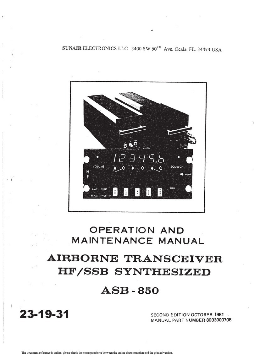
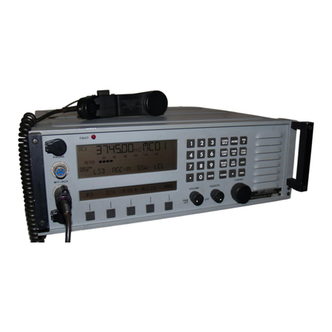
sunair ASB-850 User manual

INSTALLATION AND
OPERATION MANUAL
AIRBORNE TRANSCEIVER
HF/SSB
SYNTHESIZED
ASB
-
850
sunair
electronics,
inc.
.
3101
S.W.
3rd
Avenue.
Fort
Lauderdale.
Florida
33315-3389
7
-Y
Cable:
SUNAI
R
Telex:
51
4443
phone:
(305) 525-1505-
The document reference is online, please check the correspondence between the online documentation and the printed version.

The document reference is online, please check the correspondence between the online documentation and the printed version.

CAUTION
TO
INSURE THAT CABLE HAS NOT BEEN DAMAGED DURING SHIPMENT,
ALL CABLE ASSEMBLIES MUST
BE
CHECKED FOR CONTINUITY
OR
SHORTS,
FROM PIN TO PIN, BETWEEN CONNECTORS BEFORE INITIAL RADlO OR
SYSTEM POWER UP.
WARNING
CONNECTORS INSTALLED
BY
THE CUSTOMER MUST BE WIRED INACCORD-
ANCE WITH fNSTALLATlON tNSTRUCTIONS PROVIDED IN THE OPERATION
AND MAINTENANCE
MANUAL.
THE CABLE MUST BE CONTINUITY CHECKED
AFTER INSTALLATION AND PRIOR TO RADIO OR SYSTEM POWER
UP.
The document reference is online, please check the correspondence between the online documentation and the printed version.

The document reference is online, please check the correspondence between the online documentation and the printed version.

SECTION
2
INSTALLATION
2.7
GENERAL
2.3
RESHIPPING
INFORMAT1ON
Section
2
contains all necessary instntctions for the
unpacking. inspection, and if necessary reshippingof
damaged equipment or parts.
111
addition further
in-
formation regarding location and mounting consid-
erations. power requirements. antenna
and
groi~tid
systeni hook-ups, and filial cheokouts after installa-
tion, are also provided.
2.2
UNPACKING AND INSPECTION
Unpack and inspect all partsand eqiiipment as soon
as
received.
,BE slirc
to
rctai~~fhc skippitrg
cartoti a~rd
its associated pack-
itrg nratcrials shofild
it bc rreccs-
sary to reship danta~edeclltip-
nleltt.
Do
not accept
a
shipment when
there
are
visible
signs or damage to tlie cartons i~ntila complete
inspection
is
made.
it
'there
is
a
shortage
of
itenra
or
any
evidence
of
damage
is
noted, insist
on
a
notation to that effect
on
the shipping papers
be-
fore
signing the receipt from the carrier.
If concealed damage is discovered after a sli~plnent
has been acccptecl. notify the carrier irnmecliately
in writing and await his inspection before ninking
ally disposition of tlie shipment.
A
fttll report of
the damage should also
bc
forwardcd to Sunair.
Incliide the following:
(;I)
Order Nilmbcr
I
h\
Mnrltbl
:111(l
Qri:~l
Nt~nll>+.r
.
-,
...v.....
-.S..
--...a.
h.,.
.B,".,,
(c)
Name of Tr:rnsportatioti Agency
The shipping cartons for the
ASB-850
have been
carefully designed
to
protect
the
transceiver and
accessories during shipmetit. This carton and its
associated packing materials should
be
used to
reship the radio.
If
the
original shipping
carton
is
not available,
be
sure to caref~rllypack
each
ilnit separately, using
s~iituble
cushioning material. Very special attention
should
be
given
to
providing
enough
packing
material around controls. connectors. arid other
protrusions from the radio. Rigid cardboard should
be placed at the corners of
the
equipment to
protect against damage
if
the carton
is
dropped.
When
returning one or more sitbassembties for
repair, please ship
AIR
PARCEL
POST
consigned
to:
SUNAIR ELECTRONICS, INC.
3 101 SW 3rd Aventle
Ft. Lauderdale. Florida 3331
5
U.S.A.
Plainly mark with indelible
ink
all mailing docil-
ments as follows.
U.S.
GOODS
RETURNED
FOR
REPAIR
VALUE FOR
CUSTOMS
-
S
100.00
and
be
sure to mark all all sides of
the
pilckitge
"FRAGILE
-
ELECTRONIC EQUIPMENT"
The document reference is online, please check the correspondence between the online documentation and the printed version.

2.4
GENERAL INSTALLATION AND MOUNT-
ING
INFORMATION
Satisfactory operation
of
this equipment will
depend
upon
the
care
and thoroughness taken
during installation.
2.4.1
GENERAL
INSTALLATION
a. Carefully plan the Amplifier/Coupler antenna
installation to minimize the length of wire between
the coupler output and the antenna itself. This
lead should be kept as short asphysically possible,
6
inches orless
is
optimum. The wire inside the air-
craft is
a
part of the antenna, but will radiate
inside the fuselage, not outside. This energy may
cause
interference with other electronic equipment
in
the vicinity. This interference can often be
reduced by using high voltage coaxial cable such
as
RE8/U,
between the coupler and the antenna
feedthrough.
The
coax must be kept short because
coax
lengths longer than
3
feet
can
cause
large
losses,
particularly
at the antenna resonant and
antiresonant frequencies,
when
VSW
R
exceeds
1
0.
b. The location of the ReceiverIExciter unit is
not critical, and may be placed anywhere there is
available space within the fuselage.
Installation
ol
!he
A
mplifierl
Cuupler and ReceiverlExciter
musf conform
to
the
A
ltitudel
Temperature resrrictions detail-
ed
in the equipmc~rspecifica-
tions.
c. Install
the
Remote Control Head
in
the cockpit
in any convenient location.
d. The installations should be carefully planned
beforehand in accordance with the drawings on the
following pages.
2.5
POWER
REQUl
REMENTS
The
ASB-850
is designed to operate from
a
nominal
27.5
VDC
+
10%,
-
20%,
source.
The
sys-
tem should be connected to the source through
the
aircraft circuit breaker panel. using
a
20
ampere
breaker. The Receiver/Exciter receives aircraft
28V
through a
5A
SB fuse mounted in the PAICpIr.
All low level voltages
used
in
the
Remote Control
are cilrrent limited to safe levels
by
voltage regula-
tors and do not require fusing. Power used in the
PA/Cplr is fed through a
10A
S0
fuse located in
the PAICplr.
2.6
GROUNDING
REQUl
REMENTS
2.6.1
GENERAL
It
is
very important that all ground straps provided
on the mounting racks and
the
ground strap attach-
ed to the rear panel of the PAICplr be securely con-
nected to the aircraft frame.The radiation resistance
of
some aircraft antennas is q~~itelow, sometimes
less than
1
ohm
at
the lower frequencies. In order
not
to
decrease the efficiency the bonding straps
from
the PA/Cplr must be very securely bonded
to the aircraft such that the resistance readings
should
be
in the order of
1
milliohm or less from
the aircraft frame to the ground portion of the
antenna RF output connector.
3A
156. Connecting
all ground straps properly should resi~ltin
an
ade:
quate ground system.
2.7
CABLE
FABRICATION
2.7.1
GENERAL
The cables listed in paragraph
1.5
must be wired go
their
appropriate connections as shown
in
Figure
2.8
Interconnect Wiring Diagram.
Cable
Fabrication
is
shown in Figure
2.9.
All
cables are available from Sunair
with
the
excep-
tion of
the
audio wiring from the control head con-
nector
2A3J2.
Since this wiring must be routed to
various locations in the aircraft instrument panel
the installer should fabricate this cable
using
stsn-
dard aircraft installation practices
The document reference is online, please check the correspondence between the online documentation and the printed version.

2.7.2
CHECKS
AFTER
FABRICATION
2.7.3.1 SYNTHESIZER
PROGRAMMING
Each cable must be checked for continuity and
shorts to other pins. All wiring is pin to pin;
"A"
to "A", "B" to
"B"
etc. In order to be certain
the synthesizer is being programmed correctly it
is necessary that the exciter frequency be checked
with a counter as each decade frequency must be
checked from
0
to
9
to verify that the wiring of
cable 8040007500 is correct. See Figure
2.1
for a
recommended test set-up to verify operation on
the bench.
Rotate each frequency switch through all 10
positions and check for the correct frequency
readout on the counter.
2.7.2.2
BAND SWITCHING
Bandpass filters are located in the exciter unit
at the exciter output and low pass filters are
located in the PA/Cplr unit at the output of the
power amplifier. These filters are automatically
switched by the 10 MHz and
1
MHz
frequency
switches in the control head.
Operation of these filters may be checked
by
monitoring the power output of the PA in each
band.
Bands are divided as shown below:
Freq.
MHz
Band
Connect the equipment as shown
in
Figure
2.2.
Turn equipment
ON
and set mode switch to AM
and set frequency for the middle of each band.
Key microphone and check for power output in
each band. If the bands are not being switched
properly the power will be essentially zero
on
the
watt meter in the non-operating band. Note:
The
PA
filters are of the low
pass
type
so
a
low
band
frequency could pass through
a
higher band but
not the reverse.
2.7.2.3
MISCELLANEOUS CHECKS
Other functions that must be verified are shown
in chart form below. Functions such as audio,
squelch,etc are self explanatory and are not shown.
Symptonsof Incorrect
Wiring
I
-
VHF
VC0
Steer Sluggish frequency lock or
failure to lock.
2
-
L0
Digit Steer Same
as
I.
3
-
Tune Command Failure
of
Coupler
to
start
tuning.
4
-
Fault Indication No fault light when sys-
tem first tuned on.
5
-
Tune lndication No tune light and no fault
light aftercoupler has suc-
cessfully tuned antenna.
6
-
ACC
AM
power output exces-
sively high, over 50 watts.
7
-
ALC
(V)
No
SSB
power control,
signal
flat
tapping and ex-
cessive power reading on
wattmeter when talking
into microphone (over
50
watts).
2.8
ANTENNA INSTALLATION
2.8.1
GENERAL
The installation of a high frequency antenna on an
aircraft involves the consideration of several factors.
The shape or configuration of the antenna must
allow the transceiver to transmit and receive as
required by the user. The user or aircraft owner
also i~si~allyhas a requirement regarding appearance
and flight qualities of the antenna and of course
these should be considered by the installer also.
However, as occurs in most things in nature,
The document reference is online, please check the correspondence between the online documentation and the printed version.

Figure
2.1
Test Set-up
To
Check
Synthesizer
Programming
PAlCPLR ReclExc
RF
Figure
2.2
Band
Switching
Test
Set-up
5.
RG-58
3
No Connection
28V
P.S.
.
RI
F
p~
53
Watt
JZ
J1
c>
I
PAICPLR
J1
J4
52
Meter
5A
J2
>
2
to
30
MHz
Control
Head
52
REC/EXC
J1
R
F
%-
TO
CHECK
COUPLER TUNING REMOVE
50
OHM LOAD
AND
WATT
METER,USE SIMULATED ANTENNA
10
I00
1
EX]
1
::.p.s.
I
q
10
OHM
RESISTORS
IN
100
WA~TS
PARALLEL
m
(SUNAIR
PART
NO.
0160970008
1
50
pf
SUNAIR PART
NO.
17.~~
029020008
-
-
High
lmpedence
J
1
.
Counter
-
If
low impedance counter
0
@@@
used
(Son)
it
may
be
connected directly to exciter
output
if
its
input circult
will
not be
damaged
by
signals
up
to
4V
peak to
peak.
Control
Head
The document reference is online, please check the correspondence between the online documentation and the printed version.
what is best for one parameter
is
not
best for
another. The
HF
antenna is no exception. What
sometimes occurs
is
that the length, shape (con-
figuration) and location of the iIntenna on an air-
craft is something very visible and these factors
receive tlie major consideration. The cornmunica-
tions performance of tile antenna is not readily
apparent or known. partic~~larlyat the time of
installation and decisions are made regarding the
antenna installation which later prove to be bad
for system operation. The solution tlien
is
to
select an antenna that does not overly favor any
factor to the detrement of the other factors.
2.8.2
FACTORS TO
BE
CONSIDERED
In order to select the best antenna, consideration
must
be given to the following factors:
I.
Type of aircraft
a.
Size. shape, airspeed
2.
Required con~rnunioationsrange
3.
Transmitter frequencies
4.
Antenna flight requirements
5.
Possible antenna coupler locations
6.
Antenna radiatiori ckaracteristics.
Aircraft size and shape is important as
it
mily re-
strict the types ot possible antennas. Aircraft
speed must be considered. as
160
MPH
and faster
type of aircraft cannot generally i~sc
a
wing tip
attached
V
antenna. This type
OF
aircraft rnay also
operate in icing conditions which adversely affect
V
antennas more than t11c straight type.
The end users commu~iicationsdist;lncr retluire-
ments must be considered, particularly if long runge
such as
800
rniles and greater is reqttired
on
freq~~enciosas low as
0
to
8
MHz.
This would re-
quire a
V
antenna or
a
long
straight antenna
35
feet
or longer,
if
ungrounded.
Transmitter freqi~encies
arc
getlerully determined
by the area of operation and statiotls to be worked.
These in turn can affect the aritenlla selection. If
most of the freqi~e~iciesare
above
5
MHz
it
is
possible to use
a
shorter or srraiglit atitrn~iaas
coi~plerefficiency above
5
MHz
is good regardless
of the antenna type.
The antenna uerodyt~arnicrerluirrmc.~itsare related
to the aircraft type and operating capabilities.
Generally tlie best aerodyt~aniicdesig~ires~~ltsin
the poorest radiating Jntenna when consiclering
only ungroi~ndedantennas. and care must be
taken here
in
order not to dcgratle the systen?
operation.
The antenna coupler locatioti ~fictatcsthe location
of one end of the atiterinn.
Thc
oi~tp~~tof the
coupler is the beg~nning
ut'
[Izc
antenna and the
antenna wire inside thc aircraft rni~stbe restrict-
ed
in
Iengtli, iclenlly
not
more than
h
inches to a
maximum of 12 inc.hes. i~nlcsscoax teed
is
used
for the antenna.
The antenna radiation cllaractrristics
(tlow
well
does
it
radiate or receive
;I
signal)
IS
gr~ierallythe
hardest to cletermine.
It
is always best
to
install
a11 antenna that has prove!) to pertorm well in
past installatiotls. The atltennas sl~ownoti the fol-
lowing pages Iiave all
brcn
installetl atid used wit11
success on varivi~saircratt. Some w~llwork better
on one type of aircraft than another, particular-
ly
the grounded
type.
The grounded
antenna
to
the
engine nacelle or vertical stabilizer has worked
well
on
many differetlt ;lircraft It m:ly
be
1iect.s-
sary to try several locations nncl
types
ot
antennas
it1
order to satisfy all ot thc. tactors outliner1 Ilere
itnd not overly comproniist. ally o~iefi~ct~r
The document reference is online, please check the correspondence between the online documentation and the printed version.

Ground
(a)
8
to
14
Foot Grounded to Vert~calStab~l~zer
Ground or
Ground
or
Insulate
29
to
45
Foot
"V"
Grounded
or Insulated
or
Insulated
Ground Ground or
(c)
22
to
45
Foot "Stra~ght"Grounded or Ungrounded Antenna
Figure
2.3
Typical
Antenna Configurations
The document reference is online, please check the correspondence between the online documentation and the printed version.
TYPICAL
ANTENNA
C'ONFICURATION
Figure
2.3
Typical Antenna
Configurations
(Cont.)
I
(a)
10
to
20
Foot
To
Hor~zontal
Stabilizer
Ibl
10
to
20
Foot
To
Wing
A
The document reference is online, please check the correspondence between the online documentation and the printed version.

Figure
2.4
Antenna
Kit
Installation
Table
2.1
Antenna
Kit
Components
The document reference is online, please check the correspondence between the online documentation and the printed version.

i
to
skin separately.
Must
be
secure
and
very
low
resistance
contact,
Isso
than
1
milliohm.
Figure
2.5
Antenna
Grounding
2.8.3
ANTENNA
KI'T
INSTALLATION
2.8.4
ANTENNA GROUNDING
METHOD
For information to
install
the Antenna Kit For straight grounded antennas (see figure
2.51,
the
(PN095
158000
1)
refer to Figure 2.4. Table 2.1 lists antenna (A) from feed through itlsulator (Item
1,
the items in the Antenna Kit. Table 2.1) is fed through the insulated tension unit
(Item
3)
and clamped
or
tied with
nylon
cord
(as
shown) to proper length. Ground antenna with
ground lug to ltem
4
of
'Table
2.1
or aircraft skin.
Ground connection
MUST
be secure.
low
resistance
and capable of high current.
The document reference is online, please check the correspondence between the online documentation and the printed version.

6
\
\!
1011
!~J>c
Pla~t!
I!
\II~CIIII~
\V~re
C
onneutor
Bolt
!I~ICIIII;I
IVlre
I)
~L'3~tl~l
i.
T
cr~~l~~~al
Lug
t
L
l.)ck
51.11
.625"
DIA.
189"
DIA.
Mounting
Dimensions
.
b
Figure
2.6
FeedThru
Insulator
2.8.5
FEED-THRU
INSULATOR
2.8.6
INSULATED
TENSION
UNIT
For proper installation of the Feed-Thru Insulator Application of an
insulated
Tension Unit
(PN0713080001,
Item
1
of
Tabie
2.1)
refer
to
(PN07
13220007,
Item
3
of Table 2.1) for a
"V"
Figure
2.6
and the following text. type antenna, refer
to
Figure
2.7.
Strip back polyethylene shield
(C)
to expose
The
Antenna
(A)
is
connected to the feed-thru
approximately
4"
of antenna wire core. lilsert core insulator (Item
I,
Table
2.1)
and routed via the
into connector bolt
(B)
and extract from slot. vertical stabilizer
by
the use of the insulated
Insert washer
(D)
as shown. Wind
wire
around
tension
unit
(B),
as
shown. The end is connected at
connector bolt
(B)
3%
to
4
turns. Install tcrminal
the
wing
tip.
lug
(E)
of antenna lead and secure
with
lock
nut
(F), as shown in
Fig.
2.6.
A
Insul~lcd
,\llrcn~la
\\
trp
U
fnsuluted
Te~~s~on
Unit
Figure
2.7
Insulated
Tension
Unit
2-10
The document reference is online, please check the correspondence between the online documentation and the printed version.

SCU-80
SPARE
A
150
n
AUDIO
OUT
F?
E-
800
CONTROL
HEAD
SPARE
RECEIVER
EXCITER
NOTES:
1.
CABLE
8040007500
SHlELDEDANDJACKETED COMPOSED
OF
4
AWG
no.22
SHIELDED AND.JACKETED WIRES AND
53
MG
no.24
WIRES. OUTER SHIELD_GROUNDEDTO
CONNECTOR
SHELL
ON
BOTH
ENDS.
(SEE
FIGURE
2-14
MICROPHONE OUT
AUDIO GND
GND
CABLE SHIELD
+12V VC0 STEER
MICROPHONE IN
AUDIO GND CONNECT AUDIO TO
GND PIN ~(1504or
PIN
L
CABLE
SHIELD
(600~)AS REQUIRED
+12V VC0 STEER
VC0 STEER RETURN
2.
CABLE
8040007003.
SHIELDED ANDJACKETED COMPOSED
OF
4
AWG
no.22
SHIELDEDANDJACKETED WIRES AND
18
AWG
no.20
WIRES. OUTER SHIELDCONNECTEDTO
CONNECTOR SHELL ON BOTH ENDS. (SEE FIGURE
2-14)
VC0
STEER
RETURN
KEYLINE
SQUELCH CONTROL
RCV AUDIO
POWER ON
+I2V LSB
+IZV AM
+IZV
US6
+I2V DC
TUNE COMMANC
VCLUME CClNTROL
l0
MHt
'0
IC MHZ "I"
10
MHZ '2"
l
MHZ
25"
I MHZ ''22''
I
MHZ
'2''
I
MHZ .'20
BANC
0
VHF VC0 STEER
KEYLINE
SQUELCH CONTROL
boon
AUDIO
OUT
POWER ON
+IZV LSB
+12v
AM
+IZV USB
+IZV DC
TUNE COMMAND
VOLUME CONTROL
10
MHt
'0"
(VHF-VC0 BAND
0)
l0
MH2
"I"
(VHF-VC0 BANO I)
10 MH? "2" IVHF-VC0 BAND 2)
I
MHZ
''23"
I
MHZ"~~"
I
MHZ"~"'
I
MHZ
"20"
SPARE
VHF VC0 STEER
3.
CABLE
0588900001
SHIELDED
no.12
AWG. SHIELD
CONNECTED TO PIN B ON
3AIP2ANDTO AIRFRAME GND
ON THEOTHER END.
4.
GNDWIRE
0594910005
TO BEAS SHORT AS POSSIBLETO
AIRCRAFTGND BUSS.
lAlJl6
a
L
-
-
IAIJ15
PHONE
-??
-
-
TO ANT
S.
TH15 JUMPER CABLESUPPLIED WlTH ACU-810.
SEE NOTE
b
6.
8042390700
HN ADAPTOR USEDFORWIRE ANTENNA
FEED. 3AIP6 USED FOR COAX RG
8
ANTENNA FEED.
3AIJ3
PWR
AMP
son
OUT
i
-
-
7.
CABLES
803300800F.
AND
~8.040007003'
ARECOM-
POSED OFWHITE WIRES WlTH TWO COLOR STRIPES.
ONESTRIPE. CALLEDTHETRACER, ISSMALLER
THAN THEOTHER STRIPE. WHENWIRING THECON-
NECTORS MAKEA CHART SHOWING WHICH COLOR
W1 REISCONNECTEDTOEACHPINANDMAKESURE
THECONNECTOR ONTHEOTHER ENDOFTHECA-
BLE ISWIRED IDENTICALLY. A WHT-BRN-BLU WIRE
IS A WHITE WIRE WlTH A BROWNSTRIPE ANDA
BLUETRACER.
--
-
LOW LIMIT
I
KHZ 'ZO
I
KHt
"2'
FAULT
READY
ICG
HZ'ZO
TUNING
100 HL
'22'.
!GC
HZ 23
LOW DIGIT STEEF
BANC
I
BANC
2
BANC 3
BAND
4
BANG
5
;GO
KHZ"~~"
10
KHZ"20'
I
KHZ ''22
I
KHZ''~~'
100
H£
'2l"
10
KHZ
"23'
100 ~~2'2~'
BANG
6
BAND
7
100 KHE.2'
10
KHL 2'
IG ~~3'2~'
IOC
r.nz
'2*'
g
zu
uo
S
PP
.?
i
5
g2
SPARE
2
ad
SPARE
5'
U
a
SPA
RE
re>
-
SWITCH GNL
LOW LIMIT
I KH2"2°"
I
KHZ
"2'
"
FAULT
READY
loo
~~"20'.
TUNING
100
Hi! .'22',
100
~t-2~-
L0 DIGIT STEER
BAND
l
BAND 2
BANG
3
BAND
4
BAND
5
l00
KHZ -2'"
l0
KHZ
I
KHZ ''22''
I
~~z.23,.
LOO
HZ"Z".
10 KHz '-23-
100
KHZ'~~
''
BAND
6
BAND
7
100 KHZ "2'
''
10 KHZ "2"'
10 KHZ "Z2
''
100 KHZ''22''
2BVDC
28VDC
ALC
(I)
GND
AL: :VSWR)
BAND
5
SPARE
KEYLINE
BANO
7
SPARE
ACC
GND
ALC (V)
GND
CABLE SHlELC
BAND 3
BAND
i
BAND
4
BAND
b
BAND 2
POWER ON
FAULT
TUNE IND
READY
TUNE COMM
TUNE GND
28VDC
28VDC
ALC
(I)
GND
ALC (VSWR)
BAND
5
SPARE
KEYLINE
BAND
7
SPARE
ACC
GND
ALC [V)
GND
CABLE
%IELD
REAR GNO POST
BAND 3 AIRFRAME GND
BAND
I
BAND
4
BAND 6
BAND 2
POWER ON
FAULT
TUNE IND
READY
TUNE COMM
TUNE GXD
IMPORTANT NOTE:
CABLES MUST BE FABRICATEDAS SHOWN INFIGURE 2-14
TO
PROVIDE PROPER RFSHIELDING.
--
p-
--
I
I
--
L---
-1
CABLE SHIELD
CABLE 'ART*
8
80400(!7003
U
aaw
InASSlS
W
wwz
rc
$o~zz
C
=a
z
"OEZEO
0
,_2a3Co
OO~~~a"u~~WWW~
saa~na~o~oa~om
N
a
-
a
m
+ZBVDC,THROUGH
A/
C
2OA
CIRCUIT RRFAKEFI (~3'rE3)
AIRFRAME GND
AIRCRAFT GND
BUSS,#I~AWG
(NOTE
4)
GND B
28v
l
A
ABCDEFHJKLMNPR
~?~~???~?OO~OC
2A3F2
I
I
I
L
1
SHOCK RACK
1
SHOCK
RACK
Figure
2.8
Interconn~ct
Wiring
Diagram
ASB-850
TO
I;RCRAFT'
INSTRUME'NT'PANEL
WIRE SIZE AWG 24
The document reference is online, please check the correspondence between the online documentation and the printed version.

The document reference is online, please check the correspondence between the online documentation and the printed version.

Figure
2.9
Cable
Fabrication
2-12
4
h
!
h
-HEAT
SHRINK
TUBING
EE
NOTE
6
REDUCING
ADAPTER
r
CABLE
CLAMP
UNUSED
CONDUCTOR
Figure
2-9A
NOTES.
1.
Strip outer rubher covering back
from
end of cable as shown.
2.
Pull braid back over outer rubber covering. Pull braid tight to
make
smallest
diameter
of cable.
3.
Slide
(a)
cable clamp and (b)
reducing
adapters over cable as shown.
4.
Put heat shrink tubing over
end
of
Sraied
as
sl~otvn,
5.
Check
tt?
be
sure
caS!e clamp
will
slide
over
heat shrink tulhin~
and
brat:].
Th-
I
vo
:lamps
on
the
cable clamp
should
clamp
aver
:ha
e;cposcd
braid to provide
a
ground
for the
shield.
6,
Any unused conductors should
be
tied together with a small busswire and soldered to outer
braid at one point. Make
sure
cable
clamp will pass over braid.
7.
Caution:
If
8033007508 or
8033008008
are used care should be exercised
to
avoid use of
excess heat on the braid to
prevent
melting the inner conductor insulation. (Conductor
insulation is
PVC).
8.
Strip
1/81?
of insulation off conductors to be soldered in connector.
g,
Solder wires into connector.
10.
Screw adapter into connector. Slide cable clamps up cable and tighten clamps on exposed
braid.
11.
If
Sunair Part No's 8033007508
and
80330080008 are not used, be sure
to
check
O.D.
of
cable to be used to be sure
it
will
fit through
I.
D,
of
cable clamp.
12.
Completed
cable should
look
like Figure
2-9B.
ASSEMBLE
PARTS
PREVIOUSLY
SFOWN
ABOVE,
MAKING
CERTAIN
THAT
THE
CLAMP
IS
MAKING
GOOD
CONTACT
WITH
THE
BRAID.
CLAMP
ON
BARE
BRAID
Figure
2-96
The document reference is online, please check the correspondence between the online documentation and the printed version.

4
1.09
MAX
c'
G
.69
MAX
8,
WEIGHT
22
LBS.
S
19.56
MAX
I
.38
MAX
-
+
.005
Figure
2.1
0 AmplifierICoupler Outline DimensionsACU-810
2-13
The document reference is online, please check the correspondence between the online documentation and the printed version.

RESERVE SPACE FOR
3.0
-1
/-
CONNECTORS AND CABLING
WEIGHT: PA/CPLR.
22.0
LBS.
SHOCK RACK.
1.6
LBS.
2
1.67 MAX
1.375 TYP.
.+l
r.265/.275
DIA.
NOTE:
.20
1
DiA
?'YP
1. A HEIGHT REDUCTION OF 1.4 INCHES MAYB BE OBTAINED
BY
USING THE ALL ATTITUDE SHOCK ISOLATOR KIT.
SUNAIR PART NO. 8033003804
1.8.1 TYP 1.3%
T'r?
TY PICA1MOUNTING
PATTERN
166
DIA-TYP.
OPTIONAL LOW PROFILE MOUNT MOUNTING CUTOUT
23-49
-34-
3
-
Figure
2.1
1
ArnplifierlCoupler Installation Dimensions. ACU-810
2-15
The document reference is online, please check the correspondence between the online documentation and the printed version.

U
1.09
MAX
REF
4
.38
MAX
18.57
MIIX
23-49-3i-
4-
Figure
2.12
ReceiverfExciter Outline Dimensions
RE800)
2-17
The document reference is online, please check the correspondence between the online documentation and the printed version.
Other manuals for ASB-850
1
Table of contents
Other sunair Transceiver manuals