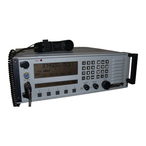
sunair ASB-850 User manual

The document reference is online, please check the correspondence between the online documentation and the printed version.

(
(
(
The document reference is online, please check the correspondence between the online documentation and the printed version.

PRODUCT
SERVICE:
ln
case
of
difficulty
please
contact
the
Sunair
Product
Service
Department
between
the
hours
of
8:00
AM
and
5:00
PM
Eastern
Time,
or
write
ta:
Product
Service
Dept.
Sunair
Electronics,
LLC
3400
SW
60th
Ave.
Ocala,
FI.
34474
U.S.A.
Telephone:
(352)
873-4000
Fax:
(352)
854-6238
Email:
TRAINING:
Sunair
offers
training
programs
of
varying
lengths
covering
operation,
service
and
maintenance
of
ail
Sunair
manufactured
equipment.
For
details
please
Contact
Product
Services
Department.
The document reference is online, please check the correspondence between the online documentation and the printed version.

(
(
/
\
The document reference is online, please check the correspondence between the online documentation and the printed version.

SUNAIR
ASB-850
TABLE
OF
CONTENTS
Section Page
GENERAL INFORMATION
1.
1 Scope . . . . . . .
1-1
1.
2 Trans.r.eiver Description
1-1
1.3 Technical Specifications
1-3
1.4 Equipment Supplied
1-5
1.5 Equipment Required
but
Not Supp!ied . . .
1-5
1.6 Optional Equipment -Not
Supplied . . . . . .
1-6
II
INSTALLATION
2.1
General . . . . . . .
2.
2 Unpacking and Inspection
2.3 Reshipping Information .
2.4 General Installation and
Mounting Information .
2.5 Power Requirements . .
2.6 Grounding Requirements.
2.
7 Cable Fabrication
2.8 Antenna Installation
2-1
2-1
2-1
2-2
2-2
2-2
2-2
2-3
III OPERATION
3.1 System Controls and
Connectors.
3-1
3.2 Checks After Installation 3-4
IV THEORY
OF
OPERATION
i
4.1
General . . . .
4-1
4.2 Synthesizer (1A4)
4-1
4.
2.1
General
4-1
4.2.2 Spectrum Generator
(1A4Al)4-l
4.
2.3 Low Digit Generator
(1
A4A2) . . . . . 4-2
4.
2.4 Translator
(1
A4A3) . . 4-6
4.2.5 V.H.F. Divider
(1
A4A4)
4-7
4.2.6 V.C.O. (1A4A5)
4-9
4.2.7 Synthesizer Mother Board
(1A4A6) . . . . . . 4-11
4.2.8 Temperature Compensated
Crystal Oscillator . . .
4-11
Section
Page
4.3 Receiver . . . . . . . . . .
4.3. l General . . . . . . . .
4.3.2 VHF Mixer Board
(1A3Al)
4.3.3 IF/Fi!ter Board
(IA3A2)
4-11
4-12
4-12
4-13
4-15
4-16
4-16
4.4
4.5
4.6
4.7
4.8
4.3.4 Audio Board (1 A3A4)
Exciter . . . . . . . . .
4.4.1 General . . . . .
.·
.
4.4.2 Sideband Generator Board
(1A3A3)"
. . . . . 4-17
4.4.3 IF/Fi!ter Board
(IA3A2)
. 4-18
4.4.4 VHF Mixer(! A3AI ,Transmit) 4-18
4.4.5 Compressor Board
(1
AS) 4-19
Switching Regulator
(1
A6) 4-20
4.5.1 General . . . . . . 4-20
4.5.2 Switching Regulator . 4-20
4.5.3 5 Volt
OC
Regulator . 4-20
Filter Assembly
(IA2)
4-20
Control Head (2A) . . . . 4-20
Amplifier/Coupler Unit (ACU-810) 4-21
4.8.1 General . . . . . .
4-21
4.8.2 Power Amplifier (3A6)
4-21
4.8.3 Filter Module (3A7) 4-22
4.8.4 Antenna Coupler . . 4-22
4.8.4.1 General . . 4-22
4.8.4.2 Pad, Phase and
Amplitude
Detectors(3A1Al)4-23
4.8.4.3 Control Logic(3A2) 4-24
4.8.4.4 Phase & Amplitude
Control (3A3) . 4-30
4.8.4.5
C3
and C6 Control
(3A4) . . . . 4-38
4.8.4.6 Servo Motor Con-
trol (3A5) . . 4-42
4.8.4.7 Regulator-Detector
(3A8A2) . . . 4-43
4.8.4.8 CI Assembly(3A9) 4-43
4.8.4.9 L4Assembly(3A10) 4-44
4.8.4.10
C3
& C6 Antenna
Modification
Capacitors(3A11) 4-44
4.8.4.11 Typical Tuning
Sequence . . . 4-44
The document reference is online, please check the correspondence between the online documentation and the printed version.

SUNAIR
ASB-850
TABLE
OF
CONTENTS (
Section Page Section Page
V MAINTENANCE AND REPAIR
5.1
General
5-1
5.6.2
IF/Filter
Board (1A3A2) 5-30
5.2 Preventive Maintenance
5-1
5.6.3 Sideband Generator Board
5.3 Cover Removal
5-1
(lA3A3)
5-3 l
5.3. l Receiver/Exciter Assembly
5-1
5.6.4 Audio Board
(1
A3A4) 5-3 1
5.3.2 Remote Control
Unit.
5-1
5.6.5 Compressor Board
(1
AS) 5-31
5.3.3 Amplifier/Coupler Unit .
5-1
5.7 Remote Control (2A) 5-32
5.4 Performance Test
5-1
5.
7.1
Fault Analysis 5-32
5.4.1 Test Equipment .
5-1
5.8 Power Amplifier/Coupler
(3A).
5-33
5.4.2 Materials Required.
5-1
5.8. l Fault Analysis 5-33
5.4.3 Preliminary Preparations 5-2 5.8.2 Primary Voltages 5-37
5.4.4 Receiver/Exciter Test 5.8.3 Grounding Test
Thal
Can
Procedures 5-4
Be
Performed 5-40
5.5 Synthesizer . 5-7 5.8.4
PC
Board Replacement 5-45
5.5.l
Fault Analysis 5-7 5.8.5
RF
Power Amplifier
5.5.2 Subassembly Testing and Servicing . 5-50
Alignment 5-13 5.8.6 Periodic Maintenance. 5-5(
5.6 Receiver/Exciter Board Alignment 5-30 5.8.7 Removal
of
Subassemblies . 5-5"
5.6. l V.H.F. Mixer Board
(1A3Al)
. 5-30 5.9 Schematic Diagrams 5-53
LIST
OF
TABLES
Table Page Table Page
2.l
Antenna Kit Components
2-8
5.6 1 Khz Switch .
5-1
1
4.l Control Logic (3A2) Diode 5.7 1
OO
hz
Switch
5-1
2
Functions 4-28,29 5.8 Course Steering Voltage Readings 5-l2
4.2 Phase and Amplitude Control (3A3) 5.9 Display Segment Illumination
vs.
Diode
Functions
. 4-35,36 Driver
Input/Output.
5-3
2
4-3 7,38
4.3
C-3
and C6 Control (3A4) Diode 5.10 Fault Isolation Table . 5-33
Functions 4-41,42 5
.11
3XA1Al
Connector Voltages 5-38
5
.1
Remote Control Test Positions 5-2 5.12 3XA8A2 Connector Voltages 5-39
5.2
10
Mhz Switch 5-9 5.13 3XA4 Connector Voltages . 5-41
5.3 1 Mhz Switch 5-9 5.14 3Xa2 Connector Voltages . 5-42
5.4 1
OO
Khz Switch 5-10 5.15 3XA3 Connector Voltages . 5-43
5.5 10 Khz Switch 5-10 5.16 3XA5 Connector Voltages . 5-44
(
\
ii
The document reference is online, please check the correspondence between the online documentation and the printed version.

1 SUNAIR
ASB-850
1
LIST
OF
ILLUSTRATIONS
Figure Page Figure Page
2.1 Test Set-up
to
Check
Synthesizer
Programming 2-4
5.12
Receiver/Exciter
Main
Frame
" " Band Switching
Test
Set-up 2-4
Schematic
5-65
2.3 Typical
Antenna
Configurations
2-6,7 5.13
Spectrum
Genera
tor
Schematic
2.4
Antenna
Kit
Installation
2-8
(IA4Al)
.
5-68,69
2.5
Antenna
Grounding
. 2-9
5.14
Low Digit
Generator
(1A4A2)
5-7 l
2.6
Feed~Thru
lnsulator\
. 2-10 5.15
Translator
Schematic
(lA4A3)
. 5-75
2.7 Insulated
Tension
Unit
2-10
5.16
V.H.F.
Divider
(l
A4A4)
5-79
2.8
Interconnect
Wiring Diagram 5.17 V.C.O. Assembly
(l
A4A5)
5-8 I
ASB-850 .
2-1
1
5.18
Synthesizer
Mother
Board
(1A4A6)
5-83
2.9 Cable
Fabrication
2-1
2
5.19
VHF
Mixer
Schematic
(!A3Al)
5-85
2.10
AMP/Coup
Outline
5.20
IF
/Fil
ter
Schematic
(!
A3A2)
5-87
Dimensions, ACU-810 .
..
2-13 5.21 Audio Board
(1A3A4)
5-89
2.l
l AMP
/Coup
Installation
5.22
Sideband
Generator
(1
A3A3)
5-9 l
Dimensions, ACU-81 0 . 2-15
5.23
Receiver/Exciter
Mother
Board
2.12
Receiver/Exciter
Outline
(1A3A5)
. 5-93
Dimensions,
RE-800
2-17
5.24
Compressor
Board
(
lA5)
5-95
2.13
Receiver/Exciter
Installation
5.25 Switching Regu!ator (1
A6)
5-97
Dimensions,
RE-800
2-1
9
5.26
Filter
Module
(!A2)
Intercon-
2. 14
Control
Head
Outline
nection
Diagram 5-99
Dimensions, SCU-80 2-21
5.27
Odd
Channel
Fil
ter
Board
(!
A2A1)
5-l
01
3. J
Remote
Contrai
Head
Front
Panel. 3-3
5.28
Even
Channel
Filter
Board
(1A2A2)
5-J 03
4.J
Receiver/Exciter
Black
Diagram. 4-3
5.29
Contra!
Head
(2A)
Wiring
4.2
CA3053
Schematic
of
Ul
and U2 .
4-14
Diagram 5-J 05
4.3 C3 and C6
Antenna
5.30
Decoder
(2A
l)
Display
(2A2)
Modification
Capacitors
4-45 Boards . 5-J 07
4.4
C3
and
C6
Antenna
Modification 5.31
Power/
Amplifier
Coupler
Capacitors
(Rev. H
or
higher) 4-46
Interconnection
Diagram 5-109
5. l Caver Removal
for
5.32
Pact, Phase
and
Amplitude
ASB-850
Units
5-3
Detectors
(3AlAl)
. 5-111
5.2
Power
Amplifier
Test
Set-up
5.33
Control
Logic
(3A2)
. 5-113
Schematic
5-50
5.34
Phase
and
Amplitude
Contrai
(3A3)
5-1
l5
5.3
Receiver/Exciter
Front
Panel 5-5 5 5.35 C3
and
C6
Contrai
Assembly
(3A4)
5-1
J7
5.4
Receiver/Exciter
Top
View
5-5
6
5.36
Servo
Motor
Contrai
Assembly
5.5
Receiver/Exciter
Bottom
View
5-5
7
(3A5)
5-l
19
5.6
Remote
Contrai
Rear
Panel
5-5
8 5.37
RF
Power
Amplifier
Schematic
5.7
Remote
Contra!
Top
View 5-59
(lA7Al)
.
5-1
21
5.8
Remote
Contra!
Bottom
View
5-60
5.38
Fil
ter
Module
Assembly
(3A
7) 5-l
23
5.9 Power
Amplifier/Coupler
5.39
Regu]ator
Detector
Assembly
Front
Panel . 5-6 J
(3A8A2)
. 5-l
25
5.
IO
Power Amplifier
Antenna
Coupler
5.40
Cl
Assembly
(3A9)
5-127
Chassis Right Side 5-62
5.4
J L4 Assembly
(3Al0).
5-l 28
5. l l
Power
Amplifier
Antenna
Coupler
5.42
C3 and C6 Assembly . 5-129
Chassis
Left
Side . 5-63
5.43
Filter
Module Assembly (3A7) 5-130
iii
The document reference is online, please check the correspondence between the online documentation and the printed version.

(
1
THIS
PAGE
INTENTIONALL
Y
LEFT
BL.ANK.
1 (
(
The document reference is online, please check the correspondence between the online documentation and the printed version.

SUNAIR
ASB-850
SECTION
l
GENERAL
INFORMATION
1.1
SCOPE
The
installation
manual
contains
the
necessary
information.
to
install
and
operate
the
ASB-850
Airbome
Transceiver.
The
maintenance
manual
contains
additional
information
necessary
to
test
and
repair
the
transceiver.
1.2
TRANSCEIVER
DESCRIPTION
1.2. l
GENERAL
The
ASB-850
is
a high
quality
single
sideband
trans-
ceiver
covering
the
frequency
range
of
2.0000
to
29.9999
MHz. Modes
of
operation
are
Upper
Side-
band
(USB),
Lower
Sideband
(LSB),
and
Ampli-
tude
Modulation
(AME).
The
transceiver
is
fully
solid
state
and
frequency
is
synthesized
in l
OO
Hz
steps.
The
unit
is
designed
to
meet
FCC
require-
ments
for
Part
87,
and
FAA
TSO
C3lc
and
C32c.
The
ASB-850
is
composed
of
three
major
assemb-
lies,
the
Receiver/Exciter
(RE-800),
the
Remote
Contra!
Head
ISCU-80),
and
the
Amplifier/Coup-
ler
(ACU-8
l
OJ.
l.2.2
RECEIVER/EXC!TER
-
!A
The
receiver/exciter
contains
the
synthesizer
and
ail
low
level
transmit
and
receive
circuitry.
The
synthesizer
provides
the local
oscillation
frequency
(selected
fram
the
Remo
te
Contrai
Head)
in l
OO
Hz
steps. Ail
frequencies
are
derived
from
a
Temper-
atur
Compensated
Crystal
Oscillator
!TCXO)
which
pravides
instant
on
frequency
operation
with
no
warm
up.
The
frequency
stability
is
better
than
:!:
0.6
X l o-6 Hz
over
the
full
specified
ambient
temperature
range
of
the
radio.
The
long
term
stability
is
:!:
5 X l o-7
per
year,
permitting
long
intervals
between
calibration.
The
receiver/exciter
circuits
employ
high
quality
crystal
filters
bath
in
the
front
end
of
the
radio
and
in
the
IF
section
for
sideband
selection.
The
first
I.F.
is well
above
the
30
MHz
upper
limit
of
the
transceiver,
praviding
the
unusually
high
spuri-
ous
sign.al
rejection
found
only
in
this
frequency
scheme.
A
bandpass
filter
module
is
included
in
the
receiv-
er/exciter
unit
to
remove
harmonies
from
the
exciter
and
eliminate
out
of
band
interference
in
the
receiver.
A plug-in
switching
regulator
assembly,
efficiently
con
verts
t_he
27.5
VDC
aircraft
power
to
+ 12
VDC
and
+ 5
VDC
for
use
by
the
low level
circuitry
and
digital
integrated
circuits.
A
speech
compressor
and
receiver
squelch
are
sup-
plied
on
a plug-in
board.
This
board
may
be
rewired
to
pravide
r.f. gain
contrai
in place
of
squelch,
if
desired.
l.2.3
REMOTE
CONTROL
-2A
The
remote
contrai
head
contains
the
switches
which
supply
digital
frequency
information
to
the
synthesizer
in
the
receiver/exciter
unit,
and
to
the
LED
display
drivers. Also
included
are
the
VOL-
UME
and
SQUELCH
contrais,
an
auxiliary
DIM-
MER
contrai,
coupler
status
lights,
and
a
push-
botton
MODE
switch.
Both
printed
boards
used in the
control
head
are
plug-in
for
easy
removal
and
servicing.
l.2.4
AMPLIFIER/COUPLER
-
3A
This
unit
takes
the Jow level
rf
signal
from
the
receiver/exciter
unit
and
increases
the
power
level
to
1
OO
watts
PEP.
The
amplifier
output
is
rauted
thraugh
a Jow pass filter
module
to
suppress
the
harmonies,
and
then
fed
to
the
automatic
antenna
coupler,
where
it
is
impedance
matched
to
the
an-
tenna.
The
power
amplifier
is
an ail
solid
state
linear
1-1
The document reference is online, please check the correspondence between the online documentation and the printed version.
1 SUNAIR
ASB-850
1
broadband
unit with no frequency
dependent
components.
The
unit is cooled by an integral
heatsink and
is
protected
from damage by internai
Automatic
Level
Control
(ALC) circuits.
The
antenna
coupler
is
connected
to
the
50
ohm
1-2
power
amplifier
output
and
automatically
matches
the
antenna
impedance
to
50
ohms.
The
coupler
is designed
to
tune
the wide variety
of
HF
antennas
that
are installed
on
various aircraft
See para 2.8 for
antenna
types.
(
!
\
The document reference is online, please check the correspondence between the online documentation and the printed version.

1.3
TECHNICAL
SPECIFICATIONS
Elcctrical and physical specilïcations
of
the Sunair
ASB-850 Transceiver arc listed below.
1.3. I GENERAL
APPROVALS
U.S.
FCC type accepted to part 87.
U.S.
FAA authorized to
TSO
C3 Ic and C3 2c.
FREQUENCY RANGE:
2.0
to 29.9999
MHz
( 100
Hz
lncrements).
NUMBER
OF
CHANNELS:
280.000. Synthesized.
FREQUENCY RESOLUTION:
100
Hz.
FREQUENCY STABILITY.
±
:20
Hz
1naximum
over
r:.itcd
temperJture
range.
OPERATING MODES:
USB. LSB. AME.
DUTY CYCLE:
Voice. Continuous.
ENVIRONMENTAL CATEGORY:
BAAAAX, TSO C3 Ic and C32c
ALTITUDE:
30.000 Ft.
TEMPERATURE
Non-opcrating: -
SOOC
to +
71
oc
Short
Term opera
ting::
+ 71
oc
Operating: -460C to + 5
soc.
VIBRATION:
10
to 500 Hz.
5g
peak (TSO Cat.
A).
(Control head:
10
to 500
Hz
1.5G max.
0.:'5 max acceleration IT50 Cat. C).
HUMIDITY
95é{
at
sooc
SHOCK:
6g
peak. 1
lms
duration.
SUNAIR
ASB-850
CRASH SAFETY:
J
5g
peak. 11
ms
duration.
POWER INPUT:
27.5 VDC +
IO~i.
-20'/i. at 2.0 amp receive.
14
amp peak transmit.
DIMENSIONS:
Rcvr/Exctr:
112
ATR long case.
4.875W X 7.62H X
16.8Liinches)
12.38W X
l9.37H
X42.67LtCMl.
Add 1.6" H (4.13 cm) for
shockmount.
Amp/Cplr: 1
/2
ATR long case.
4.875W X 7.625H X 19.SL linches
12.38W X l9.37H X 50.29L
iCM)
Add 1.6" H (4.13 cm) for
shockmount.
Control Head: 5.75W X 2.625H X
5.0Uinches)
14.6W X 6.67H X l 2.7D iCM).
WEIGHT:
Rcvr/Exctr: 16.0 lbs (7.3
kg):
17.6 lbs
(8
kg)
with shockmount.
Ampl/Cplr: 22.0 lbs (
10
kg): 24 lbs (
1O.9
kg)
with
shockmount.
Control Head: 1.8 lbs
iü.8
kg).
1.3.2 RECEIVER
SENSITIVITY: S + N
SSB:0.5 uv max
into
50 ohms
for
10
db
-N-
S+ N
A~::
3.0
uv
max into 50 ohms for
10
db--
N
SELECTIVITY
SSB: 350
Hz
maximum to 2500
Hz.
n1inin1un1
6.0 kHz max at -60db.
AM:
5.0 kHz minimum (a -6db
20
kHz maximum at -60db.
AUDIO OU.TPUT
50 mw into
600
ohms and 150 ohrns.
unbalanced.
AUDIO DISTORTION:
Less
than 1
O'X
at 50 mw.
1-
3
The document reference is online, please check the correspondence between the online documentation and the printed version.

1 SUNAIR
ASB-850
CAJN:
10 uv
nominal
for
50
mw
Audio
Output.
IF
REJECTION:
Not
Jess
than
-70db.
IMAGE
REJECTION:
Not
Jess
than
-80db.
AGC:
Fast
attack.
slow
release.
threshold
5 uv
nomi·
nal: 1Odb
audio
change
for
94db
rf
input
ch:.inge.
INTERNAL
SPURIOUS
RESPONSE:
99.5'.·;
below
equivalent
0.2 uv
noise
input
at
antenna terniinals.
EXTERNAL
SPURIOUS
RESPONSE:
-65db
below
1
Ocib
S + N reference.
N
1.3.3
TRANSMITTER
POWER
OUTPUT
SSB: 1
OO
watts
PEP::': 1
db
AM:
40
watts
carrier.
nominal.
HARMONIC
&
SPUR!OUS
SUPPRESSION
-40db.
CARRIER
SL'PPRESSION
·
40
db.
L'NDESIRED
SIDEBAND
SUPPRESSION:
-
50
db
la
1.5
kHz.
ll\TERMODULATION
DISTORTION:
-29
db
below
2
tone
PEP
output.
llUI
Ac;[)
\OISlc
LlcVEL: -
40
db.
1.3.4
ANTENNA
COUPLER
1-4
RF
POWER
CAPABIL.ITY:
100
watts
average.
VSWR:
1.3: 1
or
better
typical:
1.5: 1
maximum.
TUNING
TIME
3
seconds
typical.
30
seconds
maximum.•
*For
standard
test
conditions
using
the
fol!ow-
ing
test
antenna
impedances:
a) 10 ft.
grounded.
b)
29
ft.
grounded.
c)
8 ft.
grounded
d)
Jetstar.
3)
Mystere
20.
f)
707
tailprobe.
g)
34
ft.
grounded.
For
some
frequency-impedance
combinations
with
other
antennas,
the
tuning
time
may
exceed
30
seconds.
ANTENNA
MATCHING
CAPABILITY:
Wire: 8 ft.
to
80
ft.
12.4
m
to
24.4
m)
ground-
ed
and
ungrounded.
Vee
and
long
wire.
Whip:
8 ft.
12.4
m)
and
longer.
lntegral
airframe.
shunt
and
notch.
i
\
(
(
The document reference is online, please check the correspondence between the online documentation and the printed version.

1.4 EOUIPMENT SUPPLIED
The following table
is
a lis!
of
equipment, witn
their Sunair part numbers, supplied with the
ASB-850 Transceiver System.
1.41 Receiver/Exciter Assem bly, RE-800
1.42 Remote Control Head, SCU-80
l .4.3 Amplifier/Coupler Assembly, ACU-810
1.4.4 Operation and Maintenance Manual
l.4.5 Installation Kit,
Clamp, Cable, Connector
Connector, RF,
BNC
UG-88/U
Connector, RF,
HN
UG-59B/U
MOD
Clamp, Cable, Connector
Connector, Power, 26 Pin Round
Connector, Power,
~5
Pin Round
Connector, Power,
61
Pin Round
Connector, Power, 2 Pin Round
Connectcir, Power, 26 Pin Round
Connector, Power, 14 Pin Reet.
Reducing Adapter
Reducing Adapter
Cable Assy. UHF, 5 in Long
Manual, Maintenance, ASB-850
Mtg Rack Assy, RCV/Exc, RE-800
Mtg Rack Assy, PA/CPLR, ACU-810
Strap, Ground
Connector,.HN Adaptor
1.5 EOUIPMENT REOUIRED BUT NOT
SUPPLIED
1.5. I Antenna,
wire
or integral air frame.
1.5.2 Microphone, noise cancelling.
1.5.3 600 ohm Headphones or Speaker Driver
and Speaker.
1.5.4* Cable, l untrol. ACU-810/RE-800
1.5.5 Cable, Control, SCU-80/RE-800
1.5.6 Cable, Power. ACU-810
SUNAIR
ASB-850
Sunair Part No.
8033100095
8033200090
8033300094
8033000708
8033001593
0740250001
0744030005
0753160005
0754270009
0754470008
0754490009
0754510000
0754530001
0754540006
0754940004
1001250001
1001250028
1001360001
8033000708
8033002794
8033003791
8033390603
8042390700
8040007003
8040007500
8033008504
1-5
The document reference is online, please check the correspondence between the online documentation and the printed version.

LiQNAIR
ASB-850
1.5.7 Cable, Coax, RG-58
1.5.8 Cable, Sl'U-80 Audio to Aircraft System
•
Ail
cables may
be
fabricated
by
the installer
in
accordance with figure 2.8.
1.6 OPTIONAL EOUIPMENT -
NOT
SUPPLIED
1.6.1 Encapsulated Anti-Precipitation Static
Wire
Antenna
Kit
1.6.2 Microphone, Noise Cancelling
1.6.3 Field Module Kit, ASB-850
1.6.4
Depot
Spares Kit, ASB--850
1.6.5 Low Profile Ali
Attitude
Vibration Jsolator
Kit
1.6.6 Ancillary Kit
consists of:
Tool, Alignment
Tool, Alignment
Key, Hex Socket, Allen
Key, Spline, 6
Flute
Card
Extender
Card
Extender
Card
Extender
1.6.7 Headphones
1.6.8 RG-8 Coaxial Cable
1.6.9 LSB Crystal Filter, 10.5 Mhz
1-6
CHANGE
DATE
NOVEMBEA
16,
1982
0588130001
(
Installer
fa
bricated
0951580001
0871510006
8033900091
8033900598
8033003804
8033100893
(
\
0878380001
0878400001
0882100009
0882460005
5024003098
8033101598
8033393114
0840180004
0588640000
8033005092
(
The document reference is online, please check the correspondence between the online documentation and the printed version.

CAUTION
TO INSURE
THAT
CABLE HAS NOT BEEN
DAMAGED
DURING
SHIPMENT,
ALL
CABLE ASSEMBLIES MUST
BE
CHECKED
FOR
CONTINUITY
OR
SHORTS,
FROM PIN
TO
PIN, BETWEEN CONNECTORS BEFORE
INITIAL
RADIO
OR
SYSTEM
POWER
UP.
WARNING
CONNECTORS
INSTALLED
BY THE CUSTOMER MUST
BE
WIRED IN ACCORD-
ANCE WITH
INSTALLATION
INSTRUCTIONS PROVIDED IN THE OPERATION
AND
MAINTENANCE
MANUAL.
THE CABLE MUST
BE
CONTINUITY
CHECKED
AFTER
INSTALLATION
AND
PRIOR TO
RADIO
OR
SYSTEM POWER
UP.
The document reference is online, please check the correspondence between the online documentation and the printed version.

(
1THIS PAGE INTENTIONALLY LEFT BLANK 1 (
(
The document reference is online, please check the correspondence between the online documentation and the printed version.

SUNAIR
ASB-850
SECTION 2
INSTALLATION
2.1
GENERAL
Section
2
contains
ail necessary
instructions
for
the
unpacking,
inspection.
and
if
necessary
reshipping
of
damaged
equipment
or
parts.
ln
addition
further
in-
formation
regarding
location
and
mounting
consid-
erations.
power
requirements.
antenna
and
ground
system
hook-ups.
and
final
checkouts
after
installa-
tion,
are
also
provided.
2.2
UNPACKING
AND
INSPECTION
Un
pack
and
inspect
ail
parts
and
equipment
as
soon
as
received.
Be sure to retain
the
shippillK
carton
a11J
its
associateJ
pack·
ing rnateria/s
shoulJ
il
be
nece~·
sary
to
rC'ship
Jama!(ed
equip~
nzent.
Do
not
accept
a
shipment
when
there
are
visible
signs
of
damage
to
the
cartons
until
a
complete
inspection
is
made.
JI
·there
is a
shortage
of
item.
or
any
evidence
of
damage
is
noted,
insist
on
a
notation
to
that
effect
on
the
shipping
papers
be-
fore
signing
the
receipt
from
the
carrier.
If
concealed
damage
is
discovered
after
a
shipment
has
been
acccpted.
notify
the
carrier
immediately
in
writing
and
await
his
inspection
before
making
any
disposition
of
the
shipment.
A full
report
of
the
damage
should
also be
forwarded
to
Sunuir.
lnclude
the
following:
(a)
Order
Numbcr
(b)
Madel
and
Serial
Number
(L)
Nume
of
Transportation
Agency.
2.3 RESHIPPING
INFORMATION
The
shipping
cartons
for
the
ASB-850
have
been
carefully
designed
to
protect
the
transceiver
and
uccessories
during
shipment.
This
carton
and
its
associated
packing
muterials
should
be used
to
reship
the
radio.
If
the
original
shipping
carton
is
not
available, be
sure
to
carefully
pack
each
unit
separately,
using
suitable
cushioning
muterial.
Yery
special
attention
should
be given
to
providing
enough
packing
material
around
contrais.
connectors.
and
other
protrusions
from
the
radio. Rigid
cardboard
should
be
placed
at
the
corners
of
the
equipment
to
protect
against
damage
if
the
carton
is
dropped.
When
returning
one
or
more
subassemblies
for
repair,
please
ship
AIR
PARCEL
POST
consigned
to:
SUNAIR
ELECTRONICS,
INC.
3101SW3rd
Avenue
Ft.
Luuderdale.
Florida
33315
U.S.A.
Plainly
mark
with
indelible
ink
ail
mailing
docu-
ments
as follows:
U.S.
GOODS
RETURNED
FOR
REPAIR
VALUE
FOR
CUSTOMS
-$ I
OO.OO
und
be sure
to
mark
011 ail sides
of
the
package
"FRAGILE
-
ELECTRONIC
EQUIPMENT"
Be/ore
shi1717inx.
carefulfy
in-
spect
the
packaxe
Io
be
sure
it
is 1narkeJ properf,1·
and
is secu·
rcly
11·rapped.
2-1
The document reference is online, please check the correspondence between the online documentation and the printed version.

SUNAIR
ASB-850
2.4
GENERAL
INSTALLATION
AND
MOUNT-
ING
INFORMATION
Satisfactory
operation
of
this
equipment
will
depend
upon
the
care and
thoraughness
taken
du
ring installa
lion.
2.4.1
GENERAL
INSTALLATION
a.
Carefully plan the
Amplifier/Coupler
antenna
installation
to
minimize the length
of
wire
between
the
coupler
output
and the
antenna
itself. This
lead
should
be
kept
as
short as physically possible,
6
inches
or
Jess is
optimum.
The
wire inside
the
air-
craft
is a
part
of
the
antenna,
Mt
will radiale
inside
the
fuselage, no! outside. This energy may
cause
interference
with
other
electrank
equipment
in
the
vicinity.
This
in terference can
often
be
reduced
by
using high voltage coaxial cable such
as RG-8/U,
between
the
coupler
and
the
antenna
feedthraugh.
The
coax
must
be
kept
short
because
coax
Iengths longer than 3 feet can cause large
lasses,
particularly
at
the
antenna
resonant
and
antiresonant
frequencies, when VSWR
exceeds
10.
b.
The
location
of
the
Receiver/Exciter
unit
is
not
critical,
and
may
be
placed
anywhere
there
is
available space within the fuselage.
Installation
of
the
Amplifier/
Coupler
and
R
eceiver
/
Exci1er
must
conform
10
the
A
lritude/
Temperature
restrictions
detail-
ed
in
the
equipment
specifica·
tians.
c.
lnstall
the
Remo
te
Contrai
Head in
the
cockpit
in
any
convenient
location.
d.
The
installations
should
be
carefully
planned
beforehand
in
accordance
with the drawings
on
the
following pages.
2-2
2.5
POWER
REOUIREMENTS
The ASB-850
is
designed
to
operate
from a
nominal 27.5 VDC + 10%. -20%, source.
The
sys-
tem
should be
connected
to the source
through
the
aircraft circuit breaker panel, using a
20
ampere
breaker.
The
Receiver/Exciter
receives aircraft 28V
thraugh
a
SA
SB
fuse
mounted
in the PA/Cplr.
Ali low level voltages used in the
Remote
Contrai
are
current
limited to safe levels by voltage regula-
tors and
do
not
require fusing. Power used in the
PA/Cplr
is
fed
through
a 1
OA
SB
fuse located
in
the PA/Cplr.
2.6
GROUNDING
REOUIREMENTS
2.6.1
GENERAL
lt
is
very
important
that
ail
ground
straps
provided
on
the
mounting
racks and
the
ground
strap
attach-
ed to
the
rear
panel
of
the
PA/Cplr
be securely con-
nected
to
the aircraft frame.
The
radiation resistance
of
some
aircraft
antennas
is
quite
low,
sometimes
Jess
than
1
ohm
at the
lower
frequencies. In
order
not
to
decrease the efficiency
the
bonding
straps
from the PA/Cplr
must
be very securely
bonded
to
the
aircraft such
that
the resistance readings
should be in
the
order
of
1 milliohm
or
less from
the
aircraft frame
to
the
ground
portion
of
the
antenna
RF
output
connecter.
3AIJ6.
Connecting
ail
ground
straps
properly
should
result in an ade-
quate
ground system.
2.7 CABLE
FABRICATION
2.7.I
GENERAL
The
cabies listed in
paragraph
l.5
must
be wired
to
their
appropriate
connections
as
shown
in Figure
2.8
lnterconnect
Wiring Diagram. Cable
Fabrication
is
shown
in Figure
2.9.
Ail cables are available from
Sunair
with the
excep-
tion
of
the
audio
wiring from
the
contrai
head con-
necter
2A3J 2. Since this wiring
must
be
routed
to
various locations
in
the aircraft
instrument
panel
the
installer
should
fabricate this cable using st8n-
dard aircraft installation practices.
(
(
The document reference is online, please check the correspondence between the online documentation and the printed version.

2.7.2
CHECKS
AFTER
FABRICATION
2.
7.2. J
SYNTHESIZER
PROGRAMMING
Each
cable
must
be
checked
for
continuity
and
shorts
to
other
pins. Ali wiring
is
pin
to
pin:
"A"
to
"A",
"B"
to
"B"
etc,
ln
order
to
be
certain
the
synthesizer
is
being
programmed
correctly
it
is
necessary
that
the
exciter
frequency
be
checked
with
a
counter
as
each
decade
frequency
must
be
checked
from
0
to
9
to
verify
that
the
wiring
of
cable
8040007500
is
correct.
See
Figure
2. 1
for
a
recommended
test
set-up
to
verify
operation
on
the
bench.
Rota
te
each
frequency
switch
thraugh
ail l 0
positions
and
check
for
the
correct
frequency
readout
on
the
counter.
2.7.2.2 BAND
SWITCHING
Bandpass
filters are
located
in
the
exciter
unit
at
the
exciter
output
and
low
pass filters are
Jocated
in
the
PA/Cplr
unit
at
the
output
of
the
power
amplifier.
These
filters are
automatically
switched
by
the
JO
MHz
and
1 MHz
frequency
switches
in
the
contrai
head.
Operation
of
these
filters
may
be
checked
by
monitoring
the
power
output
of
the
PA
in
each
band.
Bands
are
divided
as
shown
below:
Freq,
MHz
2 -3
3 -4
4-6
6 - 9
9 -
13
13 -
20
20 -30
Band
2
3
4
5
6
7
Connect
the
equipment
as
shown
in
Figure
2.2.
Turn
equipment
ON
and
set
mode
switch
to
AM
and
set
frequency
for
the
middle
of
each
band,
Key
microphone
and
check
for
power
output
in
each
band.
If
the
bands
are
not
being
switched
properly
the
power
will be
essentially
zero
on
the
watt
meter
in
the
11011-operating
band.
Note:
The
SUNAIR
ASB-850
PA filters are
of
the
Jow pass
type
so a
low
band
frequency
could
pass
through
a
higher
band
but
not
the
reverse.
2.7,2.3
MISCELLANEOUS
CHECKS
Other
functions
that
must
be
verified
are
shown
in
chart
form
below,
Functions
such
as
audio,
squelch,etc
are
self
explanatory
and
are
not
shown.
1 -
VHF
VCO
Steer
2 - LO Digit
Steer.
3 -
Tune
Command
4 -
Fault
Indication
5 -
Tune
Indication
6
-ACC
7 -
ALC
(V)
Symptons
of
Incorrect
Wiring
Sluggish
frequency
Iock
or
failure
to
Iock,
Same
as
1.
Fa
il
ure
of
Coupler
to
start
tuning,
No
fouit light
when
sys-
tem
first
tuned
on.
No
tune
light
and
no
fault
Jight
after
coupler
has
suc-
cessfully
tuned
antenna.
AM
power
output
exces-
sively
high,
over
50
watts.
No
SSB
power
contrai,
signal
nat
tapping
and
ex-
cessive
power
reading
on
wattmeter
when
talking
into
microphone
(over
50
watts),
2.8 ANTENNA INSTALLATION
2.8, 1
GENERAL
The
installation
of
a high
frequency
antenna
on
an
aircraît
involves
the
consideration
of
several
factors.
The
shape
or
configuration
of
the
antenna
must
allow
the
transceiver
to
transmit
and
receive
as
required
by
the
user.
The
user
or
aircraft
owner
also
usually
has
a
requirement
regarding
appearance
and
tlight
qualities
of
the
antenna
and
of
course
these
should
be
considered
by
the
installer
also.
However.
as
occurs
in
most things
in
nature.
2-3
The document reference is online, please check the correspondence between the online documentation and the printed version.

1 SUNAIR
ASB-850
2-4
28V
P.S.
5A
Watt
Meter
50'1
Lo
ad
J2
PA/CPLA
J1
-
Aec/Exc
RF
'
J2
1 1
@@@
Contrai
Head
J1
/
RG-58
_L
-
-
~27
n
y,
w
~27
n
Figure 2.1
Test
Set-up
To
Check
Synthesizer
Programmlng
2
ta
30
MHz
High
lmpedence
Counter
Iflow
impedance counter
used
(50n)
it may
be
connected directly to exciter
output if its input circuit
will
not
be
damaged
by
signais up
ta 4Y peak ta peak.
No
Connectîon"'
PA
out
JJ
*
i'-Js
Contrai
PA/CPLA
J1
J4
R/F
J2
28
V P.S.
15A
J2
AEC/EXC
Contrai
J1
RF
Head
*
TO
CHECK COUPLER TUNING REMOVE
50
OHM
LOAD
AAND WATT
METER,USE
SIMULATED ANTENN
I7.5KV
l'""'
!OO
WATTS
50
pl
10
100
RESISTORS 1N
PARALLEL,
(SUNAIR
PA
016097000
RT NO.
8)
TNO.
SUNAIR
PAR
029020008
Figure 2.2 Band
Switching
Test
Set·up
(
'
(
(
The document reference is online, please check the correspondence between the online documentation and the printed version.
Other manuals for ASB-850
1
Table of contents
Other sunair Transceiver manuals
Popular Transceiver manuals by other brands

Kenwood
Kenwood UBZ-LF14 instruction manual

Codan
Codan 9360 Technical & service manual

Kenwood
Kenwood TR-851A instruction manual

Standard Horizon
Standard Horizon HX407 owner's manual

SG Security Communications
SG Security Communications SKYROUTE installation manual

Technisonic Industries Limited
Technisonic Industries Limited TiL-91-DE/S Installation and operating instructions