Sunbeam in-ground fencing system User manual
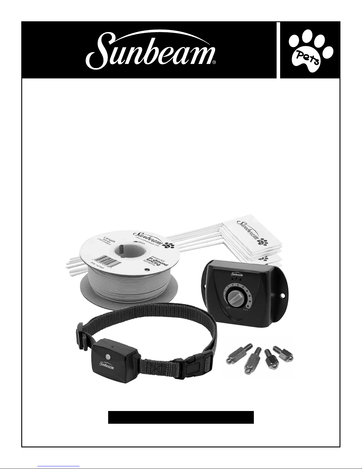
essential
in-ground
fencing
system
INSTRUCTION MaNUal
STaTIC

table of contents
IMPoRtant safeGUaRDs ......................................................................... 3
KeyWoRD DefInItIons ........................................................................... 4
Items You May Need .......................................................................................4
PRoDUct oveRvIeW............................................................................... 5
HoW It WoRKs
..................................................................................... 7
oPeRatInG InstRUctIons
...................................................................... 7
Planning Your Layout ........................................................................................7
Setting Up the Base Transmitter .............................................................................10
Testing the System ..........................................................................................11
How to Twist Wire ...........................................................................................12
How to Splice Wire ..........................................................................................13
Installing the Boundary Wire ................................................................................14
Using an Existing Fence .....................................................................................14
To Cross Driveways & Pathways .............................................................................14
Connecting & Testing The System............................................................................15
Setting the Boundary Width .................................................................................16
Setting Up the Boundary Flags ..............................................................................17
Receiver Collar ..............................................................................................17
Battery Installation ..........................................................................................17
Collar Fitting ................................................................................................18
Ready to Use................................................................................................19
Special Operating Notes.....................................................................................19
tRaInInG GUIDe
. . . . . . . . . . . . . . . . . . . . . . . . . . . . . . . . . . . . . . . . . . . . . . . . . . . . . . . . . . . . . . . . . . . . . . . . . . . . . . . . . . 20
Overview ...................................................................................................20
Common Stress Signals .....................................................................................20
Lesson #1 – Boundary Flag Awareness .......................................................................21
Lesson #2 – Static Correction ................................................................................22
Lesson #3 – Adjusting to Distractions ........................................................................23
Lesson #4 – Taking Your Dog O Leash.......................................................................24
Lesson #5 – Unsupervised Freedom .........................................................................25
Lesson #6 – Removing the Flags .............................................................................25
caRe anD MaIntenance
.......................................................................26
fcc stateMent
...................................................................................26
1 yeaR WaRRanty
...............................................................................27
2

IMPoRtant safeGUaRDs
ReaD all InstRUctIons befoRe Use. save tHese InstRUctIons foR fUtURe RefeRence.
• Thisproductshouldbeusedasacontainmentsystem.Forusewithdogsonly.Neverusethisproductforany
purposenotspecicallydescribedinthismanual.
• Donotserviceorinstallthissystemduringastorm.
• DonotinstalltheBaseTransmitterwhereitisexposedtotheweather.DonotplacetheBaseTransmitterin
anareawheretemperaturesfallbelowfreezing.DonotplacetheBaseTransmitterwithinthreefeetofany
appliancesorlargemetalobjects.Thiswillvoidthemanufacturer’swarranty.
• UsethelowestsettingpossibleontheReceiverCollartogetthedesiredresults.
• Regularlycheckthesystemtoensureitisworkingproperly.
• Complywithallwarningsinthismanual.
• Ifyouhaveanyreasontobelievethatyourdogmayposeadangertoothers,orthatitmightinjureitselfifitis
keptfromcrossingtheBoundaryWire,youshouldnotusethisproductsolelytocontainyourdog.
• NeverattempttosetupthisproductwhiletheReceiverCollarisonthedog.
• NevercallorforceyourdogintotheBoundaryZone.
• NeverattempttoworkonorxtheBaseTransmitterorBoundaryWirewhiletheBaseTransmitterispluggedin.
• Thisproductisnotatoy;keepoutofreachofchildren.
• Thisproductisnotintendedtocontainorprovideprotectionagainstaggressivedogs.
• Yourdogshouldbeingoodhealthwhenusingthisproduct.
• Thisproductisnottobeusedondogslessthan9lbs.
• Thisproductisnottobeusedondogslessthan6monthsold.
• AlwaysremovetheReceiverCollarpriortowashingorgroomingyourdog.
• AvoidleavingtheReceiverCollaronthedogformorethan8continuoushoursperday.Prolongedcollaruse
cancausepressuresoreswhichmayleadtoskinirritationsuchascontactdermatitisordecubitusulcers.Ifa
rashisdiscovereddiscontinueuseuntiltheskinareahealscompletely.Ifconditionpersistsformorethan48
hours,contactyourveterinarian.
• DonotattachaleashtotheSunbeam®ReceiverCollar.Aseparate,non-metalliccollarorharnessmaybeused
provideditdoesnotinterferewiththeSunbeam®ReceiverCollar.
• Warning:TheReceiverCollarusestwoLithium(CR2032)cointypebatteries.Keepthebatteriesoutofreachof
children.Ifswallowed,immediatelyseekmedicalhelpasseriousinjurymayoccur.
• TheLithiumcoinbattery(s)usedinthisproductcontainsperchloratematerial.Specialhandlingmayapplyin
California.Goto:www.dtsc.ca.gov/hazardouswaste/perchlorateformoreinformation.
• IMPORTANT: Eachdogwillhaveitsowntolerancelevel,behavioralcharacteristicsandindividual
environments;therefore,thereisnowayofknowingwhetherorhowyourdogwillreacttothisproduct.Ifyour
doghasanaggressivetemperamentorhaseverexhibitedaggressivebehavior,donotusethisproductuntil
youhavecontactedacertieddogbehaviorist.
3

KeyWoRD DefInItIons
• Base Transmitter: Sends the radio signal through the Boundary Wire.
• Boundary Flags:Avisualaidforthedog.TheBoundaryFlagswillremindthedogwheretheBoundaryZone
is located.
• Boundary Zone:TheBoundaryZoneistheareabeyondtheBoundaryFlagswherethedogwillreceiveaStatic
Correction.ThedogwillhearaWarningToneasitapproachestheBoundaryZoneandwillreceiveaStatic
CorrectioniftheydonotreturntotheSafeZoneimmediately.
• Boundary Wire: The wire that gives o a radio signal when the Base Transmitter is powered on.
• Exclusion Zones:Areasinyourlayoutsuchasgardens,poolsorotherlawndecorations,thatyouwantto
protect.Youcanexcludetheseareasfromyourlayoutwhilestillgivingyourdogaccesstoyouryard.
• Receiver Collar:ThedogwearstheReceiverCollar,whichreceivestheradiosignalfromtheBoundaryWire.
TheReceiverCollarwillemitaWarningTonewhenthedognearstheBoundaryZone.Ifthedogcontinuesto
theBoundaryZonethecollarwillemitaStaticCorrection.
• Safe Zone: TheareawherethedogcanroamwithoutreceivingaWarningToneorStaticCorrectionfromthe
Receiver Collar.
• Safe Spot: An area where there is Twisted Wire and the dog can walk through without receiving a warning or
Static Correction.
•Twisted Wire: Twisted Wire is used in your layout where you want to cancel out the signal. This means your
dogcanpassthroughtheseSafeSpotswithoutreceivingaStaticCorrection.Themostcommonareaforthe
SafeSpotisthearearunningfromyourBaseTransmittertothemainloopofyourBoundaryZone.
• Static Correction:AstaticpulseemittedfromtheReceiverCollar.
• Test Light:TheprovidedtoolusedtotesttheconnectionbetweentheReceiverCollarandtheBoundaryWire.
YouwillusetheTestLightwhencreatingyourBoundaryZone.
• Warning Tone:AsthedogapproachestheBoundaryZoneitwillhearaWarningToneemittedfromthe
ReceiverCollartoalertthedogtomoveawayfromtheBoundaryZone.
ITEMS YOU MAY NEED
-Gridpaperandpencil
-Ruler
-Level
-WireCutter/Stripper
-PhillipsHeadScrewdriver
-Shovel
-Scissors
-Lighter(optional)
-StapleGun(optional)
4

BATTERY DOOR:
Located on bottom of unit
for battery installation
and removal
FlashingRed:Lowbattery
Level Beeps GreenLEDLight
1-low 1shortbeep 1ash(repeated6times)
2-medium 2shortbeeps 2ashes(repeated6times)
3-high 3shortbeeps 3ashes(repeated6times)
correction level settings
MAIN CONTROL
BUTTON:
• On/O
• Correction
level adjustment
• LED
ADJUSTABLE
BUCKLE
QUICK RELEASE
CLASP
FABRIC
COLLAR
Do not Use tHIs fencInG systeM
UntIl yoU Have ReaD tHese InstRUctIons
PRoDUct oveRvIeW
5
STAINLESS STEEL PROBES:
Correction administering system
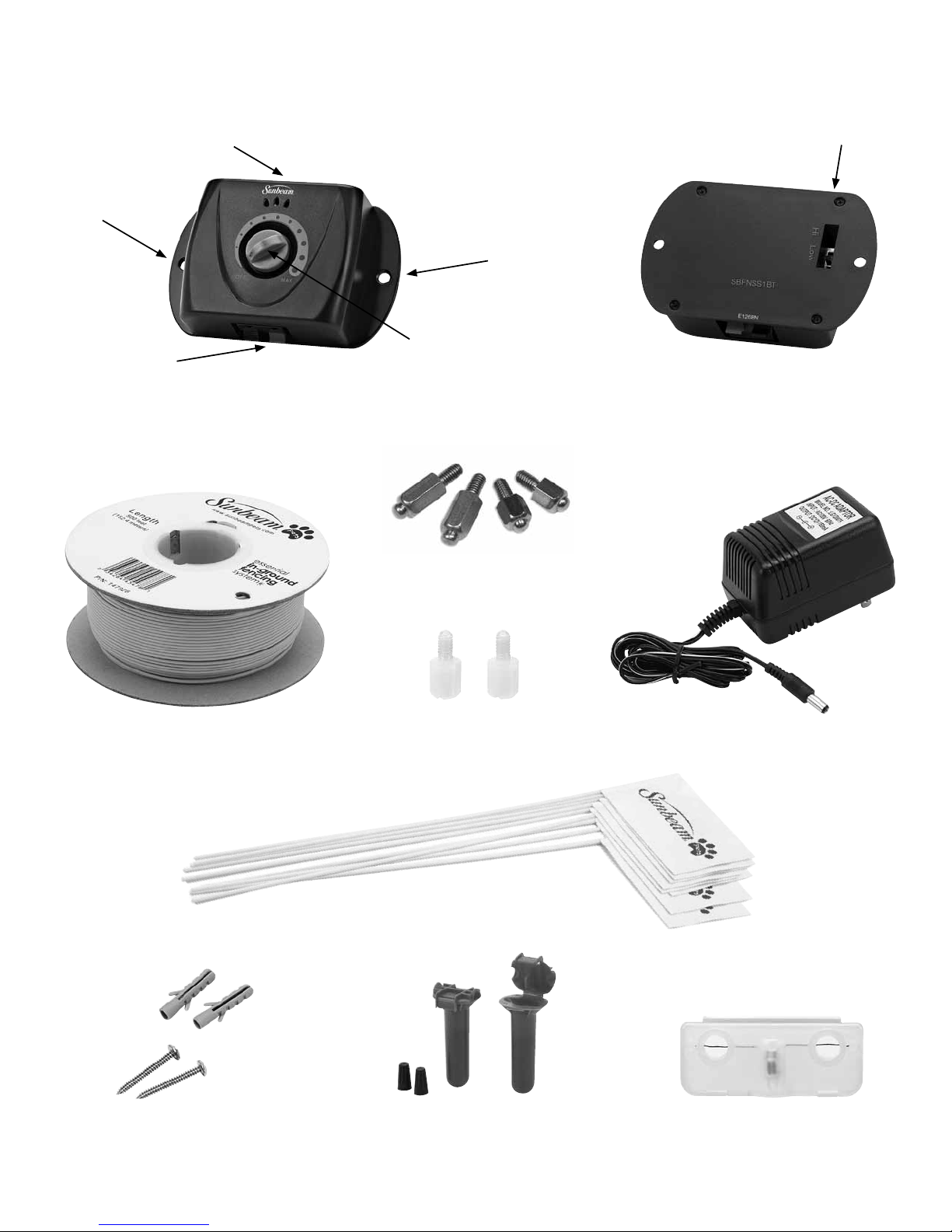
POWER INDICATOR:
(only the middle LED with light up)
• Solid green LED: Base Transmitter ON
• Flashing green LED: Connection problem
MOUNTING
HOLE
BASE TRANSMITTER
(Front)
SPRING-LOADED
BOUNDARY WIRE
CONNECTORS
BOUNDARY zONE
CONTROL KNOB
BASE TRANSMITTER
(Back)
YARD SWITCH:
• HI setting recommended for large yards
• LO setting recommended for small yards
SET OF 50 BOUNDARY FLAGS
TEST LIGHTWIRE SPLICING SUPPLIESMOUNTING HARDWARE
MOUNTING
HOLE
6
BOUNDARY WIRE PLASTIC PROBES AC ADAPTER
LONG AND SHORT
STAINLESS STEEL PROBES

7
HoW It WoRKs
TheSunbeam®EssentialIn-GroundFencingSystemisatrainingaidthathelpstrainyourdogtostaywithinadened
boundary.TheSystemusesawiretocreateaBoundaryZonewhereyourdogwillreceiveaWarningToneandaStatic
Correction.FlagsarearrangedalongtheBoundaryZonetogiveyourdogavisualaid.Theareaencompassedbythe
BoundaryFlagsistheSafeZone.TheSafeZoneistheareawhereyourdogcanroamwithoutreceivingaWarningTone
orStaticCorrectionfromtheReceiverCollar.TheBoundaryFlagscanberemovedattheendofthetrainingprocess.
TheSunbeam®EssentialIn-GroundFencingSystemusestheburiedwiretobroadcastaradiosignal.Theburiedwire
actsasanantennaconvertingthesignalintoelectromagneticwaves.TheBaseTransmittercontrolstherangeofthe
signalaroundthewire.InsidetheSunbeam®EssentialReceiverCollarisasmallradioreceiver.Whenthedogmoves
closetotheBoundaryZone,theReceiverCollarwillreleaseaWarningTonesoyourdogknowsitisnearingthe
BoundaryZone.IfyourdogmovesintotheBoundaryZone,itwillreceiveaStaticCorrection.
ToachievethebestresultswiththeSunbeam®EssentialIn-GroundFencingSystem,itisimportantthatyoucomplete
thetrainingthatfollowsintheincludedtrainingmanual.Ifyouhavemultipledogsadditionalcollarscanbeaddedto
yoursystem.ContacttheretailerfromwhichyoupurchasedtheIn-GroundFencingSystemorcall866-537-2249.
oPeRatInG InstRUctIons
WARNING: To avoid injury make sure there are no buried electrical cables in the surrounding area where you will
lay your Boundary Wire. Electric power lines, natural gas pipelines, communications lines and other utility services,
if damaged, can create a hazard that could endanger you and your property. Call your local utility company before
you dig to identify whether you have underground lines in the area where you want to lay your Boundary Wire. If
there are utility lines in the area, do not install this product and seek assistance from a trained electrician.
PlannInG yoUR layoUt
• Ongridpaper,sketchyourpropertymarkinganybuildings,driveways,undergroundlines,gardensorotherobstacles.
• Decidewhichareasofyourpropertyyouwanttogiveyourdogaccessto.
• Marktheareasofyourpropertythatyouwanttoexclude(suchasgardens,pools,etc.).Theseareasaredenedas
ExclusionZones.
• DeterminewhereyouwillinstalltheBaseTransmitter.InstalltheBaseTransmitterindoorsinadry,wellventilated
areawheretemperaturesdonotfallbelowfreezingandnearapoweroutlet.
• EstablishwhereyouwilllayyourBoundaryWire.TheBoundaryWiremustmakeacompleteloopstartingand
ending at the Base Transmitter. Twisting the Boundary Wire will cancel out the signal and allow your pet to pass
that area receiving no warning or correction. Mark on your layout where you will use Twisted Wire. Read more
aboutHowtoTwistWireonpage12.

• TheBoundaryWireshouldturncornersgradually.Avoidsharpturnsasthismaycanceloutthesignal.
• Ifyouhavemorethan1/3acreofpropertyyouwillneed
additional Boundary Wire to expand your main loop. The wire
chartwillhelpyoudeterminehowmany500ft.BoundaryWire
spoolsyouwillneed.Thechartisbasedonasinglelooplayout.
Thereisone500ft.BoundaryWirespoolincludedinyourkit.
•Whenyouhavedecidedontheamountofwireyouwillneedfor
yourchosenlayout,addanadditional20%toarriveatyourtotal
amountofwire.Addingtheextra20%willmakesureyouhave
enoughwiretoallowforsomeslackwhenyoulayyourwire.
Addingtheextra20%willalsoallowforanyerrorsincalculation
or unanticipated layout changes.
CHOOSE YOUR LAYOUT
Itisimportanttochoosetherightlayoutforyourfencingsystem.Usethesinglelooplayoutwhenallowingyour
dogaccesstotheentireproperty.Usethedoublelooplayoutwhenyouwanttorestrictyourdogtooneportion
ofyourproperty.EitherlayoutwillallowyoutosetExclusionZones.TocreateExclusionZonesyoumusttwist
theBoundaryWire.ReadmoreaboutHowtoTwistWireonpage12.Thefollowingsectionincludesdescriptions
anddiagramsofdierentlayouts,ExclusionZonesandstepstousinganexistingfence.
NOTE:ThisproductshouldNOTsolelybeusedtoprotectyourdogfromleavingtheSafeZone.
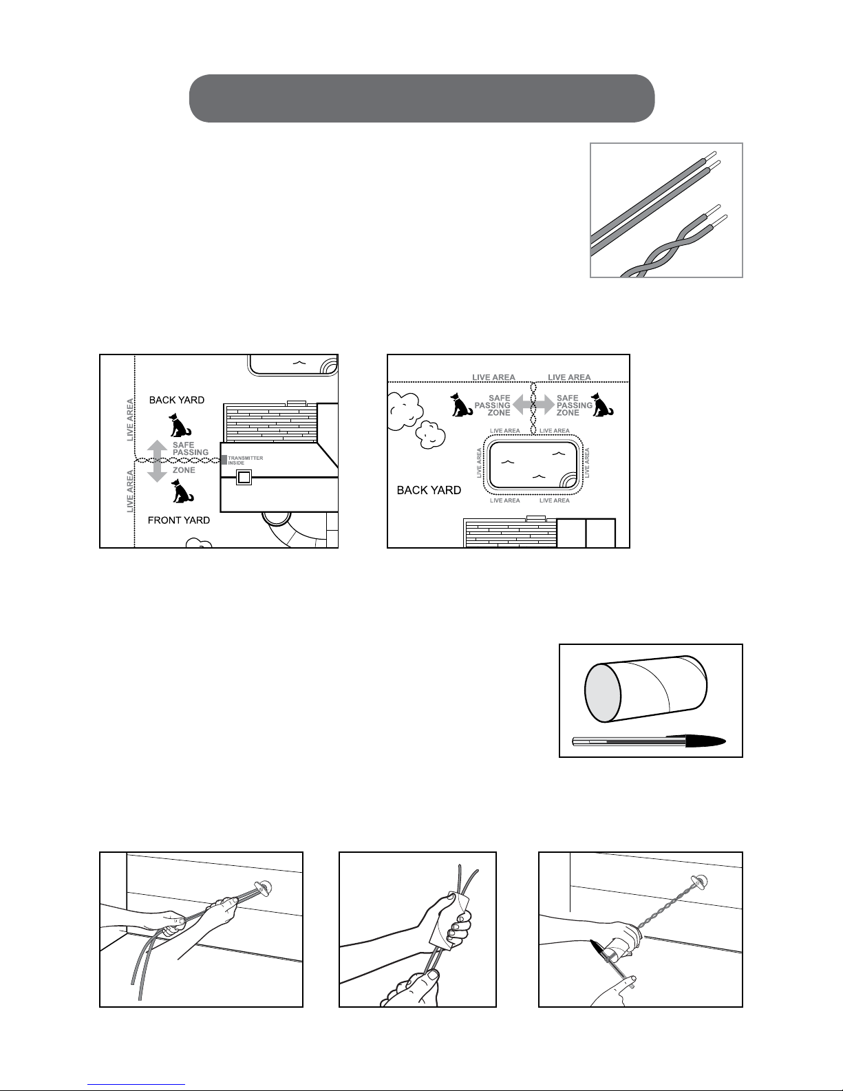
Perimeter Single Loop Layout
Thislayoutrunsalongtheperimeterofyourpropertyallowingyourdog
access to the entire property. You should lay the Boundary Wire a signicant
distancefromtheroad.Youshouldallowatleastthreeyardsbetweenyour
houseandtheBoundaryWiretoallowthedogtopassfromthefrontyard
tothebackyard.TwistingthewireneartheBaseTransmitter(asshown
inthediagram)willallowyourdogtopassovertheTwistedWirewithout
receiving a warning or Static Correction.
Hourglass Single Loop Layout
Thislayoutcontainsthedoginboththefrontandbackyard,butrestricts
theaccessbetweenthefrontandbackyardstoppingthedogfromcrossing
inbetween.
Acres Wire Needed # of Spools
¼ 415 ft. 1 (included)
¹/3480 ft. 1 (included)
½ 590 ft. 2
1 835 ft. 2
2 1,180 ft. 3
5 1,870 ft. 4
wire chart
Hourglass Single Loop
8
Perimeter Single Loop
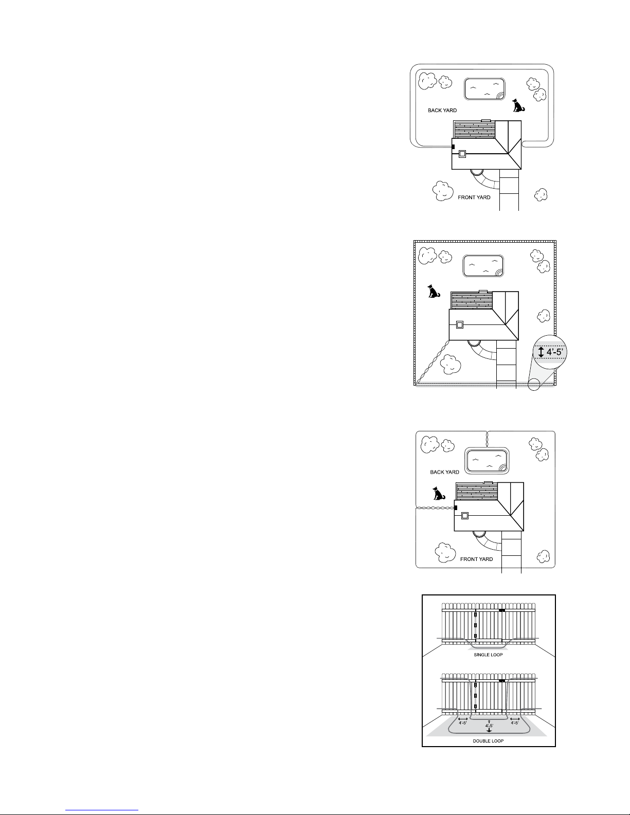
Double Loop Layout
Thislayoutallowsyourdogaccesstoaportionoftheyardthatyouchoose.
YoushouldlaythetwoparallelBoundaryWiresatleast4to5feetapartto
avoidinterferenceandcancelingthesignal.
Single Side Boundary Double Loop Layout
IMPORTANT: This layout is not recommended unless the property
is fenced on the rest of the sides as shown in the diagram.
Thislayoutallowsyoutocreateasinglesidedbarrier.Youshouldrun
BoundaryWirefromtheBaseTransmittertotheareawhereyouwant
tocreatetheboundary.CreatealongloopofBoundaryWirewhereyou
wanttocreatethebarrier.Makesuretheloopislongenoughsothat
thedogcannotgoaroundit.Makesurethatthereisatleast4to5feet
betweentheparallelBoundaryWirestoavoidinterferenceandcanceling
thesignal.UseTwistedWireintheareathatleadsbacktotheBase
TransmittertomakethisareapartoftheSafeZone.
Exclusion Zones
YoumayhaveareasoftheSafeZonethatyoudonotwantyourdogto
access.Theseareascanincludeapool,gardenorotherlawndecorations.
YoucanaddExclusionZoneswhilestillgivingyourdogfullaccesstothe
property.TocreateanExclusionZoneloopBoundaryWirearoundthe
area you want to protect and join the loop to the main loop with some
Twisted Wire.
Using an Existing Fence
Youcanutilizeanexistingfencetocreateyourlayout.Readmoreabout
Installing the Boundary Wire on page 14.
9
Double Loop
Exclusion Zone
Single Sided Boundary Loop

settInG UP tHe base tRansMItteR
IMPORTANT:TheBaseTransmittershouldbeplacedinadry,wellventilatedareaindoors.DonotplacetheBase
Transmitterinanareawheretemperaturesfallbelowfreezing(g.1).DonotplacetheBaseTransmitterwithin3
feetofanyappliancesorlargemetalobjects(g.2).ACadaptorisforindooruseonly.
TheBaseTransmittercreatesthesignalthatgoestotheBoundaryWiretocreatetheBoundaryZone.Fromthe
BaseTransmitteryoucontroltheBoundaryZoneArea(thedistancefromthewirewherethewarningsignal
andcorrectionbegins).TheBoundaryWiremustrunfromtheBaseTransmittertooutside.Itisrecommended
youmounttheBaseTransmittertotheinsideofanexteriorwallsoyoucaneasilyruntheBoundaryWire
outside.Remember,theBoundaryWiremustbeginattheBaseTransmitterandmakeacontinuousloopback
to the Base Transmitter.
OnthebackoftheBaseTransmitterthereisaYardSwitch(g.3).ThedefaultsettingisHi.Usethissettingtotest
thesystembeforeyoumounttheBaseTransmittertothewall.IftheBoundaryZoneistoobig,adjusttheYard
Switch to Low.
10
OFF
MAX
gure 1 gure 2
gure 3
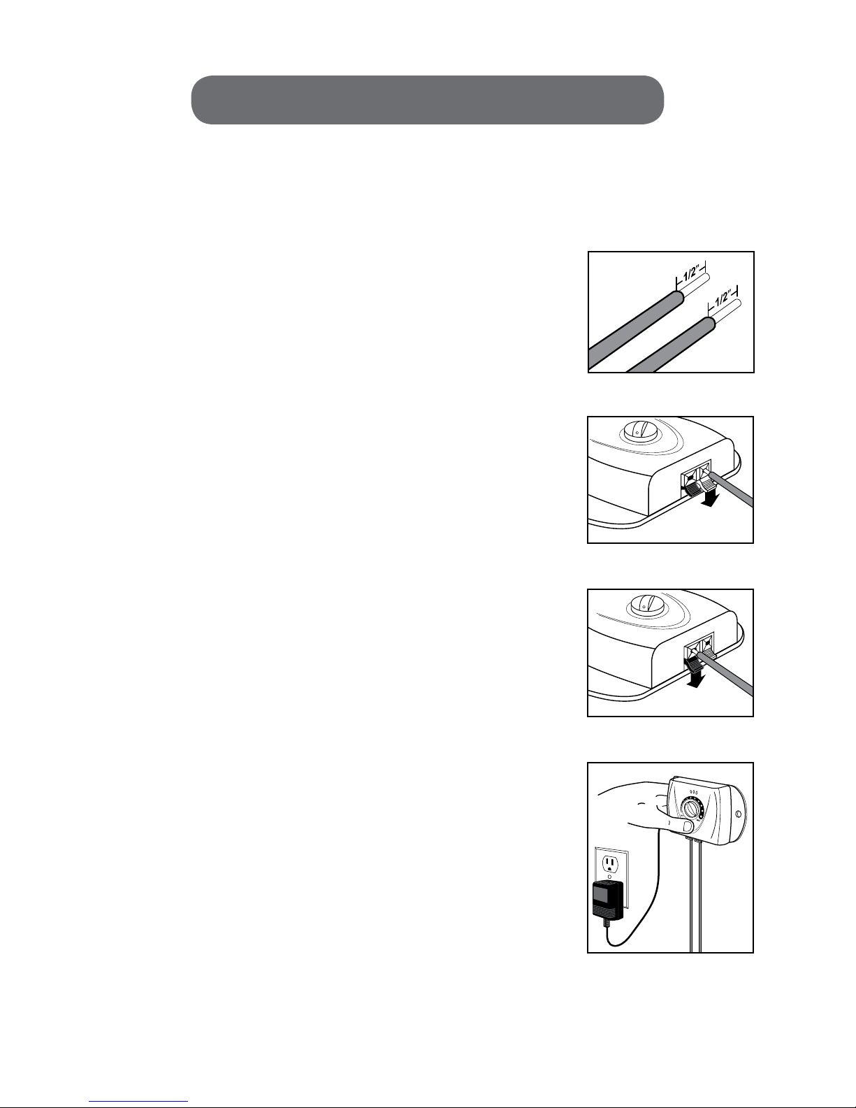
testInG tHe systeM
AfteryouhavesketchedoutyourlayouttestthesystempriortoburyingtheBoundaryWire.LayyourBoundary
Wirefollowingyourplanneddesign.BecarefulwhenyoulayouttheBoundaryWireasanydamagewillaect
thesignalstrengthoftheInGroundFence.
• LayouttheBoundaryWireabovegroundfollowingyourplanneddesign.Addabout20%extraBoundaryWire
toallowforburying.
• UsethesuppliedBoundaryWirefortheareasyoudonotwantyourdogtopass.
• Usetwistedpairwireintheareaswhereyouwanttocanceloutthesignaland
allowyourdogtosafelywalkthrough.ReadmoreaboutHowtoTwistWire
on page 12.
• Onceallofthewiresarelaidoutsplicethepiecestogether,ifnecessary,to
createacontinuouswire.ReadmoreaboutHowtoSpliceWireonpage13.
• Usingawirestripper,stripaboutonehalfinch(½”)ofthecoatingfromthetips
oftheBoundaryWiretoexposeclean,non-corrodedBoundaryWire.(g.4)
• IMPORTANT: Do not insert the Boundary Wires into the Base
Transmitter while it is plugged in.
• InsertoneendoftheBoundaryWireintotheblacktabonthebottom
oftheBaseTransmitterbypullingbacktheblacktab.(g.5)
• InserttheotherendoftheBoundaryWireintotheredtabonthebottom
oftheBaseTransmitterbypullingbacktheredtab.(g.6)
• InserttheACadaptorintotheBaseTransmitterandplugtheACadaptor
intoapoweroutlet.(g.7)
• TurnontheBaseTransmitterbyturningtheBoundaryZoneknobtothe
right. You will see the green LED power indicator light up when the system
hasbeenturnedon.IfthegreenLEDblinksthereisadisconnectioninyour
main loop. You should unplug the system until you have identied the
locationofthedisconnection.
• Forthepurposeoftesting,turntheBoundaryZoneknoballtheway
to MAX.
11
gure 4
gure 5
gure 6
gure 7
12
HoW to tWIst WIRe
Twisting two Boundary Wires together causes the radio signal to cancel out. The
BoundaryWireshouldbetwisted10to12timesperfoottocancelthesignal.In
theareaswhereyouinstallTwistedWireyouwillcreateaSafeSpotwherethedog
canwalkwithoutbeingcorrectedbytheReceiverCollar.Forexample,thewire
thatconnectstheBaseTransmittertoyourouterBoundaryWireshouldbeTwisted
Wire and should not warn or correct your dog. Mark on your plan layout where
yourTwistedWireislocatedforfuturereference.
TwistedWirecannotbepartofyourmainloop.ThemainpurposeforTwistedWireistojointhemainlooptotheBase
Transmitter(g.8).YoucanalsouseTwistedWiretoconnecttheExclusionZonestothemainBoundaryWire(g9).
CREATE TWISTED WIRE
YoucancreateTwistedWirebyusinghouseholditemssuchasanempty
toilet paper holder and a pen or a PVC pipe and a socket wrench.
• Loopthewirearoundananchorpoint.(g.10)
• Insertthewireintothecylinderandthreadthroughtheotherend.(g.11)
• Attachtheendofthewiretoapenorasocketwrench.
• Twistthewireuntilyoufeelthewireistwistedenoughthatitwillnot
untwistwhenreleased.(g.12)
• Releasethewirefromthepenorsocketwrench.Whenyourstreleasethewireitwillunravelalittlebit.
gure 8 gure 9
gure 10 gure 11 gure 12
13
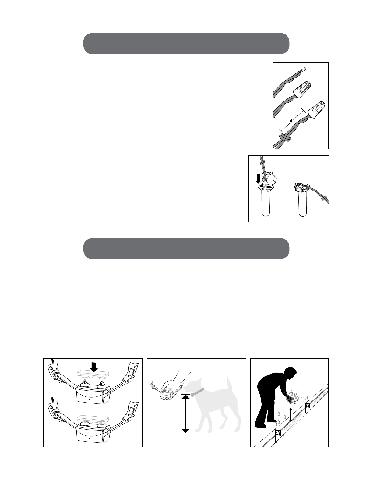
HoW to sPlIce WIRe
IfyouareusingTwistedWireoradditionalBoundaryWiretoexpandyourmainloop,
you will need to splice the wires together. Mark on your plan layout where your wire
splicesarelocatedforfuturereference.Yoursystemshouldnotbe
energizedwhensplicingthewires.
• Usingawirestripper,stripaboutonehalfinchofthecoatingfromthetipsof
theBoundaryWiretoexposeclean,non-corrodedBoundaryWire.
•Holdthewirestogether.Insertthewiresintothesuppliedwirenutensuringthat
thereisnocopperexposedbeyondtheendofthewirenut.Twistthewirestogether
in a clockwise direction. Pull lightly on the wire nut to make sure it is secure.
•Tieaknot4inchesfromthewirenut.
• Openthetopofthegreasetubeandinsertthewirenut.Closethecapon
thegreasetube.Thiswillwaterproofyourwiresplice.
testInG tHe systeM cont.
In order to make sure the system is working properly you must test the wire using the Receiver Collar. Install the
batteries(seepage17BatteryInstallation)andturntheReceiverCollaronbypressingandholdingfor4seconds
until the LED indicator lights up. Do not test the system while the Receiver Collar is on your dog.
• PlacetheTestLightindentationholesdirectlyontotheReceiverCollarstainlesssteelprobes.(g.13)
• SlowlybringtheReceiverCollarneartheBoundaryWireatyourpet’snecklevelwithprobesfacingup(g14).Ifthe
system is working correctly you will hear a Warning Tone. Continue toward the Boundary Wire until you see the Test
Lightash(g.15).IfyoudonotheartheWarningToneorseetheashyoushouldreviewthepreviousdirections.
• Ifyoursystemisworkingcorrectly,unplugtheBaseTransmitteranddisconnectthewiresfromtheBase
TransmitterandcontinuetofollowthedirectionsoninstallingtheBoundaryWire.
gure 13 gure 14 gure 15

14
InstallInG tHe boUnDaRy WIRe
TheBoundaryWireisburiedtoprotectitfrombeingdamaged.IftheBoundaryWireisdamagedyouriskhaving
gapswheretherecouldbepoorsignalstrengthinyourInGroundFence.
• Usingashovel,diganarrowtrenchalongyourplannedBoundaryZonewhereyouwilllayyourBoundary
Wire.Thetrenchshouldbeabout3to6inchesdeep.Useablunttoolsuchasawoodenpaintsticktopushthe
boundarywireintothetrench.Becarefulnottodamagetheboundarywireinsulation.
• PlacetheBoundaryWireintothetrenchandburythewire.Itis
recommended that you lay your Boundary Wire in one yard sections.
Make sure you allow some slack when laying the Boundary Wire
toallowforexpansionandcontractionwithtemperaturevariations.
• Covertheareawhereyouburiedthewireandtaponthesurface
lightly to secure.
• Ifyouarecreatingadoublelooplayout,makesuretheparallel
BoundaryWireisseparatedby4to5feet.
UsInG an exIstInG fence
Youcanuseanexistingfenceaspartofyoursingleordoublelooplayout.
IfyouareusingadoublelooplayoutyoushouldrunthetwoparallelBoundaryWiresatleast4-5feetaparttoavoid
interferenceandcancelingthesignal.
Atagateopening,burythewireinthe
ground under the gate. Ensure you are
maintainingthe4to5feetseparation
intheBoundaryWireifyouareusinga
doubleloop.Rememberthatyourdog
cannot pass through the gate as the
signalisstillactive.(g.16)
There are dierent methods used
to secure the Boundary Wire to the
fence.Themethodisbasedonthe
typeoffenceyouhave.(g.17)
Wooden Fence:Usingastaplegun,stapletheBoundaryWiretothefence.AvoidpuncturingtheBoundaryWire
as this will damage the system.
Chain Link Fence:WeavetheBoundaryWirethroughthelinksanduseplasticziptiestosecurethewire.
Vinyl Fence:ContactyourfencemanufacturerorretailerforbestmethodtosecuretheBoundaryWiretothefence.
to cRoss DRIveWays & PatHWays
IfyourBoundaryZonerequiresyoutocrossaconcretedrivewayorsidewalkconsultaprofessional.
STAPLE WIRE TO FENCE
STAPLE WIRE TO FENCE
WEAVE WIRE INTO FENCE
gure 16 gure 17
15
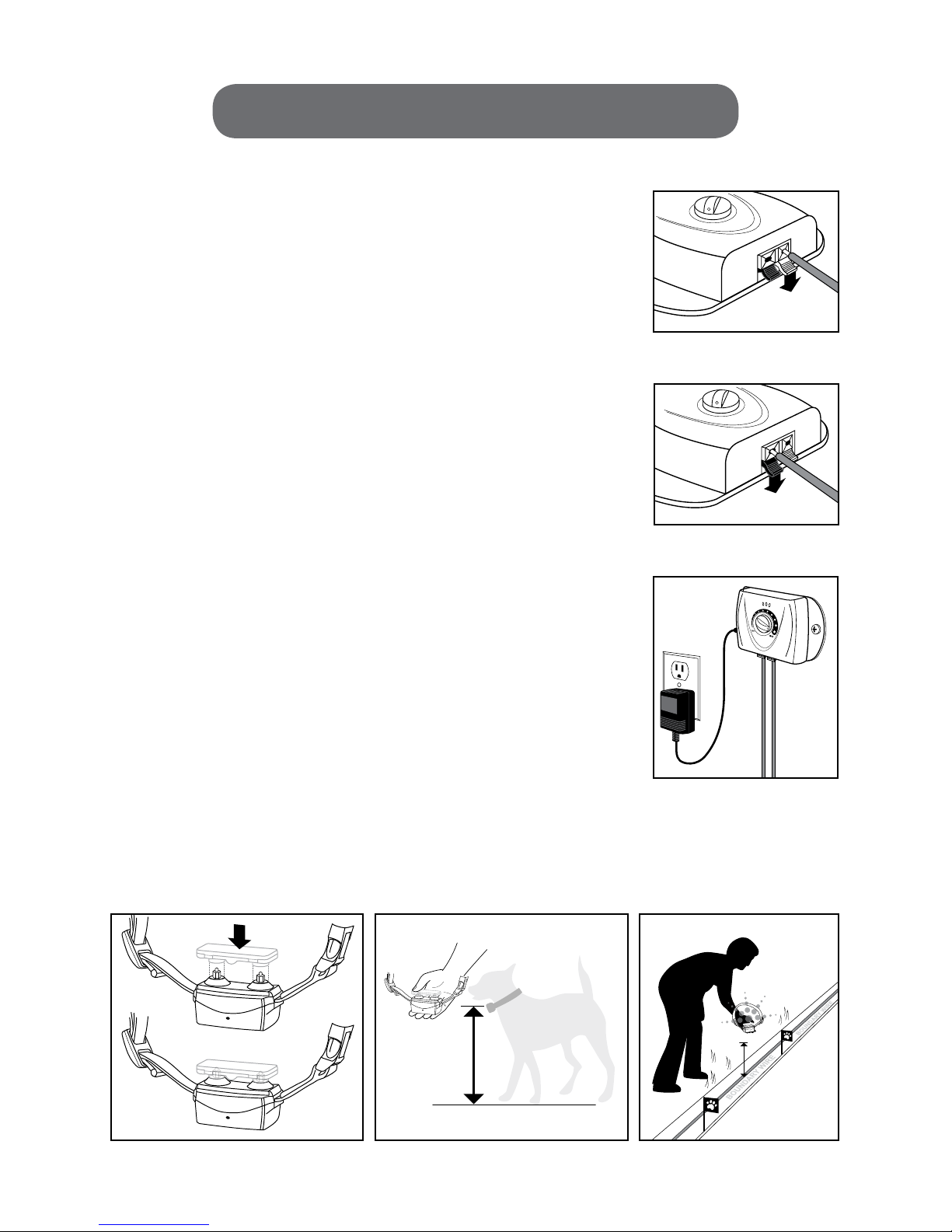
connectInG & testInG tHe systeM
• UsearulertomeasurethedistancebetweenthemountingholesonthesidesofyourBaseTransmitter.TheBase
Transmittermustmounttoastationarysurface.
• UsingthemountingholesonyourBaseTransmitterasamountingtemplate,
use a level and a ruler to mark on your wall where the screws will go.
• UsingaPhilipsheadscrewdrivermounttheBaseTransmitterdirectlyinto
thewall.Ifyouarenotmountingdirectlyintothewallstud,installthescrew
anchorssuppliedbeforeattachingthetransmittertothewall.
• TheBoundaryWiremustruntotheoutsidewhereyouwilllayoutyoursystem.
MakesurethattheBoundaryWireisnotbeingpinchedbyanydoorsorwindows
asthiswilldamagethewire.Ifnecessary,youmayhavetodrillaholethrough
the wall.
• NOTE:EnsurethatthebaseTransmitterisunpluggedbeforeinsertingthe
Boundary Wires into the Base Transmitter.
• InsertoneendoftheBoundaryWireintotheblacktabonthebottomofthe
BaseTransmitterbypullingbacktheblacktab.(g.18)
• InserttheotherendoftheBoundaryWireintotheredtabonthebottom
oftheBaseTransmitterbypullingbacktheredtab.(g.19)
• InserttheACadaptorintotheBaseTransmitterandplugtheACadaptor
into a power outlet.
•TurnontheBaseTransmitterbyturningtheBoundaryZoneknobtotheright.
YouwillseethegreenLEDpowerindicatorlightupwhenthesystemhasbeen
turnedon.(g.20)
• Forthepurposeoftesting,turntheBoundaryZoneknoballthewaytoMAX.
• Inordertomakesurethesystemisworkingproperlyyoumusttestthewire
usingtheReceiverCollar.TurnontheReceiverCollarbypressingandholding
for4secondsuntiltheLEDindicatorlightsup.
• PlacetheTestLightholesdirectlyontotheReceiverCollarprobes.(g.21)
• SlowlybringtheReceiverCollarneartheBoundaryWireatyourpet’snecklevelwithprobesfacingup(g.22).Ifthe
system is working correctly you will hear a Warning Tone. Continue toward the Boundary Wire until you see the Test
Lightash(g.23).IfyoudonotheartheWarningToneorseetheashyoushouldreviewthepreviousdirections.
gure 20
gure 18
gure 19
gure 21 gure 22 gure 23
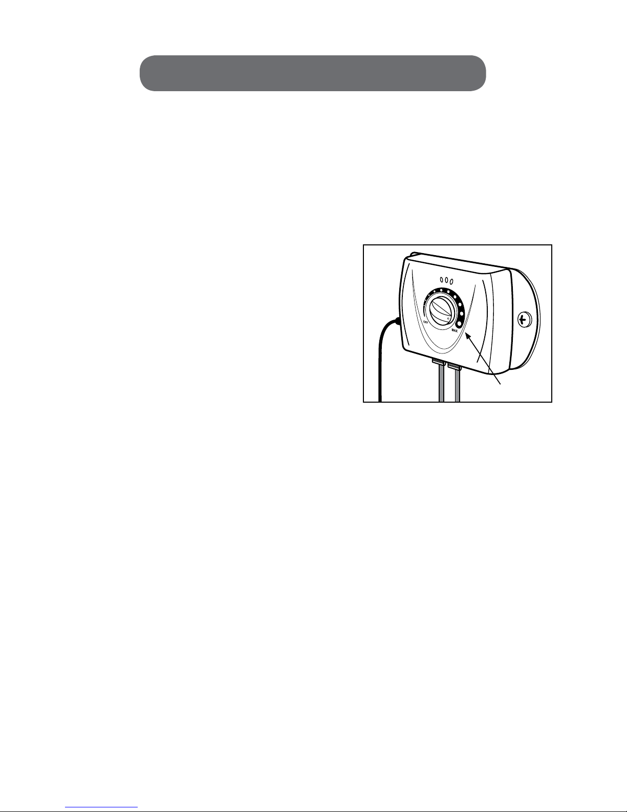
settInG tHe boUnDaRy WIDtH
TheBoundaryZoneistheareabeyondtheBoundaryFlagswherethedogwillreceiveaStaticCorrection.Thedogwill
hearaWarningToneasitapproachestheBoundaryZoneandwillreceiveaStaticCorrectioniftheydonotreturnto
theSafeZoneimmediately.YoushouldsettheBoundaryZonewidthaswideaspossibletogiveyourpetthelargest
warningandcorrectionzonewithoutreducingtheSafeZone.InitiallyconsideraBoundaryZonewidthofaminimum
of10feet.AsyourdogbecomesaccustomedtotheSystemyoumaybeabletoreduceyourBoundaryZonewidth.
YoucanadjusttheBoundaryZonebyturningtheknobontheBaseTransmitter.Asyouturntheknobtothe
rightyouareincreasingtheBoundaryZonewidth(howfarfromthewirethewarningandcorrectionbegins).
NOTE:Makesureyougivethedogatleast3feetofSafeZoneinallareas,payingspecialattentiontonarrow
areasonthesideofthehome.
• BeginwiththeBoundaryZoneknobturnedtoMAX.
• TurnyourReceiverCollaronandplacetheTestLight
indentationholesdirectlyontotheReceiverCollarprobes.
• ChooseasectionofstraightBoundaryWirethatisatleast
50feetlong.
• SlowlybringtheReceiverCollarneartheBoundaryWireat
yourpet’snecklevelwithprobesfacingup.Asyouapproach
theBoundaryZoneyouwillhearaWarningToneandtheTest
Lightwillash.TheWarningToneindicatesthebeginningof
theBoundaryZone.
• MeasurethedistancefromthespotwhereyouheardtheWarningTonetotheBoundaryWire.Thisdistanceis
yourBoundaryZone.RemembertheareaencompassedbytheBoundaryFlagsistheSafeZone.TheSafeZoneis
theareawherethedogcanroamwithoutreceivingaWarningToneorStaticCorrectionfromtheReceiverCollar.
• Testinseveraldierentareastomakesurethesystemisfunctioningproperly.
• YoucandecreasetheareaoftheBoundaryZonewidthbyturningtheBoundaryZoneknobtotheleftand
testing using your Receiver Collar and Test Light.
• RepeatthisexerciseuntilyouachievethedesiredBoundaryZonewidthandSafeZone.
• IfyouaresatisedwiththeBoundaryZonemoveontoSettinguptheBoundaryFlags.
16
settInG UP tHe boUnDaRy flaGs
• YoumustsetuptheBoundaryFlagsasavisualaidforyourdog.The
BoundaryFlagswillremindyourdogwheretheBoundaryZoneislocated.
• UsingtheReceiverCollarandTestLightasaguide,beginplacingyour
Boundary Flags at the point where you hear the Warning Tone. Space the
BoundaryFlagsaboutonetotwoyardsapartinsmallyardsandabouttento
fteenfeetapartinlargeyards.
• IfthereareareasoftheBoundaryZonewhereyoucannotplanttheags
intothegroundllasmallcanwithsand,placethelledcanontheedgeof
theBoundaryZoneandplacetheaginthesand.Repeatthisprocessuntil
youhavemarkedtheentireBoundaryZonewithBoundaryFlags.
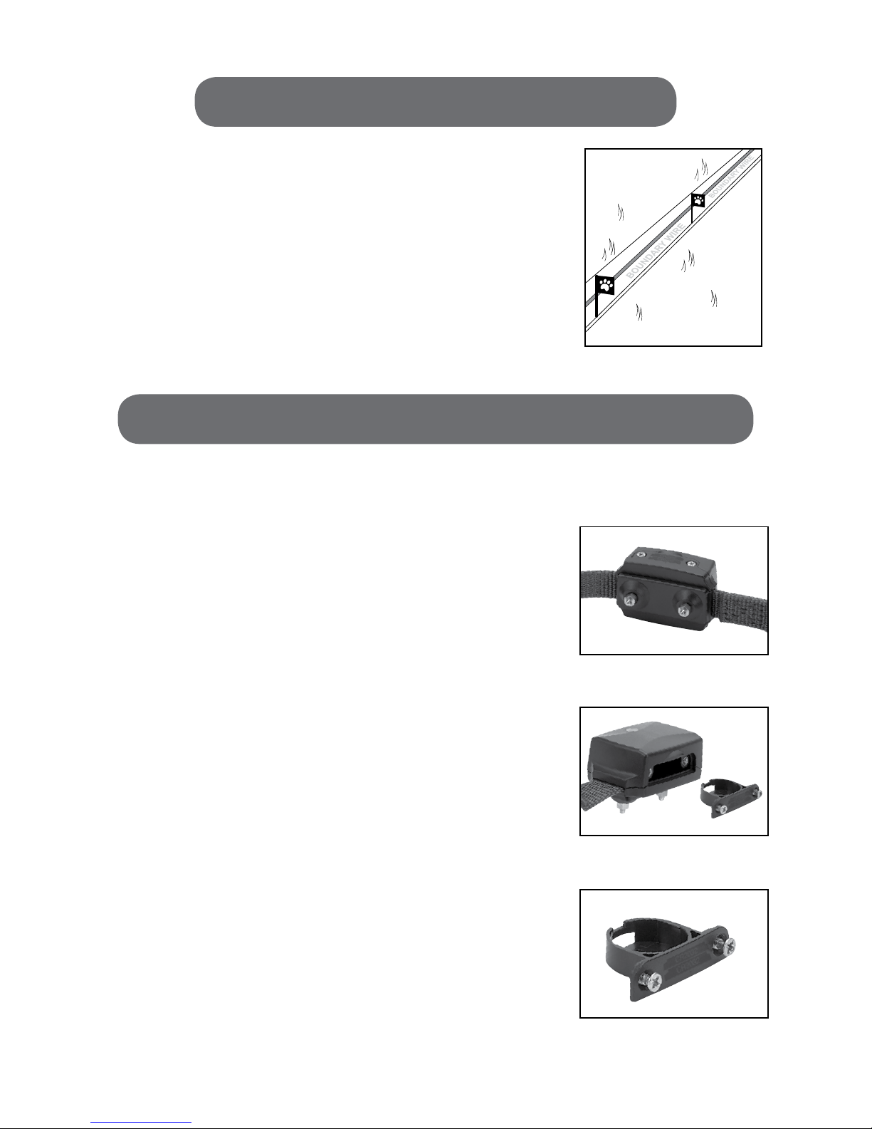
ReceIveR collaR oPeRatInG InstRUctIons
batteRy InstallatIon
IMPORTANT: This step is to be completed when the collar is NOT on your dog.
•Removetwoscrewssecuringthebatterycompartmentusingacrosshead
orPhillipsheadscrewdriver.(g.24)
•LiftbatterycompartmentfrommainbodyofReceiverCollar.(g.25)
•InserttwoCR2032Lithiumcoinbatteriesintobatterycompartment.
Batteriesshouldbeplacedwiththepositivesidefacingdown.
IMPORTANT: Follow orientation as described on graphics illustrated
on battery compartment. (g. 26)
•ReplacebatterycompartmentwithtwoCR2032Lithiumcoinbatteriesback
intomainbody.Note:Thebatterycompartmentcanonlybeassembledin
oneorientation,donotforceclosed.Seemarkingsonthebatterydoor.
•Tightenthetwoscrewsusingthecross-headscrewdriver,donotovertighten.
•Totesttheunitturnonbypressingandholdingthecontrolbuttonfor
4seconds.Youwillhearonelongbeepfollowedbyasequenceofshort
beepsandashinggreenLEDindicatingwhichcorrectionlevelisinuse.
TheReceiverCollarwillrecallthelastsettingorthedefaultsetting
(level1orlow).
•Toturnotheunit,pressandholdthecontrolbuttonfor4seconds.Youwill
hearshortbeepsindicatingthecurrentcorrectionlevelfollowedbyalong
beepindicatingtheunitiso.
•BeforereplacingbatteriesyoumustcompletelydischargetheReceiver
Collar. Be sure the unit is in the OFF position and place the metal portion
ofaplastichandlescrewdriveracrossbothstainlesssteelprobesfor
5seconds.Disposeofbatteriesperlocal,stateandnationallaws
and regulations.
17
gure 24
gure 25
gure 26

collaR fIttInG
PropertoftheSunbeam®ReceiverCollarisessentialtoestablishagoodtrainingfoundationandoptimalperformance.
NOTE: BatteriesshouldbeinstalledproperlyandtheReceiverCollarshouldbeintheOFFpositionbefore
proceeding with tting the collar to your dog.
STEP 1: Ensure dog is in a relaxed position.
STEP 2:Withthecollarclaspopenloosentheadjustmentbucklesuchthatitcan
reachcompletelyaroundyourdog’sneck.(g.27)
Whenbuckled,thecollarshouldrestdirectlybehindthedog’sears(thehighest
partoftheneck).(g.28)
Note:Makesurebothstainlesssteelprobesgothroughthecoatcompletelyand
make contact with the skin.
Usethelongerstainlesssteelprobesifthecoatdoesnotallowtheshorterprobes
to reach the skin.
Beforechangingthestainlesssteelprobesyoumustcompletelydischargethe
Receiver Collar. Be sure the unit is in the OFF position and place the metal portion
ofaplastichandlescrewdriveracrossbothstainlesssteelprobesfor5seconds.
Trimmingthehairaroundthedog’sneckwherethestainlesssteelprobes
willtouchtheskinisoptional,DONOTtrimthehairsoshortthattheskinis
completelyexposedasthismightallowforanirritationorrashtooccur.
Useawrenchwhenassemblingordisassemblingthestainlesssteelprobes,
donotovertighten.(g.29)
STEP 3: Closeandlockclasp.(g.30)
STEP 4: Adjustforpropertbypullingonstrapuntilyoucanttwongersin
betweenyourdog’sneckandthecollar.(g.31)
STEP 5: Letyourdogweartheproductforsucienttimeconrmingthattheyare
moving around normally. This step is to ensure that under daily activity the collar
willremainsecureandnotbecomeloose.
STEP 6: Removecollarfromdogandcuttheexcesscollarmaterial,leaving
approximately 1 inch.
STEP 7: Sealtheedgeofthecollarusingaame.
STEP 8: Reattachcollartoyourdog.Checkthetofthecollarseveral
timesperday.Wipethestainlesssteelprobesweeklywithadampclothwhile
collar is in OFF position.
Reminder: Ifyouchoosetousea2ndcollar,leashorharnesssystem,makesure
itdoesnotinterferewiththeoperationoftheSunbeam®ReceiverCollar.
18
gure 27
gure 28
gure 29
gure 30
gure 31
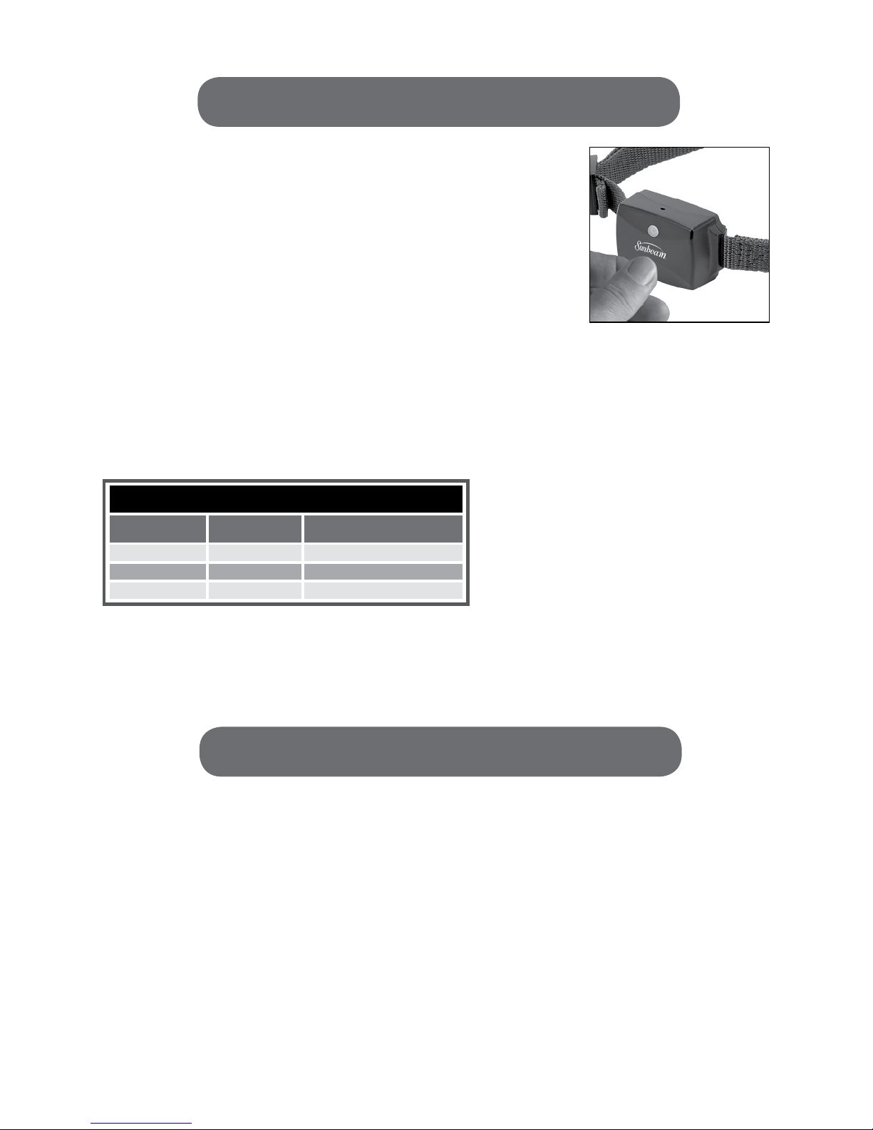
ReaDy to Use
Note:TheBATTERYINSTALLATIONandCOLLARFITTINGstepsmustbe
completedbeforeyouarereadytouse.
STEP 1:HoldingthemainbodyoftheSunbeam®ReceiverCollarinbothhands
PRESSandHOLDtheControlButtonfor4seconds.
Note:Youwillhearonelongbeepfollowedbyasequenceofshortbeepsand
ashing green LED indicating which correction level is in use. The Receiver
Collarwillrecallthelastsettingorthedefaultsetting(level1orlow).
STEP 2:Setcorrectionlevelbypressingandholding(approximately2seconds)
the Control Button.
Once the collar is ON press the Control Button once to toggle to the next correction level.
Note:ItisrecommendedtostartontheLOWsettingandmonitoryourdog’sbehaviorbeforedetermining
ifahighercorrectionlevelisneeded.
Thebelowtabledescribesthecorrectionlevelsettings.
STEP 3:AttachcollartoyourdogasyoudidintheCOLLARFITTINGstage.
sPecIal oPeRatInG notes
TheSunbeam®ReceiverCollarretainstheLASTcorrectionlevelsettingandwillresumethismodewhentheunit
is turned on.
LowBatteryMode:TheReceiverCollarLEDwillashREDfor5secondswhenthebatteryneedstobereplaced.
ReminderCorrection:WhenyourdogreachestheBoundaryZonetheywillreceiveaStaticCorrection.Ifyour
dogisstillintheBoundaryZonewhentheStaticCorrectionreachesthemaximumlimit,theReceiverCollarwill
administrate a Reminder Correction. The Reminder Correction is a very low Static Correction intended to remind
thedogtoleavetheBoundaryZone.
MultipleDogs:Ifyouhavemultipledogsadditionalcollarscanbeaddedtoyoursystem.Contacttheretailer
fromwhichyoupurchasedtheIn-GroundFencingSystemorcall866-537-2249.
19
FlashingRed:Lowbattery
Level Beeps GreenLEDLight
1-low 1shortbeep 1ash(repeated6times)
2-medium 2shortbeeps 2ashes(repeated6times)
3-high 3shortbeeps 3ashes(repeated6times)
correction level settings

20
tRaInInG GUIDe
oveRvIeW
It is important to read this section completely before beginning to train your dog to use the Sunbeam®
Essential In-Ground Fencing System. The System is not a solid fence and will not contain your pet as
well as a solid fence. Do not allow your dog to run free until the training process is complete. Keep your
dog on a leash, tied down, or conned to a separate area until training is complete. Proper training is
necessary to achieve the best results.
PriortouseofthesystemyourdogshouldweartheReceiverCollarwithoutturningiton.Thiswillallowthedog
tobecomecomfortablewearingthecollarandensurethecollartscorrectly.
•Thetrainingprocessshouldbeenjoyableforbothyouandyourdog.
•Trainingshouldbermandconsistent.
•Keepyourtrainingsessionsshort.Tentofteenminutetrainingsessionsthataredonefrequentlyare
recommended.Aseriesofshortsessionsisbetterthanfewerlongsessions.
•BeforetakingyourdogoutofthecontainmentarearemovetheReceiverCollarandturnito.
•Youmustcompletetheentiretrainingprocess.Althoughyourdogmaybea“quicklearner”,reinforcement
iscriticaltolongtermuseofthesystem.
•Ifyouhavemultipledogs,trainthemone-at-a-timeandbesuretokeepthedogsthatarenotbeingtrained
outofsight.
YouwantyourdogtobecompletelycomfortablewhentheyareintheSafeZone.Finisheachtrainingsession
withpositivereinforcementincludingpraiseandtreats.Toincreaseyourdog’scomfortlevelintheSafeZone,
spend5to10minutesofplaytimewithin10feetoftheBoundaryFlagsatthebeginningandendofeach
training session.
IMPORTANT: If your dog shows signs of stress you will need to slow down the training process. Go back
to a step where your dog feels comfortable and proceed slowly through the training process. Increasing
play time in the Safe Zone can also make the dog more comfortable.
Common stress signals include:
• Panting/Shaking/Overallnervousness •Bodyloweredorlyingdown
• Taildownand/orbetweenthelegs •Standingandfailingtomove
• Pullingontheleashtowardthehouse •Squintingeyes
• Earsgoingback
Table of contents
Other Sunbeam Pet Care Product manuals

Sunbeam
Sunbeam Easy Track Litter Box User manual

Sunbeam
Sunbeam SBCF01 User manual

Sunbeam
Sunbeam SBCF01 User manual

Sunbeam
Sunbeam Sonic Egg User manual

Sunbeam
Sunbeam SBRTSS1 User manual

Sunbeam
Sunbeam Bark Control Collar User manual

Sunbeam
Sunbeam Lighted Nail Trimmer User manual

Sunbeam
Sunbeam Bark Control Collar User manual

Sunbeam
Sunbeam Sonic Egg User manual

Sunbeam
Sunbeam remote trainer User manual


