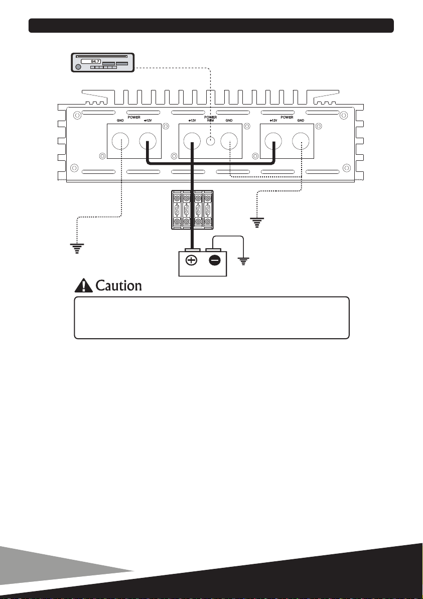
Sundown Audio SALT-4 User manual

OWNER’S MANUAL
Mono Blocks:
SALT - 4
SALT - 6
SALT - 8
SALT - 12
Multi - Channels:
SALT - 200.2
SALT - 400.2
SALT - 200.4
SALT - 300.4
SALT - 500.4
HIGH PERFORMANCE CAR AMPLIFIER

9 dB/Octave - Variable Bass Boost
180 Degree Variable Phase Shift
4 Way Protection Circuit ( Thermal, Voltage
Speaker short and DC Offset )
Wired Remote Control with Voltage &
Temperature display and Clipping Indicator.
Digital Class-D Linkable Mono Block Amplifier
Dual MOS-FET PWM Power Supply
1 Ohm Stable Load
24 dB/Octave - Variable Low Pass Filter
24 dB/Octave - Variable Subsonic Filter
All features are subject to change in the continuing effort to improve the products without notice.
Rated Power Output
( Tested Voltage 14.4Volts )
- RMS Power - 2ohms Linked :
- RMS Power - 1ohm Mono :
- RMS Power - 2ohm Mono :
- RMS Power - 4ohm Mono :
Low Pass Frequency Crossover :
Subsonic Filter :
Bass Boost - 45Hz :
Phase Shift Control :
35 Hz - 250 Hz
10 Hz - 50 Hz
0 - 9 dB
0 - 180 Degree
Frequency Response ( +/- 1dB ) : 10 Hz - 250 Hz
Input Sensitivity ( +/- 5% ) : 6 - 0.2 Volts
DIGITAL MONOBLOCK FEATURES
DIGITAL MONOBLOCK SPECIFICATIONS
Working Voltage :
T.H.D - 4ohms :
Efficiency - 4ohms :
Recommended Fuse Rating :
Unit Length ( Inches ) :
( 8.67 W x 2.80 H ) Inches *
( 10.08 W x 2.96 H ) Inches
9 - 15.5Volts
< 0.1%
90% <
Signal Noise Ratio :
Damping Factor :
90 dB
400 <
SALT-4
8000w
4000w
2000w
1000w
SALT-6
12000w
6000w
3000w
1500w 2000w
SALT-8
16000w
8000w
4000w
SALT-12
N/A
12000w
6000w
3000w
400A
22.05*
600A
26.78
800A
30.71
2000A
37.80
1

( 6.85 W x 2.66 H ) Inches *
( 8.67 W x 2.80 H ) Inches
Crossover Multipliers - X1 / X10
Clipping Indicator
4 Way Protection Circuit ( Thermal, Voltage
Speaker short and DC Offset )
Temperature display and Clipping Indicator.
Optional Wired Remote Control with Voltage &
Full Range Digital Amplifiers
High Efficiency Digital Multi-Channel Design
Stable - 2ohm Stereo / 4ohm Bridged
12 dB/Octave - Variable Subsonic Filter
12 dB/Octave - Variable High Pass Filter
12 dB/Octave - Variable Low Pass Filter
All features are subject to change in the continuing effort to improve the products without notice.
RATED POWER OUTPUT
(Tested Voltage 14.4Volts)
-RMS Power - 4ohm Mono :
-RMS Power - 2ohm Stereo :
-RMS Power - 4ohm Stereo :
Subsonic Filter :
High Pass Filter :
High Pass Filter Multiplier :
Low Pass Filter :
Low Pass Filter :
Frequency Response (+/-1dB) :
Input Sensitivity (+/-5%) :
Signal Noise Ratio :
T.H.D - 4ohms :
Efficiency - 4ohms :
Recommended Fuse Rating :
Unit Length ( Inches ) :
75% <
50 (500) Hz - 500 Hz (5 KHZ )
X1 / X10
50 (500) Hz - 500 Hz (5 KHZ )
X1 / X10
10 Hz - 25 KHz
6 - 0.2 Volts
105 dB
< 0.1%
10 Hz - 500 Hz
FULL RANGE DIGITAL FEATURES
FULL RANGE DIGITAL SPECIFICATIONS
700W x 2
325W x 2
200W x 2
60A
7.88*
SALT-200.2
100A
11.82*
SALT-400.2
1300W x 1
650W x 2
400W x 2
120A
11.82*
SALT-200.4
700W x 2
325W x 4
200W x 4
150A
13.39
SALT-300.4
1000W x 2
500W x 4
300W x 4
300A
14.96
SALT-500.4
1400W x 2
700W x 4
500W x 4
2

+12V Battery
You need to connect a power wire to the vehicle’s positive battery terminal. This connection must be
tight and secure to ensure proper connectivity. This wire has to be fused appropriately ( see each
amplifier’s fuse rating under specifications ) within 12 to 16 inches for safety. You will then need to
connect the power wire to the 12+ terminal of the amplifier with a Phillips screw driver.
Do not install the fuses until installation is complete.
Ground Connection
The ground connection must be made to the vehicle’s chassis and should be kept as short as possible,
while accessing a solid piece of sheet metal in the vehicle. The surface should be sanded at the contact
point to clean rust, paint or grime so a metal-to-metal connection between the chassis and the termination
of the ground wire is effective. You will then need to connect the ground wire to the GND terminal of
the amplifier with a Phillips screw driver.
Remote
The +12V remote turn-on wire is typically controlled by the source unit’s remote turn-on output.
The amplifier will turn on when +12V is present at its remote ( REM ) input and turn off when +12V is
switched off. Connect the remote wire using 12 to 16 gauge wire to the REM connection of
the amplifier with Phillips screw driver, then connect the other end of the remote wire to either the source
unit’s turn on output or ignition switch circuit
HEADUNIT
GROUND
GROUND
GROUND
Battery Voltages
SALT-4
SALT-6
SALT-8
SALT-12
SALT-200.2
SALT-400.2
SALT-200.4
SALT-300.4
SALT-500.4
BATTERY
POWER CONNECTIONS
SALT-4, SALT-6, SALT-8, SALT-12,
SALT-200.2, SALT-400.2, SALT-200.4, SALT-300.4 & SALT-500.4
are not supplied with internal fuse in themselves.
Make sure you install in-line fuse holder from Positive terminal of Battery
3
: 9V-15.5Volts
: 9V-15.5Volts
: 9V-15.5Volts
: 9V-15.5Volts
: 9V-15.5Volts
: 9V-15.5Volts
: 9V-15.5Volts
: 9V-15.5Volts
: 9V-15.5Volts

Wired Remote Control
HEADUNIT
8~2ohms 8~2ohms
DIGITAL MONOBLOCK INPUT CONNECTION
DIGITAL MONOBLOCK SPEAKER CONNECTIONS
8~1ohms
4

5
Wired Remote Control
HEADUNIT
DUAL AMP INPUT CONNECTION ( MASTER & SLAVE )
MASTER amp
SLAVE amp

Using a dual amplifier configuration, the MASTER amplifier has total control over the SLAVE amplifier.
When using dual amplifier to operate subwoofer, the positive terminal of the subwoofer's voice coil
must be connected to the positive terminal of the MASTER amplifier and the negative terminal
of the subwoofer's voice coil must be connected to positive terminal of the SLAVE amplifier.
When hooking two amplifiers to it, please check the power handling capabilities of your subwoofers,
to may sure you are not exceeding it.
8~2ohms
DUAL AMP CONNECTION ( MASTER & SLAVE )
Wired Remote Control
HEADUNIT
MASTER amp
SLAVE amp
6

Wired Remote Control
( Optional )
HEADUNIT
SALT-200.2 & SALT-400.2 - 2 Channel Speaker Connection Mode.
SALT-200.2 & SALT-400.2 - 3 Channel Speaker Connection Mode.
8~4ohms
MidRange
/Bass
Passive
Tweeter
FULL RANGE DIGITAL 2CH INPUT CONNECTION
FULL RANGE DIGITAL 2CH SPEAKER CONNECTION
MidRange
/Bass
Passive
Tweeter
7

Wired Remote Control
( Optional )
SALT-200.4, SALT-300.4 & SALT-500.4 - 3 Channel Speaker Connection Mode.
8~4ohms
HEADUNIT
FULL RANGE DIGITAL 4CH INPUT CONNECTION
FULL RANGE DIGITAL 4CH SPEAKER CONNECTION
MidRange
/Bass
Passive
Tweeter
8

SALT-200.4, SALT-300.4 & SALT-500.4 - 4 Channel Speaker Connection Mode.
MidRange
/Bass
Passive
Tweeter
SALT-200.4, SALT-300.4 & SALT-500.4 - 5 Channel Speaker Connection Mode.
MidRange
/Bass
Passive
Tweeter
8~4ohms
9

All Sundown Audio amplifiers have multi-layer protection features to prevent damage from misuse or faulty
conditions to ensure long lasting life of your investment. If the unit senses excessive heat, short circuited
speakers, overload, or voltage fluctuation outside of the working range the protection indicator light will
turn red and the unit will turn off. In order to solve this problem, you should turn all levels down, power
off the unit, then carefully check the installation for wiring mistakes or shorts. If the amplifier is excessively
warm the protection light will not turn on as the unit will turn off to protect itself from overheating. Let
the unit cool down for 30 minutes and try again. If the unit works, try moving the amplifier or make sure
nothing is covering it so it can vent heat off of the heatsink. Before you remove or uninstall the amplifier,
refer to the list below for suggested solutions.
Amplifier Doesn’t Turn On or No Output
Amplifier Goes Into Protection
Distorted / Attenuated / Noise Sound
TROUBLE SHOOTING
10
Check the fuse(s), not just visually, but with a continuity meter and all 12+ volt, remote and ground
connection. Make sure you have 13+ volts. It is possible for a fuse to have poor internal connections,
take the fuse out of the holder for the testing.
Check the input signal from the source unit using an AC voltmeter to measure the voltage while it’s
being played. The voltage should be from 0.2 to 6.0 volts from the RCA cables.
Check the output of the amplifier, test for output at the speaker outputs of the amplifier.
Check to ensure that the speaker wires are making a good connection to the amplifier and
the subwoofers.
Check shorts on speaker wires or open coil.
Check input voltage from RCA, if DC signal is over 4 volts, the amplifier will go into protect.
Remove and reset the power to the unit to check if it will turn on.
Check impedance to make sure it’s over the minimum load. SALT-4, SALT-6 and SALT-8 have
a working impedance of 1 ohm or 2 ohms strapped.
SALT-12 working impedance is 1ohm.
SALT-200.2, SALT-400.2, SALT-200.4, SALT-300.4 and SALT-500.4 working impedance is
2ohm stereo or 4ohm bridged.
Check input voltage.
SALT-4, SALT-6, SALT-8, SALT-12, SALT-200.2, SALT-400.2, SALT-200.4, SALT-300.4 and
SALT-500.4 have a working range of 9 to 15.5 volts.
Check chassis ground and remote using same ground.
Check the chassis ground connections of all audio equipment.
Check amplifier controls for errors, input level or crossover setting.
Check the speaker wires for a possible short, either between the positive and negative leads or
between a speaker lead and the vehicle’s chassis ground.
Check the nominal load impedance to verify that the amplifier is driving a load equal to or greater
than 1 ohm for SALT-4, SALT-6, SALT-8 and SALT-12 or 2ohm stereo or 4ohm bridged for
SALT-200.2, SALT-400.2, SALT-200.4, SALT-300.4 and SALT-500.4.
Check the input signal and input signal cables to make sure signal is present at the amplifier inputs
and the cables are not pinched or loose. It may be helpful to try a different set of cables and / or
a different signal source to be sure.
Check speaker wiring for reverse polarity.

www.sundownaudio.com
514 W 21st Street, Newton, NC 28658
Find us on :
This manual suits for next models
8
Table of contents
Popular Car Stereo System manuals by other brands

Tristan Auron
Tristan Auron BT2D7011 manual

Eclipse
Eclipse E-iSERV CD3100 Operation instructions

Discount Car Stereo
Discount Car Stereo IL-CMD Quick start installation guide

Pioneer
Pioneer RDS DEH-P40MP Service manual

Philips
Philips CAD310 Service manual

Sony
Sony GT620U - CDX Radio / CD Installation/connections