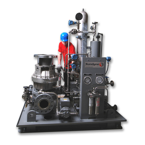
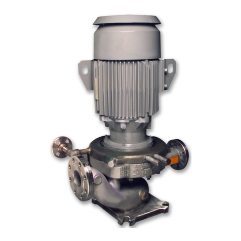
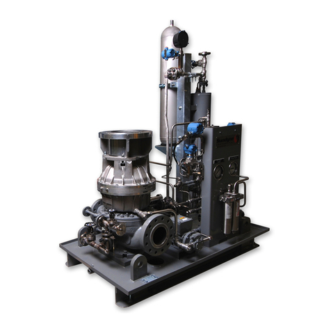
Sundyne LMV-802 Instruction manual

SA-07-11-37 Rev Orig Jan 2009
Installation, Operation
& Maintenance Manual
Sundyne Pumps
Model:
LMV-802
SA-07-11-37, Rev Orig.
Jan 2009

http://www.sundyne.com
Copyright
All rights reserved. No part of this publication may be reproduced, stored in a retrieval system or transmitted in any
form or by any means, electronic, mechanical, photocopying, recording or otherwise without the prior permission of
Sundyne Corporation.
© 2009 Sundyne Corporation
Warranty
Sundyne Corporation warrants to Buyer for a period of twelve (12) months from the date of being placed in service
(but not to exceed eighteen (18) months after the date of shipment) that the equipment at the time of shipment will
be free from defects of design, material and workmanship. If any defects or malperformance occur during the
warranty period, Sundyne’s sole obligation shall be limited to alteration, repair or replacement at Sundyne’s
expense, F.O.B. Factory, of parts or equipment, which upon return to Sundyne and upon Sundyne’s examination
prove to be defective. Equipment and accessories not manufactured by Sundyne are warranted only to the extent of
and by the original manufacturers’ warranty. Sundyne shall not be liable for damage or wear to equipment caused by
abnormal conditions, vibration, failure to properly prime or to operate equipment without flow or caused by
corrosives, abrasives or foreign objects. THE FOREGOING WARRANTY IS EXCLUSIVE AND IN LIEU OF
ALL OTHER WARRANTIES, WHETHER EXPRESSED OR IMPLIED INCLUDING ANY WARRANTY OF
MERCHANTABILITY OR FITNESS FOR ANY PARTICULAR PURPOSE. In no event shall Sundyne be liable
for consequential or incidental damages

SA-07-11-37 Rev Orig Jan 2009
i
Contents
CONTENTS ..........................................I
INTRODUCTION & SAFETY...............1
Sundyne Centrifugal Pumps............... 1
Text Symbols........................................... 1
Equipment and Safety Precautions .. 1
Wearing Personal Protective
Equipment............................................. 2
Using Forklifts....................................... 2
Ensuring Electrical Safety................... 2
Testing Equipment............................... 2
Using Chemicals................................... 2
Protection from Falling......................... 2
Preventative Machine Guards............ 3
EXPLOSION/FIRE HAZARD...3
Pre-Commission Checklist.................. 4
Familiarizing Yourself with the Pump 4
Driver Instructions................................ 4
Verifying Auxiliaries.............................. 4
Installing a Seal Environmental
Control System..................................... 4
Checking Driver Rotation.................... 4
Piping Connections.............................. 4
Start Up Checklist.................................. 5
Pressurizing the Fluid Loop................ 5
Servicing the Gearbox......................... 5
Auxiliary Lube Pump............................ 5
Setting the Valves................................ 5
Control Checklist ................................... 5
Process Conditions.............................. 5
Adjusting the Cooling Flow................. 5
Verifying Operating Conditions.......... 5
INSTALLATION...................................6
Inspection................................................. 6
Suction and Discharge Piping............ 6
Seal Environmental Control System. 7
START UP ...........................................8
Starting the LMV–802............................ 8
Controlling the Pump During Startup8
Single Operation................................... 8
Parallel Operation ................................ 8
NPSH - (Net Positive Suction Head
and Cavitation)........................................ 9
Recirculation........................................... 9
Prevention................................................ 9
Temperature Rise................................... 9
Suction and Discharge Gauges ......... 9
OPERATION & CONTROL................10
Operation of Sundyne Pumps.......... 10
Suction Conditions............................. 10
Minimum Flow Conditions................. 10
Entrained Gases................................. 10
System Head Curve........................... 10
Parallel Operation .............................. 11
MAINTENANCE.................................12
Disassembling the LMV-802.............. 12
Reassembling the LMV-802............... 17
TROUBLESHOOTING.......................25
Troubleshooting the Sundyne LMV-
802 PUMP............................................... 25
Pump Mechanical Seals..................... 27

SA-07-11-37 Rev Orig Jan 2009
ii
SPECIFICATIONS.............................29
Gearbox and Pump Torque Values..
..............................................................29-30
Pump Spare Parts List........................ 31
Inducer and Stud.................................. 32
Pump Exploded View.......................... 35
Single Seal Arrangement................... 36
Double Seal Arrangement.................. 37
Tandem Seal Arrangement................ 38
INDEX................................................39

Instruction and Operation Manual
SA-07-11-37 Rev Orig 1 Jan 2009
INTRODUCTION & SAFETY
Sundyne Centrifugal Pumps
Sundyne pumps provide high-energy
performance and competitive efficiencies in an
industrial quality, compact unit that is simple to
maintain. Sundyne pumps are single stage that
utilize an integral gearbox. Designed to to
increase the pressure of a continuous flow of
fluid by applying centrifugal action, Sundyne
pumps are most commonly used in HPI, CPI,
and Boiler Feed applications. Commonly applied
in refineries, petrochemical plants, and power
generation plants, Sundyne pumps are used in
high-head, low-to-medium flow processes.
This manual presents installation, servicing,
troubleshooting, maintenance and spare parts
information for the latest configuration of
Sundyne centrifugal pumps.
Note: Parenthetical numbers included in the
text correspond to item numbers on the
illustrated figures. The correct spare
part can be ordered for any generation
pump by referencing the item and serial
numbers.
Text Symbols
The following symbols may be found in the text
of this manual.
They have the following meanings:
WARNING: Text accompanied by this
symbol indicates that failure to follow
directions could result in bodily harm or
death.
ELECTRICAL HAZARD: Text
accompanied by this symbol indicates
that failure to follow directions could result
in electrical damage to equipment or
electrical shock.
RECOMMENDED: Text accompanied by
this symbol indicates recommended
usage.
REMINDER: Text accompanied by this
symbol indicates a reminder to perform
an action.
EQUIPMENT USE ALERT: Text
accompanied by this symbol indicates
that failure to follow directions could result
in damage to equipment.
Equipment and Safety Precautions
Sundyne Corporation manufactures centrifugal
pumps to exacting International Quality
Management System Standards (ISO 9001) as
certified and audited by Lloyd’s Register Quality
Assurance Limited. Genuine parts and
accessories are specifically designed and tested
for use with these products to ensure continued
product quality and performance. Sundyne
cannot test all parts and accessories sourced
from other vendors; incorrect design and/or
fabrication of such parts and accessories may
adversely affect the performance and safety
features of these products. Failure to properly
select, install or use authorized Sundyne pump
parts and accessories is considered misuse and
damage or failure caused by misuse is not

Instruction and Operation Manual
SA-07-11-37 Rev Orig 2 Jan 2009
covered by Sundyne’s warranty. Additionally,
modification of Sundyne products or removal of
original components may impair the safety of
these products and their effective operation.
CAUTION
Sundyne pumps may handle hazardous,
flammable, and/or toxic fluids. Proper personal
protective equipment should be worn.
Precautions must be taken to prevent physical
injury. Pumpage must be handled and disposed
of in accordance with applicable environmental
regulations.
Note: Safety procedures must be applied
prior to any installation, maintenance,
or repair of a Sundyne pump. Failure to
follow safety precautions may lead to
injury!
Wearing Personal Protective
Equipment
To ensure safety, protective equipment must be
worn at all times when installing, performing
maintenance, or repairing equipment. The
following safety recommendations must be
adhered to for optimum safety:
•Safety glasses, with the minimum
requirement of side shields, must be
worn at all times.
•Steel-toed shoes must be worn when
lifting equipment greater than 15 pounds
(7 kg) or if pallet jacks or forklifts are
operated.
•Hearing protection is strongly
recommended at all times when noise
levels exceed 85 dB during an eight
(8.0) hour period.
Note: Chemical resistant gloves must be used
if chemicals are utilized (refer to Using
Chemicals for additional information).
Note: A dust mask respirator must be worn if
chemicals have warning labels
regarding fumes, dust, or mists.
When using more than one piece of protective
equipment, consider their compatibility. For
example, safety glasses will not interfere with
hearing protection equipment. Be sure to clean
all pieces of personal protective equipment
immediately after each use.
Using Forklifts
Any persons operating a forklift must have an
active recognized operator license.
Note: Before initializing forklift operation,
verify that the lift is in a safe operating
position.
Ensuring Electrical Safety
All electrical sources must be powered-off
before installation, service, or repair of
equipment occurs.
Note: Sundyne recommends that a Lock-
out/Tag-out program be followed prior
to altering the equipment. Locks or
tags must be provided to warn
employees that equipment is
temporarily unavailable.
Once all work has been completed, the person
installing the lock or tag must remove it
according to company procedure.
Testing Equipment
Prior to performing a test on newly installed,
maintained, or repaired equipment; all personnel
in the immediate area must be warned.
Note: Follow company procedures prior to
equipment testing at all times.
Using Chemicals
Any chemicals to be used must be accompanied
by a relevant material safety data sheet (MSDS),
in accordance with government legislation. If
applicable, use chemical proof gloves.
Note: An eye wash station (or equivalent)
should be available in the event of
injury. If any hazardous or flammable
chemicals pass through the equipment,
a complete decontamination of the
equipment is required.
Protection from Falling
Fall protection and associated preventative
measures are required when working on
equipment located six feet or higher from the
ground.
Note: Follow company fall prevention
procedures prior to working on
equipment.

Instruction and Operation Manual
SA-07-11-37 Rev Orig 3 Jan 2009
Preventative Machine Guards
Preventative guards must remain in place on all
equipment.
Note: Only remove the guards while
performing maintenance or repair.
Replace the guards immediately after working
on the equipment and prior to start up.
EXPLOSION/FIRE HAZARD
Note: Never use an acetylene torch, open
flame, or heat to attempt to remove
parts that have seized together in
Sundyne equipment. Any residual
process gas or liquid that is flammable
can result in an explosion or fire with
potential for serious injury or death.

Instruction and Operation Manual
SA-07-11-37 Rev Orig 4 Jan 2009
Pre-Commission Checklist
Familiarizing Yourself with the Pump
Before servicing and starting up the Sundyne
pump, carefully review all information on the
product, including:
•Specification sheets
•Outline drawings
•Performance curves
•Instruction and related manuals.
•System P&ID/Process Flow Diagram
(Clients equipment).
•Control system and operational
philosophy/narrative (client).
Familiarize yourself with the pump configuration
before starting and operating the pump.
Driver Instructions
Carefully follow all installation and starting
instructions provided by the driver manufacturer.
This information is included in the final data
package.
Verifying Auxiliaries
Before start up, verify that the following
auxiliaries are met:
•Check the utility connections.
•Verify that the auxiliary piping conforms
to Sundyne standards, as indicated in
the detailed specifications.
•Verify all switch and instrument
connections
•Verify that all switch and instrument
settings are set to normal operating
standards.
•Calibrate all measurement equipment,
such as Flow meters, ampere meters,
and pressure meters,ect.
Installing a Seal Environmental Control
System
Install a system to control the seal environment.
Also, verify that port 1 is properly vented.
If required, install drain piping overhead to
ensure that the environment operates under
normal conditions. For more information,
contact Sundyne Corporation.
Checking Driver Rotation
Verify that the direction of the driver rotates in
the same direction as the arrow stamped or cast
on the pump casing.
*Un-coupled
Piping Connections
Verify that the following bolted or threaded
connections are tight:
Pump flange bolts
Seal environment piping and port
connections
Cooling water connections to heat
exchanger (if applicable)
Gearbox oil drain plug
Pump case drain plug

Instruction and Operation Manual
SA-07-11-37 Rev Orig 5 Jan 2009
Start Up Checklist
Pressurizing the Fluid Loop
Pressurize the double seal buffer loop or
external seal flush, if required, prior to admitting
fluid into the pump casing.
Servicing the Gearbox
Fill the gearbox with lube oil up to a quarter inch
(¼) or 6 mm from the top of the oil level sight
glass.
Note: Prior to using lube oil, verify that it
conforms to acceptable lube oil
specification standards. Refer to the
SPECIFICATIONS section in this
manual for more information.
Under normal operation, the lube oil level will
lower about a quarter inch than when idle.
Additionally bubbles will appear at the top of the
sight glass.
Note: Sundyne recommends that gearbox lube
oil be changed at least every six
months.
For requirement information about priming the
lube oil system, refer to Starting the Pump in this
manual.
Auxiliary Lube Pump
If your pump includes an auxiliary lubrication
pump, unlock the electrical circuit and move it to
the “hand” position. Check for oil leaks and
recheck the oil level.
Setting the Valves
To set the pump to the designated operating
point, start the pump with the suction valve in
the open position while throttling the discharge
valve.
Control Checklist
Process Conditions
Verify the following process conditions against
the specifications in this manual:
•Process conditions
•Suction pressure
•Suction temperature
•Discharge pressure
Check with your Sundyne representative if the
operation conditions of your pump must run
under different parameters than indicated by the
specifications in this manual.
Adjusting the Cooling Flow
If your model pump includes an installed heat
exchanger for the gearbox, adjust the cooling
flow to keep the temperature of the gearbox
sump at 140°-180°F (60°-82°C).
Verifying Operating Conditions
Verify the following parameters against the
specifications included in this manual:
•Total head
•Flow rate
•Power consumption
•Specific gravity
•Viscosity
•Net Positive Suction Head (NPSH)
The status of these conditions will significantly
alter performance of the pump if they are not in
accordance with the specification sheet.

Instruction and Operation Manual
SA-07-11-37 Rev Orig 6 Jan 2009
INSTALLATION
Inspection
Immediately inspect your Sundyne product upon
receipt of the equipment. Check for any
damage, which may have occurred during
shipment. Notify the carrier and Sundyne
immediately if damage is evident.
Note: The input shaft on the pump may not
turn freely due to seal drag and speed
increasing gear meshes. If the input
shaft does turn freely, and if rotation is
“not smooth,” damage may have
occurred during shipping.
Suction and Discharge Piping
Please adhere to the following best practices for
installing and maintaining suction and discharge
piping:
Install a suction strainer (12 mesh - .062" or
1.6mm opening) and clean the suction line
prior to starting the pump. This procedure
will protect the impeller from damage by mill
scale, welding slag, or other foreign particles
during initial startup.
Note: Sundyne Recommends installation of a
differential pressure instrument across
strainer to indicate strainer condition.
When installing piping to the pump, ensure that
all piping is supported independently from
the pump.
All piping must always line up with the pump
flanges.
Note: Never use force to position piping into
place at the flanged suction and
discharge connection locations. Failure
to do so may impose excessive strains
on the unit.
Avoid using elbow fittings near the suction
flange. When necessary, use long radius
elbow fittings. Sundyne recommends using
a straight pipe assembly of at least three
times the length of the pipe diameter
between an elbow and suction flange.
Note: Carefully select the size of pipe and
fittings to be installed so that friction
losses will remain low.
Never use a suction pipe that is smaller in
diameter than the pump suction inlet.
Sundyne recommends installation of a discharge
check valve to prevent reverse rotation.
Use block valves (both suction and discharge)
when isolating the pump during shutdown.
This practice will minimize process leakage
and prevent possible reverse rotation from
pump back-flow.

Instruction and Operation Manual
SA-07-11-37 Rev Orig 7 Jan 2009
Seal Environmental Control System
A seal environmental control system may be
required depending upon the pump seal
arrangement and application.
Always maintain the pump seal environment as
detailed on the specification sheet that
accompanies each unit.
Note: For most applications, a standard
control system can be obtained from
the factory.
Ensure that the specified seal environmental
control system is properly installed and that the
ports are open (or plugged) as indicated in
Figure 1 below.
Note: Port 1 must always be open so that it is
free to drain.
Figure 1 Seal Housing Port Identification

Instruction and Operation Manual
SA-07-11-37 Rev Orig 8 Jan 2009
START UP
Starting the LMV–802
To start the pump perform the following tasks:
•Check to ensure that the driver has
been serviced in accordance with the
instructions provided by the driver
manufacturer.
•Open the suction valve completely;
open the discharge valve about half
way.
•Check to ensure correct shaft rotation.
Rotation of the driver must be in the
same direction as the arrow on the
pump casing.
•Start the driver. Adjust the discharge
control valve to the desired flow and
check head and horsepower against
requirements on the pump specification
sheet.
Note: A buffer fluid or external seal flush
auxiliary system is required, this system
should be pressurized prior to admitting
process fluid into the pump. If port 6 is
not used for a seal flush, it is
recommended that a hand bleed valve
be installed at this location. Bleed air
and vapor before starting.
Controlling the Pump During Startup
To ensure control of the pump during start up,
follow the start up procedures for your desired
configuration.
Single Operation
Start the pump with the suction valve open while
throttling the discharge valve. This will
ensure that the pump will reach the design
flow operating point.
If the process fluid is near its vapor press, open
the supply vessel seal cavity vent so that the
pump is filled with liquid.
Parallel Operation
To prevent back-flow, place the check valves in
the discharge piping of each pump.
Note: Sundyne recommends installing
separate bypass loops around each
pump for additional operational
flexibility.
1. Start the first unit as described in the
Single Operation instructions.
2. Start the second unit with the bypass
valve set to maintain the flow above
minimum flow.
3. Open the discharge valve on the second
unit so that the design flow of both units
is maintained.
Note: Do not operate the pumps at their peak
head capability.
Sundyne recommends that separate flow
controls be used on each pump to provide a
lower minimum flow range than is achieved by
pressure control.

Instruction and Operation Manual
SA-07-11-37 Rev Orig 9 Jan 2009
NPSH - (Net Positive Suction Head and Cavitation)
In order to protect the pump, it is recommended
that NPSH available be at least two-feet greater
than NPSH required. If the pump is operated
beyond the design capacity the increase in
required NPSH with the increase in capacity will
eventually result in cavitation. This is usually
identifiable as a loud rumble, sometimes
described as sounding like gravel is being
pumped. Continuous operation in a state of
cavitation may cause serious damage to the
impeller. Vibration can result in more extensive
damage to the pump.
Recirculation
Centrifugal pumps can experience vibrations
from internal flow separations and recirculation
at low flow conditions. The operator must be
aware of the minimum flow recommendations of
the manufacturer. It is possible for a pump to
operate with some cavitation noise due to
recirculation without harm to the pump.
However, excessive noise and vibration are
signs that the pump may be subject to damage if
operation is continuous. Noise and vibration may
be accentuated by resonance in the discharge
line. This is especially true when a control valve
is located well downstream from the pump.
Prevention
It is essential that the pump be selected to mate
properly with the system head curve to prevent
the pump from operating on its curve where
damage may be sustained from recirculation or
cavitation. It is also essential that once it is
selected that it is properly controlled. Use of flow
control should be used in place of pressure
control if variable flows are to be experienced.
Pressure control is a very difficult and exacting
practice due to the relatively flat head capacity
curve of Sundyne pumps. Flow control, on the
other hand, can be quite precise and effective
.
Temperature Rise
Temperature rise within the pump is unlikely to
become of problem as long as the pump is not
operated below minimum flow
recommendations. If operation at low flows does
become mandatory or if the system causes the
pump discharge line to be blocked for any period
of time, a means of maintaining minimum flow
must be provided. Using either a continuous
bypass or a flow-controlled bypass can
accomplish this. The operator can calculate the
amount of bypass necessary to prevent boiling
liquid in the pump case and at the seal faces.
Please refer to the manufacturer for information
if this becomes necessary.
Suction and Discharge Gauges
It is recommended that suction and discharge
pressure gages be installed on any pump that is
not flow controlled. If no flow-measuring device
is installed there is not a way to determine
accurately where on its curve the pump is
operating.

Instruction and Operation Manual
SA-07-11-37 Rev Orig 10 Jan 2009
OPERATION & CONTROL
Operation of Sundyne Pumps
Under normal operation, several factors must be
taken into consideration to ensure successful
pump operation. Experienced pump operators
will be aware of jeopardizing factors and their
effects.
Suction Conditions
Improper flow of liquid into the impeller is the
most common operational abuse of centrifugal
pumps. Two conditions must exist to prevent
turbulence at the eye of the impeller.
See suction piping section.
Liquid reaching the impeller eye must
have enough vapor pressure to prevent
the fluid from flashing to a gas in the
impeller. If this condition occurs, it will
cause cavitation, which can damage the
impeller and inducer. When centrifugal
pumps cavitate the noise sounds like
the pump is “pumping gravel”. In high
speed, single stage pumps, this sound
may not be discernable. Cavitation can
be prevented by maintaining suction
pressure at a high enough level and
suction temperatures low enough to
maintain Net Positive Suction Head
(NPSH) available greater than Net
Positive Suction Head (NPSH) required
by the pumps.
Minimum Flow Conditions
Vibration and noise will occur during operation of
centrifugal pumps if either of two conditions
exist:
•Internal flow separations
•Recirculation at low flow conditions.
If the operator is noticing excessive noise or
vibration, operation must be suspended until the
cause is determined and corrected. Continued
use may cause damage to the pump.
Resonance in the discharge line can accentuate
noise, vibration, and damage to the pump,
primarily when a control valve is located an
excessive distance downstream from the pump.
Entrained Gases
The head and capacity of centrifugal pumps will
be reduced by gas that is drawn in with the
liquid. Under normal operating conditions,
centrifugal pumps can tolerate up to 2% of gas
(by volume). Entrained gases can cause
damage to mechanical seals with the exception
of double seals. If you have entrained gas,
contact Sundyne for further instruction.
System Head Curve
The point of intersection between the system
curve and the pump characteristic curve
determines the flow or operation for the
centrifugal pump. For steady flow to occur, the
system curve must intersect the pump
characteristic curve at a significant angle. The
following diagram gives examples of satisfactory
and unsatisfactory angles of intersection.
Figure 2. Typical Operation
Note: The curve for pump A has a significant
angle of intersection with system curves
D and E. The system curve D could
represent a system with the control
valve wide open while system E could
represent the same system but with the
throttle valve closed to reduce flow from
flow 1 to flow 2. Pump curve B, on the
other hand, will provide only flow 2,
even with the control valve wide open
(curve D). When the control valve is
partially closed to create system curve
E, the curve E and lower pump curve B
are practically parallel. The lack of a
significant angle of intersection means

Instruction and Operation Manual
SA-07-11-37 Rev Orig 11 Jan 2009
that the pump flow is likely to drift
aimlessly and not respond to control
valve position.
Parallel Operation
Maximizing control is critical when operating
centrifugal pumps in parallel. One pump can
overpower the other in regards to head at a
lower total flow. If a simple, unrestricted manifold
connects two pumps at the discharge head, the
discharge head of one pump is imposed on the
other. All pumps will see the same discharge
head at a given time. This is demonstrated on
the following curves:
The characteristic curves of two pumps
designated A and B are demonstrated in the
Parallel Operation figure.
Since no two pumps will have exactly the same
performance, it is assumed that pump A
produces a slight amount more head than pump
B. The pumps are arranged with a common
manifold as shown in Parallel Units Common
Valve figure.
Figure 3. Parallel Operation
Figure 4. Parallel Units Common Valve
The pressure in the manifold is set at P1; the
flow through pump A indicated as A1on the
preceding curve. At the same time, the flow
through pump B is indicated as B1. However, if
the throttle valve is closed to cause the manifold
pressure P to rise to P2, then flows through
pump A and B are A2and B2respectively. If the
throttle valve were closed even further, then
pump B would cease to flow entirely. Since
pump B would effectively be deadheaded, the
fluid in it would heat up and boil. During internal
boiling, it could encounter liquid slugging and
probable damage to the pump. Proper selection
of a control system can prevent this situation.

Instruction and Operation Manual
SA-07-11-37 Rev Orig 12 Jan 2009
MAINTENANCE
Disassembling the LMV-802
The following procedures apply to all
configurations of the LMV-802 process pump.
Refer to he specification sheet to determine your
specific pump configuration and optional
equipment included. Disassembly should be
done only to the extent necessary for repair.
Parenthetical numbers in the text correspond to
item numbers in the parts list section.
Note: The following replacement parts will be
required as a result of pump
disassembly and seal housing removal:
PART ITEM NO. QTY.
Impeller Tab washer 5 1
O-Ring Repair Kit -- 1
Thermal Barrier Gasket 87A 1
STEP 1
Remove nuts (914A) from the pump casing
studs.
STEP 2
Remove the driver and seal housing from the
pump casing (1).
Note: Exercise care not to damage the inducer
(9) if one is installed.
Note: Use hoist and hooks to prevent personal
injury.

Instruction and Operation Manual
SA-07-11-37 Rev Orig 13 Jan 2009
STEP 3
Prevent Impeller from moving using a strap
or chain wrench, loosen the inducer or
impeller nut.
Note: Left hand thread.
STEP 3 continued
Remove the inducer (9).
STEP 4
Pry the impeller (2) from the drive
shaft.
Note: The impeller is dynamically balancedand
should be replaced if it shows any sign
of damage.
STEP 5
Remove the impeller key (4).

Instruction and Operation Manual
SA-07-11-37 Rev Orig 14 Jan 2009
STEP 6
Mark the position of the seal housing to the
driver. These marks will ensure the seal
housing will be in the correct position when
reassembled.
STEP 7
Remove the seal rotating face (51A).
STEP 8
Remove seal housing (30) from the driver by
removing hex head bolts.
STEP 9
Remove seal housing gasket (87A).
STEP 10
Remove lower mechanical seal mating ring.

Instruction and Operation Manual
SA-07-11-37 Rev Orig 15 Jan 2009
STEP 11
Turn the seal housing over and remove the
three hex head cap screws.
STEP 12
Remove the throttle bushing (21B) and the
throttle bushing “O” ring (936H).
STEP 13
Remove seal retainer spacer (19A).
STEP 14
Remove lower mechanical seal (60A) and the
front and back mechanical seal “O” rings.

Instruction and Operation Manual
SA-07-11-37 Rev Orig 16 Jan 2009
STEP 15
Remove the seal spacer from the lower
mechanical seal.
Note: STEPS 12-15 will vary depending on the
seal arrangement on your pump. The
following procedures are for all seal
arrangements.
SINGLE SEAL
Remove the throttle bushing (21B), seal
retaining spacer (19A), mechanical seal (60A),
and seal spacer (52).
DOUBLE SEAL
Remove the upper mechanical seal (60B), seal
retaining spacer (19A), seal rotating face (51C),
seal spacer (52), and lower mechanical seal
(60A).
TANDEM SEAL
Remove the upper mechanical seal (60B), seal
retaining spacer (19A), seal rotating face (51B),
lower mechanical seal (60A), seal spacer (60A)
and lower shaft sleeve.
Table of contents
Other Sundyne Water Pump manuals
Popular Water Pump manuals by other brands

FLOJET
FLOJET G-57 Series Installation & operation instructions

Armstrong
Armstrong Design Envelope 4300 Quick installation guide

Liberty Pumps
Liberty Pumps 2LE Series installation manual

Graco
Graco Mark V International Instructions and parts list

Varian
Varian HS-16 instruction manual

Tecnogas
Tecnogas Nuvola Operation manual