Installation and Operation Manual
SA-07-11-87 Rev A 3 January 2019
Equipment and Safety Precautions
Sundyne LLC manufactures centrifugal pumps
to exacting International Quality Management
System Standards (ISO 9001) as certified and
audited by Lloyd’s Register Quality Assurance
Limited. Genuine parts and accessories are
specifically designed and tested for use with
these products to ensure continued product
quality and performance. Sundyne cannot test
all parts and accessories sourced from other
vendors; incorrect design and/or fabrication of
such parts and accessories may adversely affect
the performance and safety features of these
products. Failure to properly select, install or use
authorized Sundyne pump parts and
accessories is considered misuse and damage
or failure caused by misuse is not covered by
Sundyne’s warranty. Additionally, modification
of Sundyne products or removal of original
components may impair the safety of these
products and their effective operation.
CHEMICAL HAZARD
Sundyne pumps may handle hazardous,
flammable, and/or toxic fluids. Proper personal
protective equipment should be worn.
Precautions must be taken to prevent physical
injury and compliance must be ensured with
COSHH, EPA or any applicable Health and
Safety legislation. Pumpage must be handled
and disposed of in accordance with applicable
environmental regulations.
Safety procedures must be applied
prior to any installation, maintenance,
or repair of a Sundyne pump. Failure to
follow safety precautions may lead to
injury!
All pumps returned to Sundyne or HMD
for servicing must have a
decontamination certificate and the
appropriate Health and Safety data
sheets.
Wearing Personal Protective Equipment
To ensure safety, protective equipment must be
worn at all times when installing, performing
maintenance, or repairing equipment. The
following safety recommendations must be
adhered to for optimum safety:
•Safety glasses with side shields that meet
ANSI Z87.1 standard for impact
resistance must be worn at all times.
•Protective footwear (steel-toe shoes)
meeting ASTM F2413-11 standard
specification for performance
requirement of protective footwear.
•Hearing protection is strongly
recommended at all times when noise
levels exceed 85 dB during an eight
(8.0) hour period.
Chemical resistant gloves must be used
if chemicals are utilized (refer to Using
Chemicals for additional information).
A dust mask respirator must be worn if
chemicals have warning labels
regarding fumes, dust, or mists.
When using more than one piece of protective
equipment, consider their compatibility. For
example, safety glasses will not interfere with
hearing protection equipment. Be sure to clean
all pieces of personal protective equipment
immediately after each use.
Refer to Section 8 of the chemical specific
Safety Data Sheet for any additional PPE
requirements.
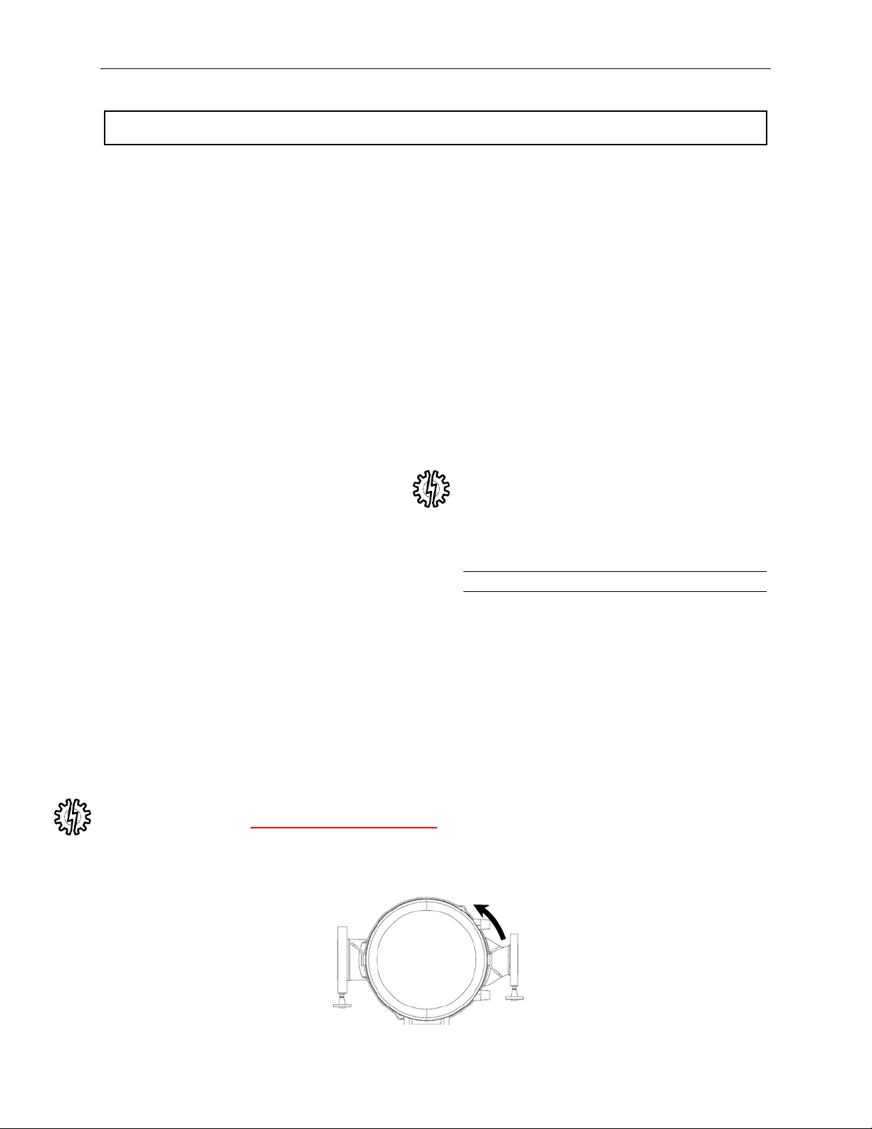
Lifting
Attention must be given to the safe handling of all
items. This applies to both installation and
maintenance. Where pumps, pump units, or
components weigh in excess of 35 lbs (16Kg) it is
recommended that suitable lifting equipment
should be used in the correct manner to ensure
that personal injury or damage to pump
components does not occur. Note that lifting
eyes fitted to individual pieces such as pump and
motor are designed to lift only this part and not
the complete assembly
Using Forklifts
Any persons operating a forklift must have an
active recognized operator license.