Sunerg Solar Energy Calor Top 300D Operating instructions

Calor Top 300D(S)
Air-source Heat Pump Water Heater
INSTALLATION & OWNER’S MANUAL
Applicable Models:
:CALOR TOP 300D
CALOR TOP 300D(S)
v. 13.04

2
Content
1.
General Information............................................................................4
1.1
Measurements..................................................................................................................................
4
1.2
External appearance..................................................................................................................
4
1.3
Nomenclature.........................................................................................................................
4
2.
Combo Type Heat Pump Water Heater....................................................5
2.1
Features.......................................................................................................................
5
2.2
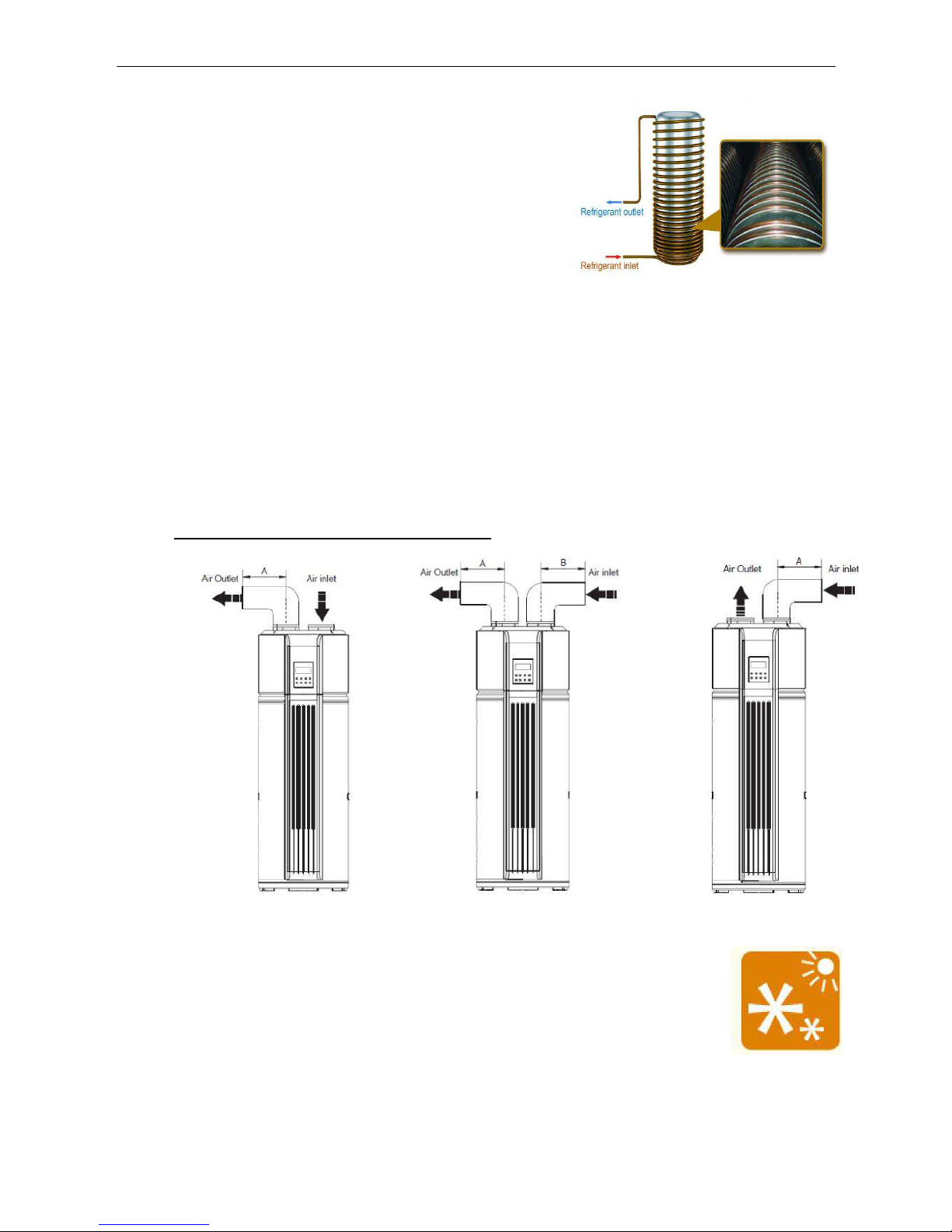
Refrigerant circuit ....................................................................................................................
6
2.3
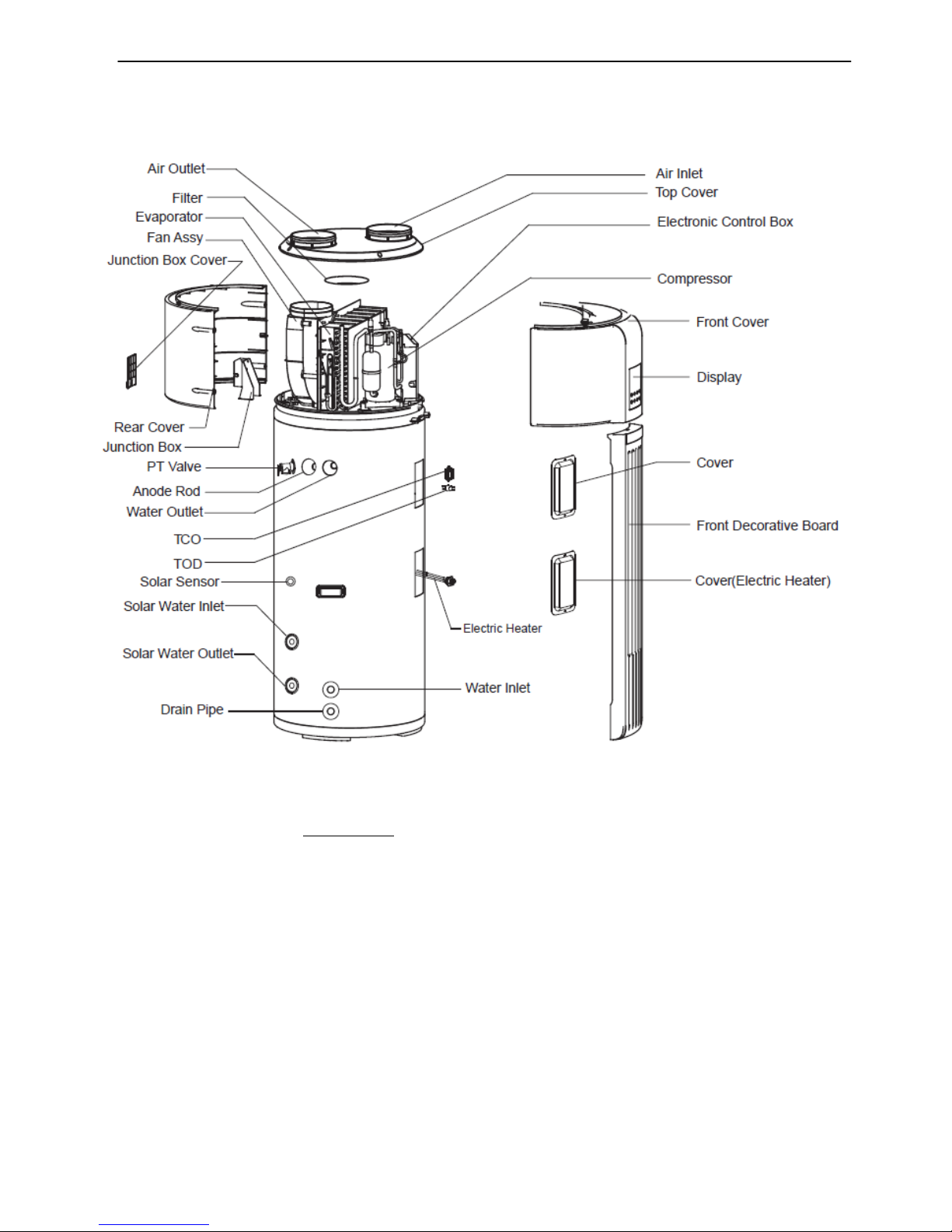
Unit structure...............................................................................................................................
7
2.4
Specifications..............................................................................................................................
8
2.5
Dimension
.................................................................................................................................11
2.6
Performance diagram........................................................................................................
12
2.7
Wiring diagram..........................................................................................................
13
2.8
Installation ...............................................................................................................................
14
2.9
Water affusion and effusion...................................................................................................
22
2.10
Trial run .........................................................................................................................................
23
2.11
Maintenance..................................................................................................................................
24
2.12
Trouble shooting.....................................................................................................................
25
2.13
Function ........................................................................................................................
29
2.14
Frequently Asked Questions............................................................................................
30
2.15
Operation............................................................................................................................
38
2.16
Accessories...................................................................................................................................
32
2.17
Exploded view
....................................................................................................................39
2.18
Typical applications in cooling and purification of air
..........................................................41
2.19
Running logic
......................................................................................................................44

3

4
1. General Information
1.1 Measurements
1.2 External appearance
1.3 Nomenclature
Model Label
Dimension
(mm, D×H) Net/Gross weight (kg) Power Supply
Calor Top 300D RSJ-35/300RDN3-D
Ф650×1920
117/144
220~240V-mono-50Hz
Calor Top 300D(S) RSJ-35/300RDN3-D(S)
Ф650×1920
123/144
220~240V-mono-50Hz
Heat Pump Water Heater model

5
2.
Combo Type Heat Pump Water Heater
2.1 Features
Safety
:
1. Complete isolation between water and electricity
without electric shock problem, more safety.
2. No fuel tubes and storage, no potential danger from oil
leakage, fire, explosion, and so on.
3. No cross contamination potential, the condenser coil is
wrapped around the stainlessinner tank (MAX protection for
corrosion)
Minimal leakage: With 15°C of ambient temperature and 43°C of average temperature in tank, the
inner tank temperature decrease only of 1,8°C.
Quikly running operation: The unit reaches running operation, with cold start, in 203 minutes
( inlet water temperature: 15°C, outlet water temperature: 45°C, ambient
temperature: 15°C).
Maximum outlet
water temperature:
60
°C
.
Flexible installation achieves by
long air inlet / outlet
duct enables ducted length up to 10 meters.
NOTE:
AIR INLET IS ON THE RIGHT SIDE OF THE UNIT!
(IN CALOR TOP 200D MODEL IS ON LEFT SIDE)
Note:
A ≤10m or A+B ≤10m
A
utomatic startup and shutdown, automatic defrosting by revising refrigerantcycle to
save the extra operation.
According to the heat pump principle, the unit absorbs heat from outdoor air and
produce heat water thermal efficiency can be approximately
3.6
(Under the
condition A15/12
W15/45 ;
A= external air temperature W= outlet hot water temperature
).
Within the temperature range from
-20 and 43
°C the unit will not be affected by night,cloudy
sky,rainevensnow weather.

6
Operation Mode
There are 2 operation mode in this unit:
•
ECONOMY MODE
: Water outlet is heated by compressor of Heat Pump; If the target setting
water is higher than max. temp (heat pump), the unit will activate heat pump firstly to max temp,
then stop heat pump and activate E-heater to continually heat water to the target temperature.
•
E-HEATER MODE
: Water outlet is heated only by E-heater.
2.2 Refrigerant circuit (example: Calor Top 300D(S) )
Compressor:
RB233GRDC, R134a compressor, supplied by Mitsubishi.
Evaporator:
copper tube and aluminum fin type heat exchanger.
EEV: “
Electronic Expansion Valve”, the opening is regulated according to the discharge air
temperature of compressor.
Fan:
centrifugal fan with three speeds. The motor is supplied by Welling.
ATCO:
If the water temperature is higher than 78°C, the ATCO will automatically shut off the power of
thecompressor and E-heater, and turn iton if the temperature falls down below 68°C
.
TCO
If the water temperature is higher than 85°C, the TCO will automatically shut offthe power of the
compressor and E-heater, it should be re-turnmanually
High Pressure Switch:
When the discharge pressure of compressor is 2.76Mpa (27.5atm) or
higher, the protection switch will be triggered, and if the discharge pressure is down to 2.07MPa
(20atm), the protection switch will be recovered.
T5U
Condensator
(External wiring)
EEV
One-way valve
Electronic Expansion Valve
4-way valve
High pressure switch
Compressor
Evaporator
Dryer
E-heater
Water inlet
Solar
water inlet
Solar
water outlet
Water outlet

7
2.3 Unit structure
Note:
1.
Calor Top 300D doesn’t have solar energy coil inside.
2.
When ordering repair parts please always give the following information:
- Model, serial and product number.
- Parts name.
3.
This unit is recommended for hot water centralized plants in multifamily
buildings, shops, restaurant, hair saloon, etc. The unit can be used in other
way, like prewarming water of heating system to realize a great energy
saving. It’s possible to integrate the unit with solar collectors (only CalorTop
300 D(S) model).

8
2.4 Specifications
Model Calor Top 300D
Heat source Heat pump E-heater
Running ambient temperature
℃
-7~43 -20
~
43
Output water temperature
℃
Default 55
℃
,38
℃
~60
℃
Power supply Ph, V, Hz 1, 220-240~, 50
Storage size Ltr 300
Water heating
Capacity W 1500 3000
C.O.P. 3.6 1
Max. current A 6.5 13.0
Unit
Dimension (D×H) mm Ф650 × 1920
Packing (W×H×D) mm 750 × 2150 × 780
Net/gross weight kg 117 / 144
Sound pressure / sound power level dB(A) 48 / 60
Refrigerant type/quantity kg R134a/1.2
Refrigerant design pressure MPa (atm)
3.0 / 1.2 (30 / 12)
Throttling type
Electric expansion valve
System protection
TCO, ATCO, PT valve, automatic defrosting, over-load
protector, high-pressure protector, etc..
Air flow m
3
/h 414 / 355 / 312
Compressor
Model
RB233GRDC
Type
Rotary
Brand
Mitsubishi
Capacity Btu/h 9502 / 11447
Input W 895 / 1095
Rated current(RLA) A 4.1 / 5.0
Locked rotor Amp(LRA) A 30
Thermal protector
UP3QE0594-T56 (Internal)
Capacitor
30µF / 440-450V
Refrigerant oil ml 440
Evaporator coil
Number of rows
3
Tube pitch(a)x row pitch(b) mm 22×19.05
Fin spacing mm 1.6
Fin type (code)
Hydrophilic aluminum
Tube outside dia. and type mm φ7.94 Inner groove copper tube
Coil length x height mm 482×352
Number of circuits
4
Fan motor
Model
YDK30-6R
Brand
Welling
Input W 68/56/50
Speed giri/min 620/530/465

9
Locked rotor Amp(LRA) A 0.35
Capacitor
2.5µF/450V
Water pipeline
Water inlet pipe
DN20
Water outlet pipe
DN20
Drainage pipe
DN20
PT valve joint
DN20
Max. operating pressure MPa (atm)
1.0 (10)
Heat exchanger Dividing wall type heat exchanger
E-heater W 3000×1
Hot water yield m
3
/h 0.043 0.086
Loading Quantity 20'/40'/40H Pcs 21/45/45
Model Calor Top 300D(S)
Heat source Heat pump E-heater
Running ambient temperature
℃
-7
~
43 -20
~
43
Output water temperature
℃
Default 55
℃
,38
℃
~
60
℃
Power supply Ph, V, Hz 1, 220-240~, 50
Storage size Ltr 300
Water heating
Capacity W 3000 3000
COP kW/kW 3.6 1
Max. current A 6.5 13.0
Unit
Dimension (D×H) mm
Ф650 × 1920
Packing (W×H×D) mm 750 × 2150 × 780
Net/gross weight kg 123 / 144
Sound pressure / sound power level dB(A) 48 / 60
Refrigerant type/quantity kg R134a /1.2
Refrigerant design pressure MPa (atm)
3.0 / 1.2 (30 / 12)
Throttling type
Electric expansion valve
System protection
TCO, ATCO, PT valve, automatic defrosting, over-load
protector, high-pressure protector, etc..
Air flow m
3
/h 414 / 355 / 312
Compressor
Model
RB233GRDC
Type
Rotary
Brand
Mitsubishi
Capacity Btu/h 9502 / 11447

10
Input W 895 / 1095
Rated current (RLA) A 4.1 / 5.0
Locked rotor Amp (LRA) A 30
Thermal protector
UP3QE0594-T56 (Internal)
Capacitor
30µF / 440
-450V
Refrigerant oil ml 440
Evaporator coil
Number of rows
3
Tube pitch(a)x row pitch(b)
mm 22×19.05
Fin spacing mm 1.6
Fin type (code)
Hydrophilic aluminum
Tube outside dia. and type mm
φ7.94 Inner groove copper tube
Coil length x height mm 482×352
Number of circuits
4
Fan motor
Model
YDK30-6R
Brand
Welling
Input W 68 / 56 / 50
Speed r/min 620/530/465
Locked rotor Amp(LRA) A 0.35
Capacitor
2.5µF / 450V
Water pipeline
Water inlet pipe
DN20
Water outlet pipe
DN20
Drainage pipe
DN20
PT valve joint
DN20
Max. operating pressure MPa (atm)
1.0 (10)
Heat exchanger Dividing wall type heat exchanger
Solar heat exchanger
Water inlet pipe
DN20
Water outlet pipe
DN20
Heat exchanger
Stainless steel SUS316L
Dim.×Length mm 22 × 10000
Max. operating pressure MPa (atm)
0.7 (7)
E-heater W 3000 × 1
Hot water yield m
3
/h 0.086
Loading Quantity 20'/40'/40H Pcs 21/45/45
Notes:
1. The test conditions: outdoor temperature 15/12℃(DB/WB), inlet water temperature 15℃, outlet water
temperature 45℃.
2. Sound pressure value test conditions: four side of the unit, distance is 1m, and height is 1m + half of the unit’s
height. The sound pressure level is following this procedure:
3. The specification may be changed for product improvement, please refer to the nameplate.

11
2.5 Dimensions (Unit: mm)
Installing the equipment in any of the following places may lead to malfunction of equipment (if it is
inevitable, consult the supplier).
•The site contains mineral oils such as cutting lubricant.
•Seaside where the air contains much salt.
•Hot spring area where corrosive gases exist, e.g., sulfide gas.
•Factories where the power voltage fluctuates seriously.
•Inside a car or cabin.
•Place like kitchen where oil permeates.
•Place where strong electromagnetic waves exist.
•Place where flammable gases or materials exist.
•Place where acid or alkali gases evaporate.
•Other special environments.
Precautions before installation
•Decide the correct way of conveying the equipment.
•If the unit has to be installed on a metal part of the building, electric insulation must be installed,
and the installation must meet the relevant technical standards for electric devices.

12
2.6 Performance diagram
The unit has two heat sources:Heat pump and E-heater. Heat source will be automatically selected
by unit. But manually E-Heater operation is available.
Operation range
Setting water temperature target range: 38~60°C.
Heat pump running ambient temperature range: -7~43°C.
E-heater running ambient temperature range: -20~43°C.
Water temperature limits
Unit: °C
Ambient temperature (T4) T4
≤
-7 -7
≤
T4<-2 -2
≤
T4<2 2
≤
T4<7 2
≤
T4<7 43
≤
T4
Max. temperature (Heat pump)
- 42 47 55 60 -
Max. temperature (E-heater) 60 60 60 60 60 60
Capacity & COP

13
2.7 Wiring diagram

14
2.8 Installation
Transport
In order to avoid scratch or deformation of the unit surface, apply guard boards to the contacting
surface. No contact of fingers and other things with the vanes. Don’t incline the unit more than 15
°
in
moving, and keep it vertical when installing.
The unit is so heavy that it should be carried by two or more persons. Otherwise, it might cause
injury and damage.
Location of installation
Enough space for installation and maintenance shall be preserved.
The air inlet and outlet should be free from obstacles and strong wind.
The base surface should be flat, which should be inclined no more than 2°, and able to bear the
weight of the unit and suitable for installing the unit without increasing noise or vibration.
The operation noise and air flow expelled should not affect neighbors.
No flammable gas is leaked nearby.
It is convenient for piping and wiring.
If the unit has to be installed in the indoor space, the unit might cause indoor temperature decreased
and noise, please take preventive measures for this.
If the unit has to be installed on a metal part of building, make sure the well electric insulation
which should meet the relevant local electric standard.
Maintenance space requirements
Before installing the unit, reserve the space of maintenance shown in the following figure.

15
Water system piping
In case of installing the unit at a place where outside temperature below freezing point,
insulation must be provided for all hydraulic components.
Water inlet or outlet pipes: The specification of the water inlet or outlet thread is RC3/4", which
is external thread. Pipes should be heat-insulated well.
Installation of the pipe for PT valve: The specification of the valve connecting thread is RC3/4",
which is external thread. After installation, it must be confirmed that the drainpipe outlet is exposed
in the air.
Installation of the one way valve: The specification of the valve thread in accessories is RC3/4".
It is used to prevent water from flowing backwards.
The drainage pipe should be insulated to prevent water inside pipe from freezing in cold weather.
After water system piping connection, turn on the inlet and outlet valve to effuse the tank. When
water flow smoothly out from outlet pipe, the tank is full, turn off all valves to check the pipeline
leakage.
If the inlet water pressure is less than 0.15MPa (1,5atm), a pump should be installed at the water
inlet. If the water supply hydraulic is higher than 0.65MPa (6,5atm), a reducing valve should be
installed at the water inlet pipe.
Condensate may be leaked from unit if
drainage pipe is blocked, so a drainage
pan should be installed as instruction below.
(Only 300D(S) )

16
ATTENTION! Do not dismantle the PT Valve or block off the Drainage pipe, It will cause
explosion and injury.
To smoothly drain condensate, the unit should be installed at a horizontal floor. Otherwise, the
drain vent is ensured at the lowest place, and recommending the inclination angle of unit to the
ground should be no more than 2°.
Air duct connection
A B C
A
Air inlet and outlet with duct A+B
≤
10m
B
Only air outlet with duct A
≤
10m Recommended
for
summer
that could
charge fresh air into room.
C
Only air inlet with duct A
≤
10m Recommended
for
winter
where there
is other heat source in the room.

17
The resistance of duct will decrease air-flow-rate, which will lead to capacity of unit decreased.
Forthecaseofunitwith canvas,oftheduct total lengthshouldbenomorethan 10morthe maximum
static pressureshould within25Pa,and the quantity bending should be no more than 3.
For unit air outlet with duct, when unit operating, condensate will be generated around outside of duct,
please pay attention to the drainage work, we suggest to wrap the thermal insulated layer around outside
if the duct.
For unit air outlet with duct, when unit operating, condensate will be generated around outside of duct,
please pay attention to the drainage work, we suggest to wrap the thermal insulated layer around outside
if the duct.
In terms of the main unit connect with canvas reaching to outdoor, a reliable water-resistant
measure must be conduct on the duct, resist water drop into internal of the main unit.
Filter should be installed at the unit inlet, if the air inlet is not connected with duct. In terms
of the unit with duct, filter should be put on the position of duct inlet.
Duct description Round duct Rectangle duct Other shaped duct
Dimension (mm)
Ф190
190×190
Refer to above data
Straight-line pressure drop (Pa/m)
≤
2
≤
2
Straight-line length (m)
≤
10
≤
10
Bent pressure drop (Pa)
≤
2
≤
2
Bent’s quantity
≤
5
≤
5
Canvas Duct description

18
Electric connection
The power supply should be an independent circuit with rated voltage.
Power supply circuit should be earthed effectively. The wiring must be performed by professional
technicians in accordance with national wiring regulations and the circuit diagram.
An all-pole disconnection device which has at least 3mm separation distance in all pole and a
residual current device (RCD) with the rating of above 10mA shall be incorporated in the fixed wiring
according to the national rule.
Set the electric leakage protector according to the relevant electric technical standards of thelocal.
The power cord and the signal cord shall be laid out neatly and properly without mutual interference
or contacting the connection pipe or valve.
After wire connection, check it again and make sure the correctness before power on.
Specifications of power supply
Model name
Calor Top 300D / Calor Top 300D(S)
Power supply
220-240V~, 50Hz, 1 phase
Min. diameter of power supply cord (mm
2
)
4
Earth cord (mm
2
)
4
Manual switch capacity (A)/Fuse (A)
40 / 30
Creepage breaker
30mA, ≤0.1sec
Choosing the power cordaccording to above table,and itshould comply with local electric standard.
The power cord model, recommended power cord mode is H05RN-F.

19
PCB I/O Ports description
Warning:
SW1 and SW2: Factory settings are all “OFF”; Is not allowed to alterate this settings

20
Solar energy coil electrical control instruction
-
CN26 is the terminal for solar input signal
This terminal is used for receiving 230V feedback signal. If CN26 gets 230V feedback signal, CN2
will output control signal, to control solar pump; if CN26 have not gotten feedback signal, the
solar pump will never turn on. And CN26 is connecting with VH-3 terminal.
CN2 is the terminal for solar pump control
This terminal utilizes the 230V control signal, to control solar pump. And this terminal is connecting
with VH-3 terminal.
Note: solar pump must be controlled through AC contactor. The CN2 is not allowed to drive
the pump directly.
CN17 is the ON/OFF terminal
This terminal is used to receiving ON/OFF signal. When the signal close, the heat pump will never
turn on. When the signal open, the heat pump will run well. And CN17 is connecting with VH-2
terminal.
Heat pump installation guide for solar pipe
For Calor Top 300D(S) model there are two routine guides for solar pipe installation. But the relevant
parts should be provided by users.
Guide 1:
. When the pump station check the solar water temperature is OK, it will output 230V signal, when
the CN26 get this signal, the heat pump CN2 will output 230V signal to drive the solar pump.
This manual suits for next models
1
Table of contents
Other Sunerg Solar Energy Water Heater manuals
Popular Water Heater manuals by other brands

Rinnai
Rinnai REU-16FUA-E Infinity 16 i Installation and user manual

Force 10
Force 10 Electric Water Heater owner's manual

Kenmore
Kenmore 153.31206 owner's manual

Wijas
Wijas SMART 3.5 Installation and operating intructions

AquaStar
AquaStar 125B NG Installation and operating instructions

ThermoFLUX
ThermoFLUX CPSP Technical manual

RED-RING
RED-RING PowerStar AE9.5 240V Handbook

Johnson & Starley
Johnson & Starley Aquair S-10 Installation, commissioning & servicing instructions

Therma Q
Therma Q Touch 5 manual

German pool
German pool GPN-4SSL user manual

Ecoplus
Ecoplus SWBH 26 Installation instructions manual

Glowworm
Glowworm SS 175 Instructions for use