SUNFORD ELECTRONICS SF003 User manual

CATALOG
Package Contents
Inside Antenna Placement
STEP 1:
Power Up The Booster & Optimize The System
Troubleshooting
Safety Guidelines
Specifications
Warranty
Mount & Point Outside Antenna Toward Nearest
Cell Tower
STEP 2:
Preparation
Route & Connect Outside Antenna To Booster
STEP 3 :
Route & Connect Inside Antenna To Booster
STEP 3 :
STEP 4:
Measuring Booster Performance
Light Patterns
1
2
14
16
17
19
20
21
5
10
11
13
3
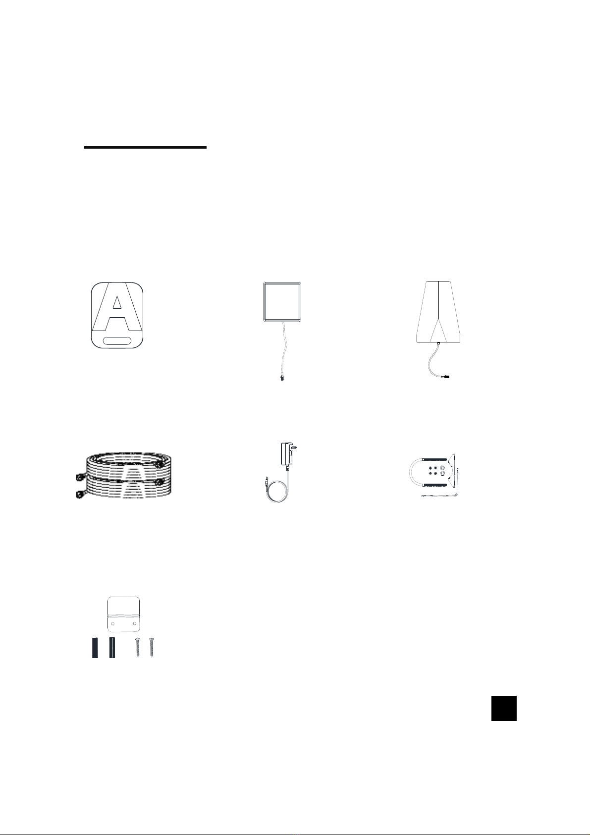
Package
Contents
1
Booster
Loft 3L
Inside
Antenna Outside
Antenna
Power
Supply
Roof/Pole
Mount
Bracket
Wall Mount
Bracket
2*30 ft of
3D-FB
Cables
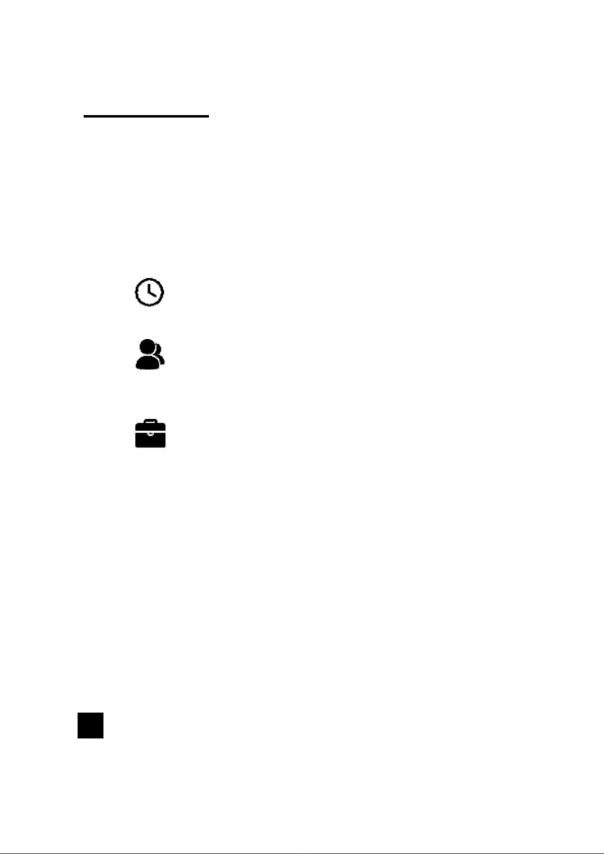
Preparation
You Will Need (tools not included)
Make sure the following materials are prepared and ready for your
installation.
NOTE: These instructions will walk you through a “soft” install process to
find the optimal locations for the inside and outside antennas, then
through the process of the permanent installation.
1 to 2 hours
2 people (a person to help with antenna calibration)
Ladder
Drill (if routing cable through wall)
1”-3”diameter existing pole for mounting
Outdoor Antenna (Pole Mount can be purchased
separately if needed)
Recommended: Power Strip with surge protection
2

Step 1: Inside Antenna
Placement
Choose right position for the indoor antenna
• 1 feet away from any other metallic objects
• 3 feet away from any windows
Place the Inside Antenna where you need the greatest signal boost and
place Booster in your desired location.
NOTE: Do not connect booster to power until the system is fully installed.
3

(STEP1cont.)
Booster Placement
Mount the booster
• Choose a ventilated and dry place
• Keep away from heat
• Don't cover booster
Booster will about 30 degrees Fahrenheit higher than the ambient
temperature, which is a normal phenomenon.
4

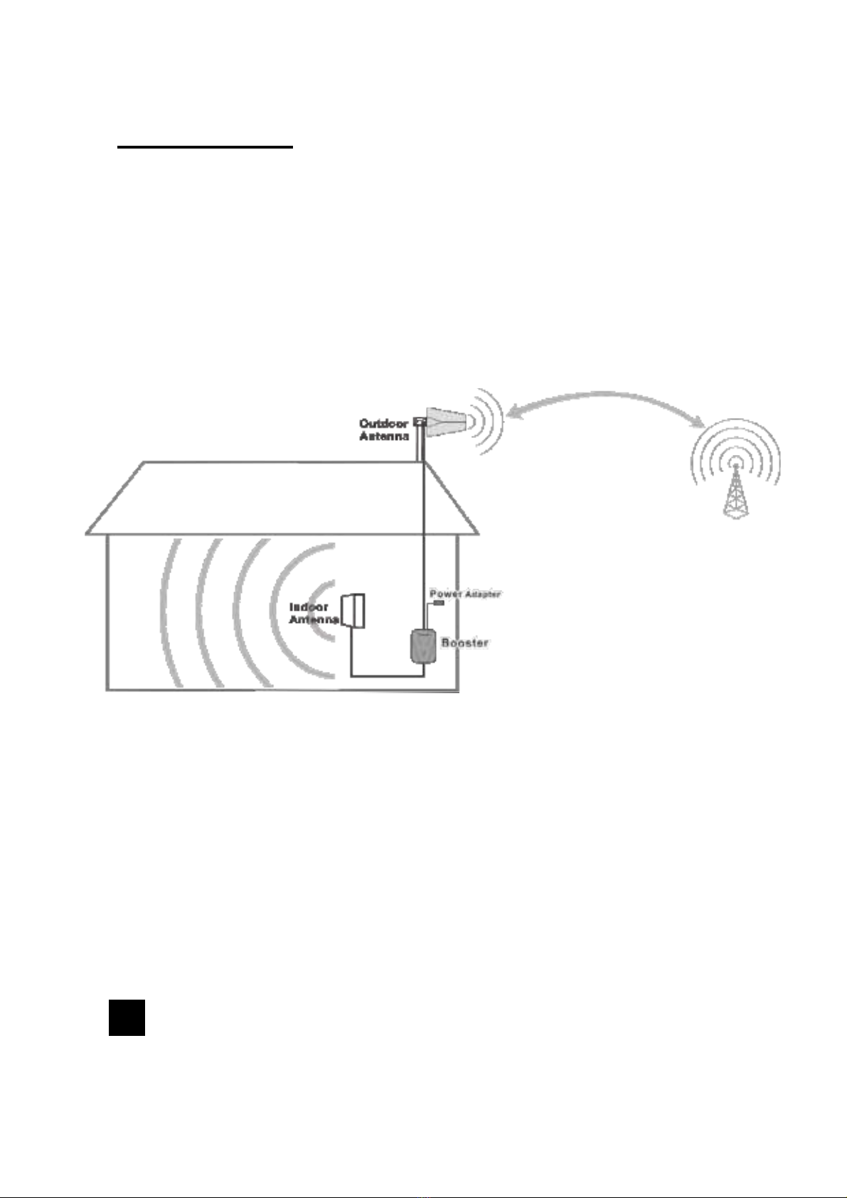
Step 2: Mount & Point
Outside Antenna Toward
Nearest Cell Tower
Pole mounting and wall mounting options are included. The pole
mounting option is preferred because it will be easier to adjust to the
direction of the cell tower.
Attach the Mount to the Outside Antenna and use the Bracket Clamps
to attach the Antenna to a pole or exhaust pipe.
Make sure that the outside unit is mounted at least 3 feet away from any
windows.
Outdoor antenna must be installed over the roof line.
NOTE: Mounting on existing roof exhaust pipe would be a
good time-saver option. Watch out for power lines. 5
①②
③
Point the Outside Antenna toward the nearest cell phone tower. To find
the nearest tower, use an app such as 'Open Signal'. This is the most
critical step of the installation process because it will determine the
overall performance of the booster system.
6

NOTE:
The Outside Antenna must be at least 40 feet (12 meters) Straight line distance or
30 feet (9 meters) horizontal
20 feet (6 meters) vertical from the Inside Antenna for best performance.
Keep enough distance between outside and inside
antenna
The greater the separation between the Inside and Outside Antennas,
the better performance you will get from the booster.
7

Select the optimal mounting location for the outside
antenna
8
After identifying the area of strongest signal, choose the surface where
you will mount your outside antenna.
1. The location should allow for sufficient separation between the outside
antenna and inside antenna.
2. In order to better receive external signals, the outside antenna is best
installed in a higher position on the house, but please pay attention to
lightning protection.
Table of contents
Other SUNFORD ELECTRONICS Extender manuals


