SUNFORD ELECTRONICS APlusBoost Home MultiRoom User manual

www.aplusboost.com
A SUNFORD ELECTRONICS BRAND
NEED HELP ?
Home MultiRoom
Cell Phone Signal Booster
Installation Guide
APlusBoost

CATALOG
Package Contents
Inside Antenna Placement
STEP 1:
Power Up The Booster & Optimize The System
Troubleshooting
Safety Guidelines
Specifications
Warranty
Mount & Point Outside Antenna Toward Nearest
Cell Tower
STEP 2:
Preparation
Route & Connect Outside Antenna To Booster
STEP 3 :
Route & Connect Inside Antenna To Booster
STEP 3 :
STEP 4:
Measuring Booster Performance
Light Patterns
1
2
10
12
13
15
16
17
5
7
8
9
3

Package
Contents
1
Booster Indoor Antenna Outdoor Antenna
60 ft of 3D-FB Cable Power Supply
Mounting Parts of Outdoor Antenna

Preparation
You Will Need (tools not included)
Make sure the following materials are prepared and ready for your
installation.
NOTE: These instructions will walk you through a “soft” install process to
find the optimal locations for the inside and outside antennas, then
through the process of the permanent installation.
2
1 to 2 hours
1 Person (2 people to make antenna calibration easier)
Ladder
Drill (if routing cable through wall)
1”-3”diameter existing pole for mounting
Outdoor Antenna (Pole Mount can be purchased
separately if needed)
Recommended: Power Strip with surge protection

Step 1: Inside Antenna
Placement
3
Choose right position for the indoor antenna
•1 feet away from any other metallic objects
•3 feet away from any windows
Place the Inside Antenna where you need the greatest signal boost and
place Booster in your desired location.
NOTE: Do not connect booster to power until the system is fully installed.

4
(STEP 1-A & B cont.)
Booster Placement
Mount the booster
•Choose a ventilated and dry place
•Keep away from heat
•Don't cover booster
Booster will about 30 degrees Fahrenheit higher than the ambient
temperature, which is a normal phenomenon.

Step 2: Mount & Point
Outside Antenna Toward
Nearest Cell Tower
5
Pole mounting and wall mounting options are included. The pole
mounting option is preferred because it will be easier to adjust to the
direction of the cell tower.
Attach the Mount to the Outside Antenna and use the Bracket Clamps
to attach the Antenna to a pole or exhaust pipe.
Make sure that the outside unit is mounted at least 3 feet away from any
windows.
Outdoor antenna must be installed over the roof line.
NOTE: Mounting on existing roof exhaust pipe would be a
good time-saver option. Watch out for power lines.

6
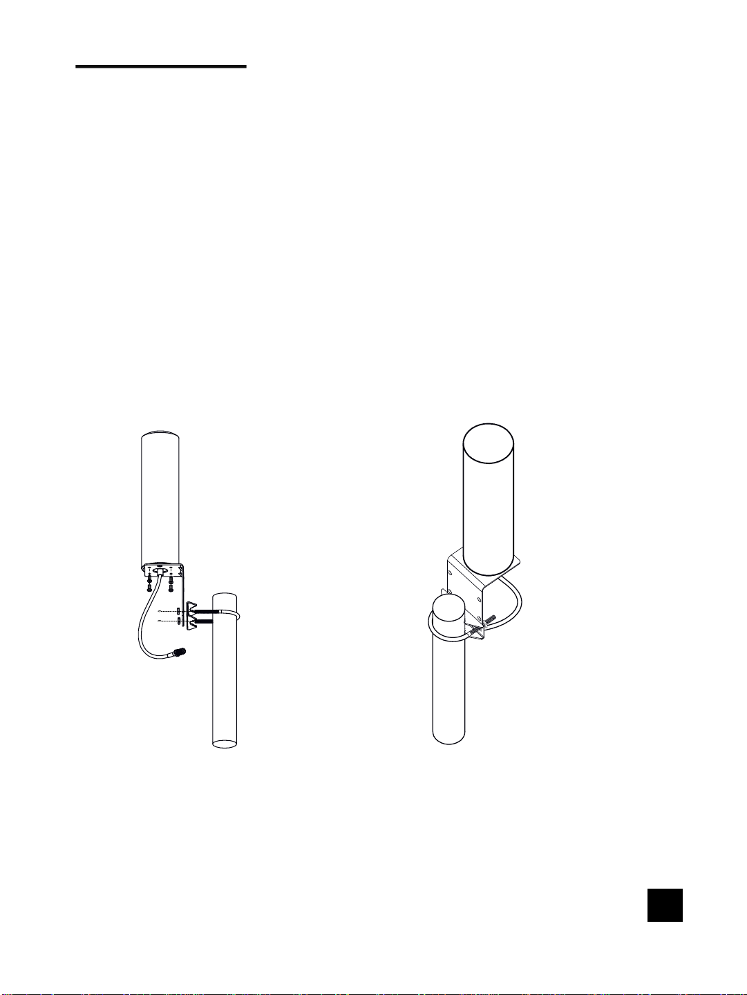
Point the Outside Antenna toward the nearest cell phone tower. To find
the nearest tower, use an app such as 'Open Signal'. This is the most
critical step of the installation process because it will determine the
overall performance of the booster system.
The greater the separation between the Inside and Outside
Antennas, the better performance you will get from the booster.
NOTE: The Outside Antenna must be at least 40 feet (12 meters)
Straight line distance
30 feet (9 meters) horizontal or
20 feet (6 meters) vertical from the Inside Antenna for best
performance. Make sure the InsideAntenna and Outside
Antennas are setup so they are facing away from each other.

7
Step 3: Route & Connect
Outside Antenna To Booster
Connect the white 3D-FB Cable to Outside Antenna and route cable into
the home, secure the cable near the antenna. All connections should be
finger tightened only.
Route cable to the Booster and connect to the port labeled 'OUTSIDE'.

8
Step 3: Route & Connect
Inside Antenna To Booster
Connect the Inside Antenna to the 'INSIDE' port on the booster.

9
Step 4: Power Up The
Booster & Optimize The
System
Plug in the Power Supply and connect it to the nearest power outlet.
NOTE: We strongly recommend using a power strip with surge protection.

Measuring Booster
Performance
10
How To Get Signal Strength As A Number
iPhone®
Android™
iOS 11 and later no longer displays the decibel (dBm)
reading in 'Field Test Mode'. Tip: Using the dot signal
strength indicator on your cell phone can assist you
in finding the strongest signal direction as well as
placing calls in different locations.
iPhone: dial *3001#12345#* then press call
Settings > About Phone > Status or Network > Signal
Strength or Network Type and Strength (exact
options/wording depends on phone model).
Android: download third part APP-LTE Discovery
iPhone is a registered trademark of Apple Inc. Android is a
trademark of Google Inc.

11
DID YOU KNOW a signal increase of just 3dB is 2 times the
power and signal amplification!
(MEASURING BOOSTER PERFORMANCE cont.)
Signal Strength without Booster
Note here:
Signal Strength with Booster
Note here:
Compare Results
Having an accurate measurement of signal strength in decibels (dBm) is
crucial when installing your system. Decibels accurately measure the signal
strength you are receiving.

Light Patterns
12
Panel Indicator
CorrectFunctioning:
•The band indicator lights on the front panel
indicate the status of each band of the booster.
Every time the power is turned on, all the
indicators will turn green for about 1 second.
This means that the booster has passed the self-
test and is in good condition. When there is no
problem with the system, all the indicators
remain solid green during operation.
Band Indicator Lights Blinking Red:
•Band has reduced gain. Which lights blinking indicate that the corresponding
booster bands have reduced power due to a feedback loop condition called
oscillation. This is a built in safety feature to prevent harmful interference
with a nearby cell tower. If you are already experiencing the desired signal
boost, then no further adjustments are necessary. If you are not
experiencing the desired boost in coverage then refer to the Troubleshooting
section.
Band Indicator Lights Solid Red:
•Band has shutoff. This is due to a feedback loop condition called oscillation.
This is a built in safety feature that causes a band to shut off to prevent
harmful interference with a nearby cell tower. Refer to Troubleshooting
section.

13
Troubleshooting
IF YOU ARE HAPPY WITH THE COVERAGE, THESE LIGHT ISSUES DON'T HAVE TO
BE RESOLVED. YOUR CARRIER'S BAND HAS NOT BEEN AFFECTED.
www.aplusboost.com
NEED HELP ?
FIXING ANY BAND INDICATOR LIGHTS BLINKING ISSUES
Band Indicator Lights Blinking Red
1. Band Indicator Lights Blink 1 To 15 Times (1 cycle)
That means the gain lowered 1~15 dB. If your coverage is good and reception
is good, you can ignore the blink.
2. Band Indicator Lights Blink All The Time
That means the gain lowered 15~25 dB. Check and install the whole system
again.
FIXING ANY BAND INDICATOR LIGHTS SOLID ORANGE
ISSUES
Band Indicator Lights Solid Orange
That means shut down. Check and install the whole system again.
ALL INDICATOR LIGHTS ARE NOT ON
Please verify your power supply has power; contact with us by email or call for
replacement.

Troubleshooting
How does oscillation happened:
1. Indoor antenna receive leak signal from the outdoor antenna;
2. Booster amplify the signal and then transmit it to the outdoor antenna;
3. Outdoor antenna broadcast the signal in the air, some of the signal
back to indoor antenna and become leak signal;
4. If the gain of the booster higher than the loss of the leak signal, the
leak signal will become bigger and bigger, finally oscillation happened.
How to confirm that oscillation has occurred:
1. Panel light flash or solid red/orange after power on;
2. Screw off the indoor antenna from the booster;
3. Restart the power supply;
4. All indicator lights flash once time after power on show self-test
finished;
How to solve the problem of oscillation:
Keep enough distance between indoor and outdoor
antenna
Minimum Required Separation Distance Between Indoor and Outdoor
Antennas:
Straight line distance over 40 feet(12 meters) or
30 feet (9 meters) horizontal distance
20 feet (6meters) vertical distance (as far as possible).
14

To uphold network protection standards and ensure compliance, all active cellular
devices must maintain a separation distance of at least six feet between the inside unit
antenna and outside unit antenna and at least four feet of separation distance from the
inside unit.
Use of a non-APlusBoost product or accessory may result in damage to the equipment or
components of the equipment.
The inside unit is designed for use in an indoor, temperature-controlled environment
(less than 100 degrees Fahrenheit). It is not intended for use in attics or similar
locations where temperatures may be in excess of that range.
Sprint: http://www.sprint.com/legal/fcc_boosters.html
T-Mobile/MetroPCS: https://support.t-mobile.com/docs/DOC-9827
Verizon Wireless: http://www.verizonwireless.com/wcms/consumer/register-signal-booster.html
AT&T: https://securec45.securewebsession.com/attsignalbooster.com/
U.S. Cellular: http://www.uscellular.com/uscellular/support/fcc-booster-registration.jsp
FOR MORE INFORMATION ON REGISTERING YOUR SIGNAL BOOSTER WITH
YOUR WIRELESS PROVIDER, PLEASE SEE BELOW:
RF Safety Warning: Any antenna used with this device must be located at least 8
inches from all persons.
Safety Guidelines
15
This device may be operated ONLY in a fixed location for in-building use.

Specifications
www.aplusboost.com
NEED HELP ?
This device complies with Part 15 of FCC rules. Operation is subject to two conditions:
(1) This device may not cause harmful interference, and (2) this device must accept any
interference received, including interference that may cause undesired operation.
Changes or modifications not expressly approved by APlusBoost could void the authority
to operate this equipment.
CPC-2-1-05 — Zone Enhancers - Spectrum management and telecommunications
http://www.ic.gc.ca/eic/site/smt-gst.nsf/eng/sf08942.html
Warning:Unauthorized antennas/cables and/or coupling devices are prohibited by FCC
rules. Please contact FCC for details: 1-888-CALL-FCC
16
Model Number SF-002
FCC 2A34B-SFZN002
Connectors F-Female on the inside Antenna / F-Female on the Outside Antenna
Noise figure 5 dB nominal
Antenna lmpedance 75 Ohms / 75 Ohms
Weight 0.35Kg
Frequency 698-716MHz,776-787MHz,824-849MHz,1850-1915MHz,1710-1755MHz
728-746MHz,746-757MHz,869-894MHz,1930-1995MHz,2110-2155MHz
Power output for single cell phone
(Uplink)dBm
700A-MHz 700V-MHz 800MHz 1900MHz 1700MHz
Band12 Band13 Band5 Band2 Band4
62 62 62 65 65
Power output for single cell phone
(Downlink)dBm
700A-MHz 700V-MHz 800MHz 1900MHz 2100MHz
Band12 Band13 Band5 Band2 Band4
64 64 65 68 68
EIRP 1W Max
Operating temperature 5℉to 140℉(-15℃~60 ℃)
lsolation >110 dB
Power Requirements AC / DC 12V,1.5A, w/1.35X3.5mm Jack

DISCLAIMER: The information provided by APlusBoost is believed to be complete and
accurate, to the best of our knowledge. However, no responsibility is assumed by
APlusBoost for any business or personal losses arising from the use of the information
herein contained, or for any infringements of patents or other rights of third parties that
may result from its use.
2 Y2 YEAR WARRANTYEAR WARRANTY
3 YEAR WARRANTY
The Booster is covered under a three-year product warranty for failures or defects
that result from craftsmanship and/or materials. Dated proof of purchase should be
retained for use in warranty cases. Contact the retailer/reseller directly with any
warranty issues, or alternatively contact the manufacturer in cases where the
reseller is no longer available to handle warranty claims. In cases where the reseller
is unavailable, the product may be returned to the manufacturer at the consumer's
expense, with a dated proof of purchase and a return authorization letter which can
be attained by contacting APlusBoost.
This warranty does not apply to any signal booster components determined by
APlusBoost to have been subjected to misuse, abuse, neglect, tampering, or
mishandling that result in damages to the physical or electronic properties of the
product. Refurbished products that have been recertified to conform to product
specifications may be used for product replacements.
17
Booster transmitting in 1710-1755 MHz should be install/operate in one of two ways:
(i) the antenna for the device must be installed to comply with the 10 meter above
ground maximum antenna height limitation OR
(ii) the antenna for the device has a 10 meter above ground maximum antenna height
limitation when the device is used with a handset that covers the 1710-1755 MHz band and
that owners could be subject to potential FCC enforcement action for noncompliance.

Table of contents
Other SUNFORD ELECTRONICS Extender manuals
Popular Extender manuals by other brands

Linksys
Linksys DMA2200 - Media Center Extender user guide

Marmitek
Marmitek POWERMID XL user manual

Powerful Signal
Powerful Signal SolidRF Signal Plus installation guide

ADLINK Technology
ADLINK Technology PCIS-8580-4S user manual

Eaton
Eaton TRIPP LITE Series installation instructions

ATEN
ATEN KX Series user manual