SunFounder Sensor Kit V1.0 User manual

Preface
About SunFounder
SunFounder is a technology company focused on Raspberry Pi and Arduino open source
community development. Committed to the promotion of open source culture, we strive to
bring the fun of electronics making to people all around the world and enable everyone to
be a maker. Our products include learning kits, development boards, robots, sensor modules
and development tools. In addition to high quality products, SunFounder also offers video
tutorials to help you build your own project. If you have interest in open source or making
something cool, welcome to join us! Visit www.sunfounder.com for more!
About Sensor Kit V1.0
This kit is suitable for SunFounder Uno, SunFounder Mega 2560, SunFounder Duemilanove and
SunFounder Nano. All the code in this user manual is compatible with these boards.
Our SunFounder board is fully compatible with Arduino board.
You can go to our official website www.sunfounder.com to download related code by
clicking LEARN -> Get Tutorials. If you have any questions, please send an email to
support@sunfounder.com. Also welcome to leave a message and share your projects on our
FORUM.
Note: This kit is different from other kits. All the components in this kit are provided in the form
of modules which integrate some necessary components, such as comparator, resistor, and
capacitor and so on. Therefore it is convenient for circuit connection.
Reprint 2.0
SunFounder

Contents
Components List .................................................................................................................................. 1
Notice .................................................................................................................................................... 8
Lesson 1 Hall Sensor ........................................................................................................................... 10
Lesson 2 RGB LED ............................................................................................................................... 15
Lesson 3 Dual-color Common-Cathode LED ................................................................................. 18
Lesson 4 Shock Switch ....................................................................................................................... 20
Lesson 5 Knock Sensor ...................................................................................................................... 22
Lesson 6 Infrared Transmitter ............................................................................................................ 24
Lesson 7 Laser Transmitter ................................................................................................................. 26
Lesson 8 Reed Switch ........................................................................................................................ 28
Lesson 9 Infrared-Receiver ............................................................................................................... 31
Lesson 10 Analog Temperature Sensor ........................................................................................... 33
Lesson 11 Digital Temperature Sensor ............................................................................................ 35
Lesson 12 Buzzer ................................................................................................................................. 37
Lesson 13 Button Switch .................................................................................................................... 40
Lesson 14 Photo-interrupter .............................................................................................................. 42
Lesson 15 Tilt-Switch ........................................................................................................................... 44
Lesson 16 Mercury Switch ................................................................................................................. 46
Lesson 17 Magic Cup ........................................................................................................................ 48
Lesson 18 DS18B20 Temperature Sensor ......................................................................................... 50
Lesson 19 Rotary Encoder ................................................................................................................ 52
Lesson 20 7-Color Auto-flash LED ..................................................................................................... 55
Lesson 21 Photoresistor Sensor ......................................................................................................... 56
Lesson 22 Humiture Sensor ................................................................................................................ 58
Lesson 23 Obstacle Avoidance Sensor .......................................................................................... 60
Lesson 24 Tracking Sensor ................................................................................................................. 62
Lesson 25 Microphone Sensor .......................................................................................................... 64
Lesson 26 Metal Touch Sensor ......................................................................................................... 67
SunFounder

Lesson 27 Flame Sensor ..................................................................................................................... 69
Lesson 28 Relay Module ................................................................................................................... 71
Lesson 29 Joystick PS2 ....................................................................................................................... 73
Lesson 30 MQ-2 Gas Sensor.............................................................................................................. 75
Lesson 31 Password Lock .................................................................................................................. 77
Lesson 32 Lie Detector ...................................................................................................................... 79
Lesson 33 Fire Alarm .......................................................................................................................... 81
Lesson 34 Thermostatic Water Tank System ................................................................................... 83
Lesson 35 Intelligent Environment Monitoring ................................................................................ 85
SunFounder
1
Components List
No. Name Qty. Component
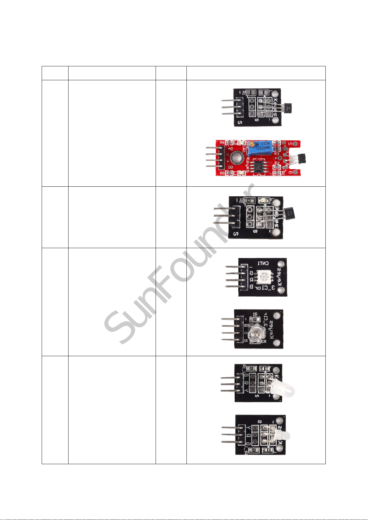
1 Analog Hall Sensor 2
2 Switch Hall Sensor 1
3 RGB LED 2
4 Dual-color
Common-Cathode LED
2
SunFounder

2
5 Shock Switch 1
6 Knock Sensor 1
7 Infrared Transmitter 1
8 Laser Transmitter 1
9 Reed Switch 1
10 Mini Reed 1
11 Infrared Receiver 1
SunFounder

3
12 Analog Temperature
Sensor
1
13 Digital Temperature
Sensor
1
14 Active Buzzer 1
15 Passive Buzzer 1
16 Button Switch 1
17 Photo-interrupter 1
18 Tilt Switch 1
SunFounder

4
19 Mercury Switch 1
20 Magic Cup 2
21 DS18B20 Temperature
Sensor
1
22 Rotary Encoder 1
23 7-color Auto-flash LED 1
24 Photoresistor Sensor 1
SunFounder
5
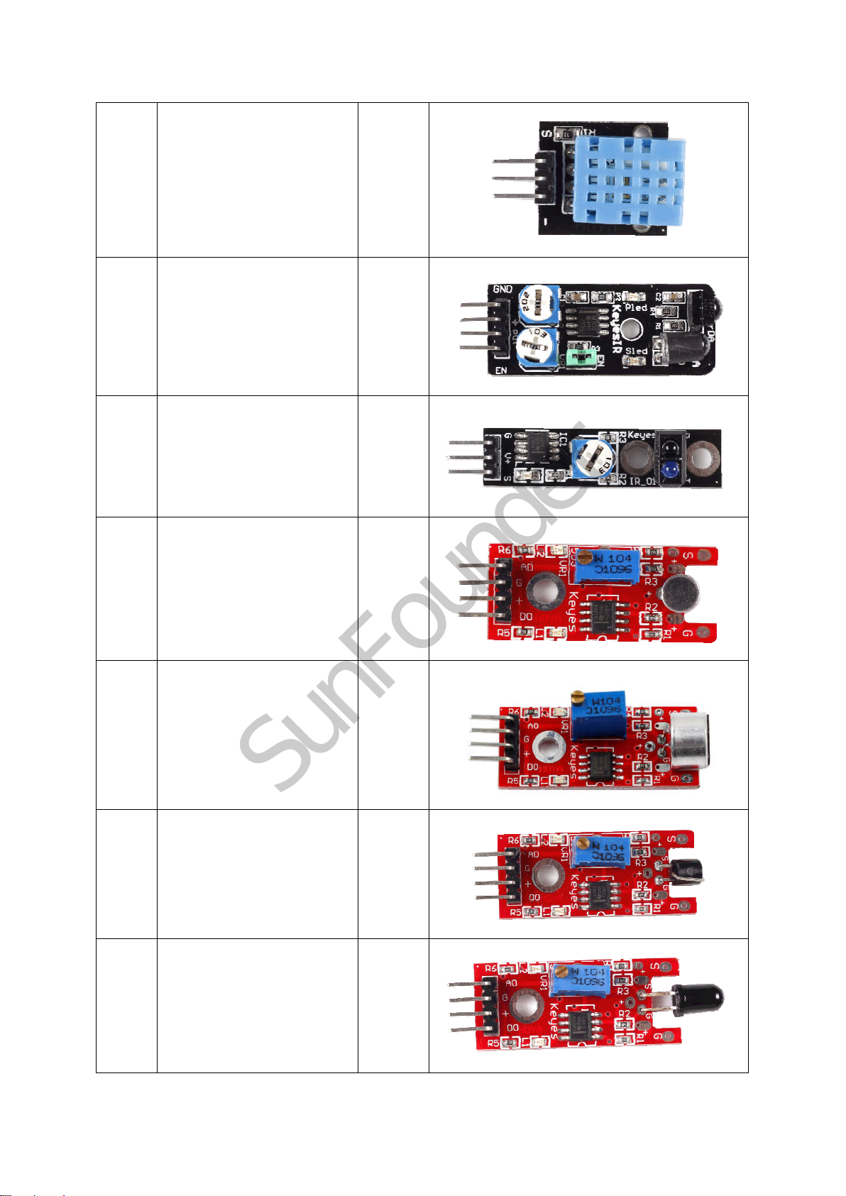
25 Humiture Sensor 1
26 Obstacle Avoidance
Sensor
1
27 Tracking Sensor 1
28 Microphone Sensor 1
29 High-sensitive Voice
Sensor
1
30 Metal Touch Sensor 1
31 Flame Sensor 1
SunFounder
6
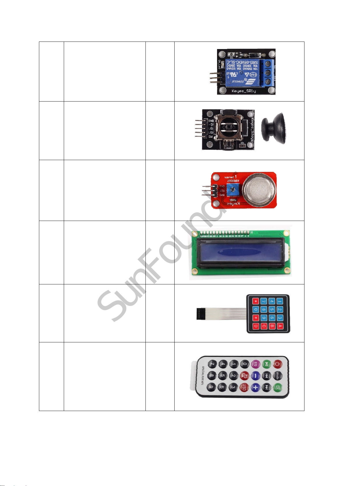
32 Relay Module 1
33 Joystick PS2 1
34 MQ-2 Gas Sensor 1
35 LCD1602 1
36 4x4 Keypad 1
37 Remote Control 1
SunFounder
7
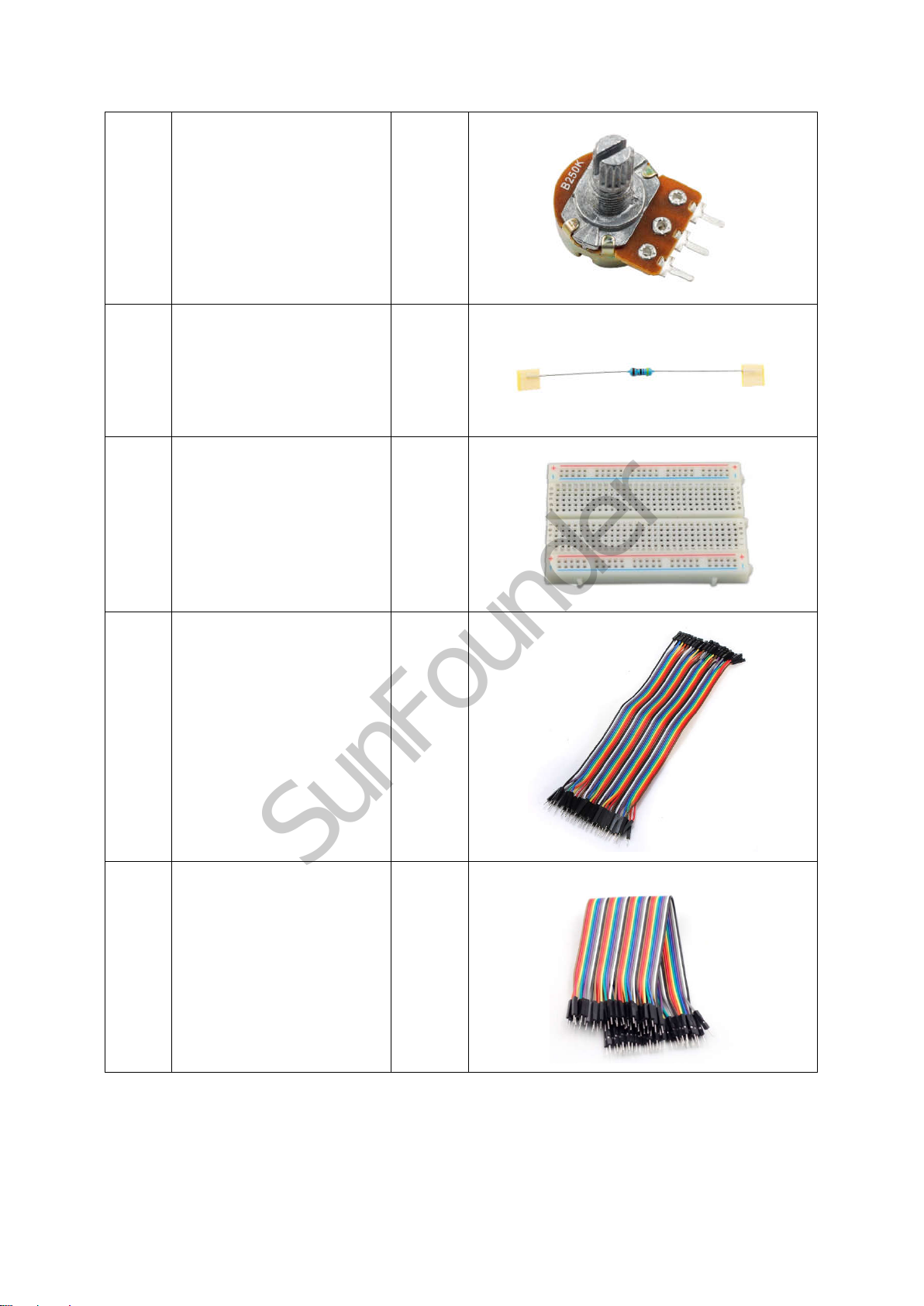
38 250k Ohm
Potentiometer
1
39 470k Ohm Resistor 1
40 Breadboard 1
41 Jumper Wire
(M to F)
40
42 Jumper Wire
(M to M)
20
SunFounder
Table of contents
Other SunFounder Accessories manuals


