Sungrow EMU200A User manual

EEMMUU220000AAEEnneerrggyy MMaannaaggeemmeenntt
UUnniittUUsseerr MMaannuuaallEEMMUU220000AA--UUEENN--
VVeerr1111--220022111100
EMU200A-UEN-Ver11-202110
EMU200A
EEnneerrggyy MMaannaaggeemmeenntt UUnniitt
UUsseerr MMaannuuaall


I
CCoonntteennttss
1 About This Manual ....................................................................................... 1
1.1 Intended Use................................................................................................ 1
1.2 Target Group................................................................................................ 1
1.3 How to Use This Manual............................................................................... 1
1.4 Additional Information .................................................................................. 1
1.5 Symbol Explanation...................................................................................... 2
2 Safety Instructions ...................................................................................... 3
3 Product Description .................................................................................... 5
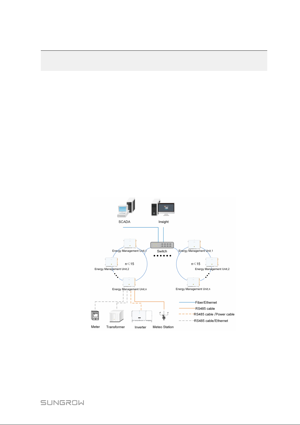
3.1 Networking Scenarios .................................................................................. 5
3.2 Main Features.............................................................................................. 6
3.3 Dimensions.................................................................................................. 7
4 Mechanical Mounting ................................................................................ 8
4.1 Inspection before Installation ........................................................................ 8
4.2 Installation Tools........................................................................................... 9
4.3 Location Requirements .............................................................................. 10
4.4 Installation Method..................................................................................... 10
4.4.1 Wall Mounting .................................................................................. 10
4.4.2 Bracket Mounting ............................................................................. 12
4.4.3 Ground Mounting ............................................................................. 12
4.4.4 Pole Mounting .................................................................................. 13
4.5 Installing IO Modules (Optional) .................................................................. 14
5 Electrical Connection ............................................................................... 17
5.1 Waterproof Terminal Description ................................................................ 17
5.2 Internal Structure........................................................................................ 17
5.3 Connection Overview ................................................................................. 19
5.4 Preparation Before Connection................................................................... 20
5.5 Connection Steps....................................................................................... 21
5.5.1 Grounding ........................................................................................ 21
5.5.2 RS485 Communication Terminal Connection .................................... 24
5.5.3 Optical Fibre (Optional) ..................................................................... 25
5.5.4 Power Supply Connection................................................................. 25

II
5.5.5 PLC Port Connection ........................................................................ 27
5.5.6 DI/DO Port Connection ..................................................................... 31
5.6 Post-wiring processing............................................................................... 31
6 Commissioning ........................................................................................... 32
6.1 Inspection before Commissioning............................................................... 32
6.2 Commissioning Steps................................................................................. 32
7 Troubleshooting ......................................................................................... 34
8 Appendix A: Technical Parameters ...................................................... 35
9 Appendix B: General Information ......................................................... 36
9.1 Quality Assurance ...................................................................................... 36
9.2 Contact Information ................................................................................... 36

1
1 About This Manual
1.1 Intended Use
This manual is intended to provide the reader with detailed information and description
of the installation and operation about the following products:
•EMU200A
It is referred to as "device" for short unless otherwise specified。
1.2 Target Group
This manual is intended for technically qualified persons who need to install and operate
the device.
1.3 How to Use This Manual
Read this manual carefully before performing operation on the device. Keep the manual
in a convenient place for future reference.
All rights reserved including the pictures, symbols, and markings used in this manual.
Any disclosure, even partially, of the contents of this manual is strictly prohibited without
prior written authorization of SUNGROW.
The content of the manual will be periodically updated or revised as per the product de-
velopment. It is probably that there are changes in manuals for the subsequent module
edition. If there any mismatch between the product and its manual, the actual product
shall govern.
1.4 Additional Information
For more details about the equipment inside EMU200A, please scan the following QR
codes.
DDeevviiccee RReellaatteedd ddooccuummeennttss
Logger4000

2
1.5 Symbol Explanation
This manual contains important safety and operational instructions that must be accu-
rately understood and respected during the installation and maintenance of the device.
To ensure the optimum use of this manual, note the following explanations of the sym-
bols used.
DANGER indicates a hazard with a high level of risk which, if not avoided, will re-
sult in death or serious injury.
WARNING indicates a hazard with a medium level of risk which, if not avoided,
could result in death or serious injury
CAUTION indicates a hazard with a low level of risk which, if not avoided, could
result in minor or moderate injury.
NOTICE indicates a situation which, if not avoided, could result in equipment or
property damage.
indicates additional information, emphasized contents or tips to help you solve
problems or save time.
1 About This Manual User Manual

3
2Safety Instructions
This chapter mainly introduces safety instructions that need to be respected during the
operation of Energy Management Unit EMU200A.
The EMU200A has been designed and tested strictly according to international safety
regulations. As electrical and electronic equipment, the EMU200A must be installed,
commissioned, operated, and maintained in strict accordance with related safety
instructions. Incorrect operation or misuse of the device may cause:
•damage to personnel safety of the operators or the third party
•damage to the EMU200A or other properties belong to the operators or the third
party
Therefore, the following safety instructions must be read and always kept in mind prior
to any work. All detailed work-related safety warnings and notes will be specified at the
critical points in corresponding chapter.
All operations and electrical work must only be performed by qualified
personnel.
BBeeffoorree IInnssttaallllaattiioonn
After receiving the device, please check if there is damage caused during
transport. Contact SUNGROW or the forwarding company once any problem is
found.
The related operators must be familiar with the safety instructions in this manual
and other safety regulations about the installation, operation and maintenance
of the EMU200A.
Move, transport, install, operate, and maintain the EMU200A correctly and
appropriately.
DDuurriinngg IInnssttaallllaattiioonn
The EMU200A can only be used as described in this manual. Altering the
product without authorization or using spare parts not sold or recommended by
SUNGROW may lead to fire, electric shock or other damages.

4
Disconnect all electrical connections and the upstream input switch and make
sure the EMU200A is voltage-free during installation.
MMaaiinntteennaannccee aanndd RReeppllaacceemmeenntt
Do not ingest battery.Chemical burn hazard!
This product contains a coin / button cell battery. If the coin / button cell battery
is swallowed, it can cause a severe internal burns in just 2 hours and can lead to
death.
The maintenance of the EMU200A can only be performed by qualified
personnel from SUNGROW or other qualified personnel.
User can never maintain or replace the modules and other parts. Serious
personal injury or property loss may follow if otherwise.
Never replace the internal components of the EMU200A without authorization.
SUNGROW shall not be held liable for any possible damage caused by
ignorance of this warning.
2 Safety Instructions User Manual

5
3Product Description
3.1 Networking Scenarios
EMU200A is equipped with a Logger4000 inside, whith which EMU200A can be applied
to various networking scenarios. It can access the inverter, box-type transformer, meteo
station and meter in the PV power generation system through RS485 bus, and can also
access the string inverter with PLC function produced by SUNGROW through PLC bus.
•EMU200A can transmit the collected device data to the background plant controller,
such as Insight and SCADA, through the core switch.
•EMU200A can also transmit the collected device data directly to iSolarCloud through
the 4G router.
CCoonnnneecctteedd ttoo bbaacckkggrroouunndd ppllaanntt ccoonnttrroolllleerr tthhrroouugghh aa ccoorree sswwiittcchh
EMU200A can be connected to Insight or SCADA through a core switch, as shown
below.
ffiigguurree 33--11 Ring networking
When the ring networking is used, a maximum of 15 EMU200A can be connected to a
ring network.

6
ffiigguurree 33--22 Star networking
CCoonnnneecctteedd ttoo iiSSoollaarrCClloouudd tthhrroouugghh aa rroouutteerr
EMU200A can be directly connected to the iSolarCloud through a router, as shown
below.
3.2 Main Features
FFlleexxiibbllee nneettwwoorrkkiinngg
•Support of RS485, Ethernet and MPLC communication.
•Support of tracker, meteo station, sensors and other equipment.
CCoonnvveenniieenntt OO&&MM
•Inverter batch parameter settings and firmware updates.
3 Product Description User Manual

8
4Mechanical Mounting
Respect all local standards and requirements during mechanical installation.
4.1 Inspection before Installation
Check the scope of delivery for completeness according to the packing list. The follow-
ing items should be included:
IItteemm DDeessccrriippttiioonn SSuumm
A EMU200A 1
B
Documents, including certificate, war-
ranty card, delivery inspection report,
quick installation instruction, etc.
1
CKeys 1
DM10x45 bolt assembly 4
E M6x14 bolt 1
FOT terminal(RNBL5-4) 2
G* IO module ≤4
* is optional
The device is carefully tested and inspected before delivery, but damage may
be caused during shipping. Therefore, inspect the device before installation. If
there any damage, contact the forwarding company or SUNGROW.

9
4.2 Installation Tools
Installation tools include but are not limited to the following recommended ones. If nec-
essary, use other auxiliary tools on site.
table 4-1 Tool specification
Goggles Earplugs Dust mask Dust mask
Insulated shoes Utility knife Marker Wrist strap
Level Hammer drill
(φ12)
Phillips screwdriver
(M4, M6)
Slotted screwdriver
(M2)
Rubber mallet Wrench (18 mm,
21 mm)
Pliers Wire cutter
Wire stripper Tube crimp Heat gun Multimeter (≥
1500 Vdc)
User Manual 4 Mechanical Mounting

10
4.3 Location Requirements
•With the ingress of protection IP65, EMU200A can be installed outdoors.
•Ambient temperature: -30℃ to +60℃,and ambient humidity: ≤ 95%, without con-
densation. Excessive moisture can damage internal components.
•Take anti-moisture and anti-corrosion measures.
4.4 Installation Method
Beware of the weight of the device throughout the installation process!
Tilting or falling of the device due to inappropriate processing can cause person-
al injury!
The installation dimensions of mounting ears on the back of the device are shown in the
following figure (unit:mm).
Wall mounting and bracket mounting are both available. Choose the corresponding in-
stallation method according to actual needs.
4.4.1 Wall Mounting
step 1 Mark the hole locations on the installation wall according to the foregoing installation
dimensions.
step 2 Drill holes on the marked locations.
4 Mechanical Mounting User Manual

11
step 3 Place the M10X45 expansion sleeve(not included in the scope of delivery) into the hole,
and tap it with a rubber hammer. Make it completely embedded in the wall.
Select expansion bolts with proper length according to the depth of drilling.
step 4 Fasten the device on the wall in the order of nut, lock washer, flat washer, mounting ear.
-- -- EEnndd
User Manual 4 Mechanical Mounting

12
4.4.2 Bracket Mounting
step 1 Mark the hole locations on the mounting brackets according to the installation dimen-
sions of mouting ears and drill holes on the marked locations according to bolt
specifications.
step 2 Fasten the device on the brackets in the order of M10x45 bolt, mounting ear, mounting
bracket.
step 3 Check to ensure the device is firmly in place.
-- -- EEnndd
4.4.3 Ground Mounting
For the ground mounting, the device is fixed to the foundation via the installation holes in
the bottom of the device (shown in Figure A below).
step 1 Construct the foundation according to the exterior dimensions of the device.
step 2 Pre-embed the foundation bolts in the four corners of the foundation, and the bolts used
are M10.
4 Mechanical Mounting User Manual

13
The foundation bolts are not in the scope of delivery
step 3 Secure the installation holes in bottom of the device to the foundation with a fastening
torque of 37±3N.m.
-- -- EEnndd
4.4.4 Pole Mounting
EMU200A supports pole mounting. If necessary, specify your requirements when plac-
ing an order. SUNGROW will design according to actual installation conditions.
Accessories supplied with EMU200A include matching screw combinations, nuts,
brackets, clamps, and the like.
step 1 Fasten the mounting ears of EMU200A onto the brackets by using the matching screw
combinations, as shown in the figure below.
step 2 Fix the brackets and the clamps by using the nuts.
User Manual 4 Mechanical Mounting

14
-- -- EEnndd
4.5 Installing IO Modules (Optional)
This operation is required if IO modules are ordered.
step 1 Remove the IO modules assembly from the IO module deliverables.
step 2 Set communication address. Find the dip switch on the back, and set the communica-
tion address through the dip switch. The setting range of the communication address is
from 1 to 15.
EExxaammppllee ooff ccoommmmuu--
nniiccaattiioonn aaddddrreessss
sseettttiinngg
BBiinnaarryy aaddddrreessss DDeecciimmaall aaddddrreessss
0001 1
(1×20=1)
0010 2
(1×21+0×20=2)
4 Mechanical Mounting User Manual

15
EExxaammppllee ooff ccoommmmuu--
nniiccaattiioonn aaddddrreessss
sseettttiinngg
BBiinnaarryy aaddddrreessss DDeecciimmaall aaddddrreessss
0011 3
(1×21+1×20=3)
1111 1x23+1x22+1x21+1x20=15
The dip switch addresses on each IO module must be different.
step 3 Insert I/O modules into the reserved area.
step 4 Install the four IO modules as shown in the following figure.
User Manual 4 Mechanical Mounting
Other manuals for EMU200A
2
Table of contents
Other Sungrow Batteries Pack manuals